
In the field of modern manufacturing, gear hobbing remains a critical process for producing high-precision gears used in various industries such as automotive, aerospace, and machinery. We have developed an advanced CNC gear hobbing machine, the Y3132CNC6, which exemplifies our commitment to innovation and quality in gear hobbing technology. This machine is designed to handle high-speed and high-precision gear hobbing operations, making it ideal for mass production of cylindrical spur gears, helical gears, and other complex gear profiles. Our focus on rigorous quality control throughout the design, manufacturing, and assembly processes ensures that this gear hobbing machine delivers exceptional performance, reliability, and accuracy, consistently meeting international standards.
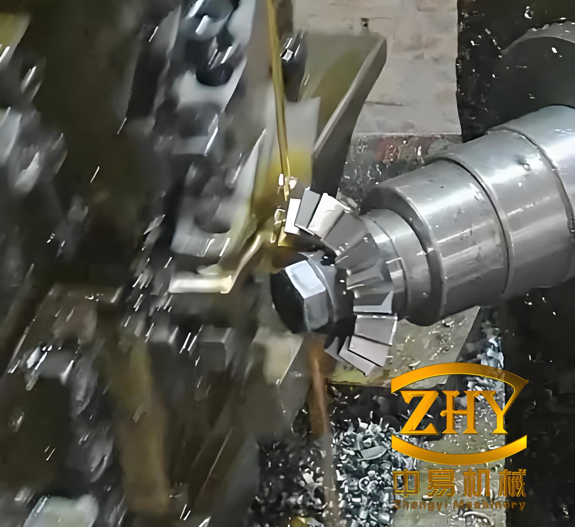
The Y3132CNC6 CNC gear hobbing machine is a six-axis, four-linkage system that enables efficient and precise gear hobbing for workpieces with modules up to 5 mm and diameters reaching 320 mm. With a maximum cutting speed of 120 m/min and the ability to achieve accuracy levels up to GB/T10095.1-2008 Grade 6, this machine is engineered for high-load and high-speed operations. It supports a variety of gear types, including spur gears, helical gears, small taper gears, crown gears, and gears with low tooth counts, as well as splines. The gear hobbing process on this machine involves continuous indexing, which ensures smooth and accurate tooth generation. Key features include a robust bed and column structure with multi-layer ribbed box designs for enhanced rigidity, imported bearing combinations for the tool spindle and workpiece spindle to ensure stability, and an innovative thermal balancing system that minimizes thermal deformation during prolonged gear hobbing operations. Additionally, the machine can be equipped with an automatic loading and unloading system, making it suitable for integration into automated production lines where quick changeovers and short cycle times are essential.
To provide a clear overview of the machine’s capabilities, the following table summarizes the main technical parameters of the Y3132CNC6 CNC gear hobbing machine. These parameters are critical for understanding the scope of gear hobbing tasks it can handle, from small precision components to larger industrial gears.
| Parameter | Value | Description |
|---|---|---|
| Maximum Workpiece Diameter | φ320 mm | Largest diameter of gear that can be processed |
| Maximum Workpiece Module | 8 mm | Largest module size for gear hobbing |
| Slide Travel (Z-axis Movement) | 360 mm | Axial movement range for the sliding table |
| Tool Holder Maximum Rotation Angle | ±45° | Angular adjustment for helical gear hobbing |
| Tool Spindle Speed | 120–700 rpm | Rotational speed range of the hobbing cutter |
| Workpiece Spindle Maximum Speed | 60 rpm | Highest rotational speed of the workpiece |
| Maximum Tool Dimensions (Diameter × Length) | φ170 × 230 mm | Largest allowable hobbing cutter size |
| Maximum Axial Movement of Hob | 200 mm | Axial travel of the hobbing tool for depth control |
The gear hobbing process on this machine relies on precise mathematical relationships to ensure optimal performance. For instance, the cutting speed in gear hobbing can be calculated using the formula: $$v = \pi \cdot d \cdot n$$ where \(v\) is the cutting speed in m/min, \(d\) is the diameter of the hobbing cutter in meters, and \(n\) is the spindle speed in rpm. This equation is fundamental for setting up the gear hobbing machine to achieve desired surface finishes and tool life. Additionally, the feed rate per revolution, which affects the quality of the gear teeth, is given by: $$f = \frac{v_f}{n}$$ where \(f\) is the feed per revolution in mm/rev, and \(v_f\) is the feed velocity in mm/min. By optimizing these parameters, our gear hobbing machine maintains high efficiency and accuracy across various applications.
Quality control is integral to the development of the Y3132CNC6 CNC gear hobbing machine, and we adhere to a comprehensive quality management system based on ISO 9001:2015 standards. This system covers every stage from design and prototyping to production and售后服务, ensuring that each gear hobbing machine meets stringent requirements for precision, durability, and performance. Our processes are documented and traceable, with regular audits and reviews to identify and address potential issues early. In the following sections, we will delve into the specific quality control measures implemented during the design, process planning, part machining, and assembly stages, highlighting how they contribute to the reliability of our gear hobbing technology.
Design Process Quality Control
In the design phase of the Y3132CNC6 CNC gear hobbing machine, we focus on creating a robust and efficient platform for gear hobbing operations. Our approach begins with extensive preliminary research, where we gather data on global trends in gear hobbing technology, user feedback on existing gear hobbing machines, and advancements in machining processes. This helps us identify best practices and avoid common pitfalls in gear hobbing machine design. We follow a structured workflow as per our internal quality management procedures, which emphasizes documentation and compliance with mechanical design standards. For example, we analyze factors such as dynamic loads and thermal effects that are critical in gear hobbing applications, using this data to inform our design decisions and ensure the machine can withstand high-speed operations.
We employ advanced design tools to enhance the quality of the gear hobbing machine. Using 3D CAD software, we develop modular designs that allow for flexible configurations and easy maintenance. The design process starts with layout diagrams, progresses to component-level designs, and culminates in a digital prototype. This virtual model enables us to perform interference checks and motion simulations, ensuring that all parts move smoothly without collisions during gear hobbing cycles. For instance, we simulate the entire gear hobbing process to verify that the tool path and workpiece rotation are synchronized, which is vital for achieving accurate gear profiles. The use of digital prototyping reduces the risk of design errors and accelerates the development timeline, ultimately leading to a more reliable gear hobbing machine.
Furthermore, we leverage CAE (Computer-Aided Engineering) simulations to analyze structural integrity and thermal behavior. Our dedicated CAE team uses finite element analysis (FEA) software to evaluate stress distributions in critical components like the bed, column, and spindles under typical gear hobbing loads. The governing equation for static stress analysis is: $$\sigma = \frac{F}{A}$$ where \(\sigma\) is the stress, \(F\) is the applied force, and \(A\) is the cross-sectional area. For dynamic analysis, we consider vibrations during gear hobbing, modeled by: $$m \frac{d^2x}{dt^2} + c \frac{dx}{dt} + kx = F(t)$$ where \(m\) is mass, \(c\) is damping coefficient, \(k\) is stiffness, and \(F(t)\) is the time-varying force. Thermal simulations help us predict heat generation in spindle bearings and guide the design of cooling systems, ensuring minimal thermal deformation during prolonged gear hobbing operations. Based on these analyses, we iteratively optimize the structure to meet performance targets.
Design reviews are a key part of our quality control process. We conduct multiple评审 sessions at different stages, such as initial concept reviews, detailed design reviews, and process feasibility reviews. These involve cross-functional teams including experienced engineers, quality assurance specialists, and production staff. During reviews, we assess aspects like manufacturability, maintainability, and compliance with gear hobbing standards. For example, we evaluate the selection of materials and bearings for the gear hobbing machine to ensure they can handle high切削 forces. Any issues identified are documented and addressed through design modifications. This collaborative approach ensures that the final design of the gear hobbing machine is both innovative and practical, laying a solid foundation for high-quality manufacturing.
Process Planning and Part Machining Quality Control
Once the design is finalized, we move to process planning, where we translate design specifications into actionable manufacturing instructions for the gear hobbing machine. Our工艺 engineers work closely with designers to ensure that parts are feasible to produce with our existing capabilities. We classify components into categories such as cast housings, shafts, complex geometries, gears, and plates, assigning specialized工艺 engineers to each type based on their expertise. This specialization allows for deeper insights into the machining requirements for gear hobbing machine parts, such as the optimal cutting parameters for gear teeth or the tolerance limits for spindle bearings. Our工艺 documents are prepared according to detailed guidelines, highlighting critical parts that require extra attention during inspection. For instance, key components like the tool holder or workpiece spindle are marked as “critical items” in工艺 files, necessitating more frequent checks and higher accuracy standards.
We incorporate new工艺 and methods to enhance the performance of the gear hobbing machine. One notable innovation is the design of the small support seat for the hobbing arbor, which uses two inclined surfaces with embedded keys and plastic injection. This improves rigidity and reduces vibrations during gear hobbing, leading to better surface finish and longer tool life. Another example is the use of plastic-lined strips on the sliding guides between the slide and column. The low friction coefficient of the plastic material prevents stick-slip motion and wear, which is common in high-speed gear hobbing applications. The effectiveness of such modifications can be quantified using the friction force equation: $$F_f = \mu N$$ where \(F_f\) is the friction force, \(\mu\) is the coefficient of friction, and \(N\) is the normal force. By reducing \(\mu\), we minimize energy losses and improve the smoothness of movements in the gear hobbing machine.
During part machining, we enforce strict adherence to工艺 plans to maintain consistency and precision. Each machining step is monitored and recorded, with operators performing self-inspections and documenting results in inspection reports. We utilize state-of-the-art measurement equipment to verify part dimensions and geometries, ensuring they meet the tight tolerances required for gear hobbing. For example, we use coordinate measuring machines (CMMs) to check the accuracy of gear profiles, roundness testers for cylindrical components, and optical non-contact gauges for shafts. The table below summarizes some of the key inspection methods and equipment used for quality control in part machining for the gear hobbing machine.
| Inspection Method | Equipment Used | Application in Gear Hobbing Machine |
|---|---|---|
| Dimensional Measurement | Coordinate Measuring Machine (CMM) | Verifying gear tooth dimensions and spindle alignments |
| Roundness and Cylindricity | Cylindricity Tester | Ensuring precision of rotating components like work spindles |
| Surface Finish Analysis | Optical Non-contact Measuring Instrument | Assessing smoothness of gear teeth after hobbing |
| Gear Quality Check | CNC Gear Inspection System | Measuring gear accuracy and noise levels |
| Dynamic Testing | Worm Gear Dynamic Tester | Evaluating transmission efficiency in gear drives |
Mathematical models play a crucial role in optimizing machining parameters for the gear hobbing machine. For instance, the material removal rate (MRR) during gear hobbing can be expressed as: $$\text{MRR} = a_p \cdot f \cdot v$$ where \(a_p\) is the depth of cut, \(f\) is the feed rate, and \(v\) is the cutting speed. By controlling these variables, we achieve efficient chip removal and minimize tool wear. Additionally, we monitor tool life using Taylor’s tool life equation: $$VT^n = C$$ where \(V\) is the cutting speed, \(T\) is the tool life, \(n\) is the Taylor exponent, and \(C\) is a constant. This helps us schedule tool changes proactively, reducing downtime in gear hobbing operations. Through rigorous process control and continuous improvement, we ensure that every component of the gear hobbing machine contributes to its overall reliability and performance.
Assembly Stage Quality Control
The assembly of the Y3132CNC6 CNC gear hobbing machine is a meticulous process where we integrate all machined parts into a fully functional system. We have established key control points and documentation, such as assembly process control cards and record sheets, to track critical steps like spindle alignment, guideway adjustment, and lubrication system installation. Our assembly teams follow detailed工艺 cards, and design and工艺 engineers provide on-site supervision to address any issues promptly. For example, during the assembly of the gear hobbing unit, we ensure that the hobbing cutter spindle is perfectly aligned with the workpiece spindle to avoid errors in tooth engagement. This alignment is verified using precision instruments like dial indicators and laser interferometers, with tolerances often within micrometers.
After assembly, each gear hobbing machine undergoes comprehensive testing to validate its performance. We conduct dynamic accuracy checks, cutting tests with sample gears, and a 48-hour continuous running test to simulate real-world operating conditions. During these tests, we measure parameters such as temperature, vibration, thermal deformation, and transmission error using advanced tools like laser interferometers, thermal imagers, tachometers, and sound level meters. The relationship between thermal expansion and temperature can be described by: $$\Delta L = \alpha L \Delta T$$ where \(\Delta L\) is the change in length, \(\alpha\) is the coefficient of thermal expansion, \(L\) is the original length, and \(\Delta T\) is the temperature change. By monitoring these factors, we can diagnose and rectify any issues related to heat buildup or dynamic instability in the gear hobbing machine. The table below outlines some of the key tests performed during the assembly quality control phase.
| Test Type | Equipment Used | Purpose in Gear Hobbing Machine |
|---|---|---|
| Dynamic Accuracy Check | Laser Interferometer | Measuring positional accuracy and repeatability of axes |
| Thermal Imaging | Fluke Thermal Imager | Detecting hot spots in spindles and guides during operation |
| Vibration Analysis | Vibration Sensors and Analyzers | Identifying sources of noise and wear in gear hobbing |
| Cutting Test | Sample Gears and Measurement Tools | Verifying gear quality and machine capability |
| Continuous Running Test | Data Loggers and Control Systems | Ensuring reliability over extended periods |
Our gear hobbing machine also incorporates proprietary technologies to enhance its performance. For instance, the thermal balancing system actively controls heat dissipation, maintaining stable temperatures during gear hobbing and thus improving dimensional accuracy. The automatic tooth marking mechanism allows for precise alignment in double-gear applications, reducing setup times. The overall quality of the gear hobbing machine is reflected in its process capability index (Cpk), which we strive to keep at world-class levels. The Cpk is calculated as: $$\text{Cpk} = \min\left( \frac{\text{USL} – \mu}{3\sigma}, \frac{\mu – \text{LSL}}{3\sigma} \right)$$ where USL and LSL are the upper and specification limits, \(\mu\) is the process mean, and \(\sigma\) is the standard deviation. A high Cpk value indicates that the gear hobbing machine consistently produces gears within tolerance, meeting the demands of high-volume production environments.
Performance and Applications
The Y3132CNC6 CNC gear hobbing machine has demonstrated outstanding performance in real-world applications, with high stability, efficiency, and reliability. In industrial settings, it achieves an average monthly downtime of less than one hour, and its batch processing accuracy consistently reaches Grade 7 or better according to international standards. This makes it a preferred choice for manufacturers in the automotive and machinery sectors, where precision gear hobbing is essential for components like transmissions and drive systems. Users have reported significant improvements in production throughput and product quality, thanks to the machine’s ability to maintain tight tolerances even under high-speed gear hobbing conditions. The integration of automation features further enhances its appeal, allowing for seamless operation in smart factories and production lines.
In summary, our Y3132CNC6 CNC gear hobbing machine represents a leap forward in gear manufacturing technology. Through stringent quality control measures at every stage—from design and process planning to machining and assembly—we have created a gear hobbing machine that excels in accuracy, durability, and efficiency. The use of advanced simulations, innovative工艺, and rigorous testing ensures that each unit delivers reliable performance, meeting the evolving needs of modern industry. As gear hobbing continues to be a vital process in mechanical engineering, we remain committed to refining our gear hobbing machines to push the boundaries of what is possible in gear production.