
In modern industrial production and daily life, elevators have become an indispensable part of high-rise buildings. However, as elevators age, various safety concerns emerge, one of which is the noticeable shaking or vibration of the car during operation. This phenomenon is particularly prevalent in older elevators and can cause passenger discomfort or even lead to serious accidents. Among the many factors contributing to such vibrations, increased backlash due to wear in worm gear reducers is a primary cause. Worm gears are commonly used in traction elevator systems for their high reduction ratios and self-locking capabilities, but the inherent backlash in these gears can generate impact loads on the car. Therefore, it is crucial to analyze the stability of elevator cars and understand the dynamics behind these impacts. In this article, I will conduct a detailed analysis of the impact loads caused by backlash in worm gear systems, focusing on qualitative and quantitative aspects, and propose methods to mitigate or control these effects. The goal is to enhance passenger safety and ensure reliable elevator operation.
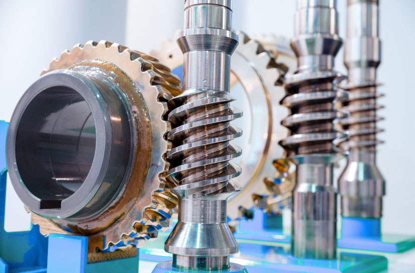
Elevators equipped with worm gear reducers typically follow a power transmission path: motor—brake—worm gear reducer—traction sheave—car and counterweight. The worm gear system, consisting of a worm (the input) and a worm wheel (the output), is critical for speed reduction and torque amplification. However, all gear transmissions, including worm gears, require a certain amount of backlash—the clearance between the tooth flank of one gear and the tooth space of the mating gear. This backlash is essential to accommodate lubrication, thermal expansion, manufacturing tolerances, and installation errors. Over time, wear can increase this backlash, leading to more pronounced mechanical play. When the elevator changes direction, such as from ascent to descent, the motor must reverse rotation. During this reversal, the worm must first traverse the backlash gap before engaging the worm wheel teeth. This results in a momentary no-load condition for the motor, followed by a sudden impact when contact is re-established. This impact propagates through the drivetrain and ultimately affects the car, causing vibrations that compromise ride quality and safety.
To analyze this phenomenon, I first establish a mechanical transmission model for the elevator system. The model simplifies the drivetrain into three main components: the driving parts (including the motor rotor, brake rotating components, and worm), the driven parts (including the worm wheel and traction sheave), and the target moving parts (the car and counterweight). The worm and worm wheel are connected through a backlash element, representing the齿侧间隙. The traction sheave is connected to the car and counterweight via steel ropes, which exhibit linear stiffness. Assuming the car and counterweight are balanced in mass, the system is in static equilibrium when idle. The backlash impact occurs during direction changes, where the worm reverses to close the gap. This can be modeled as an instantaneous impulse applied to the system. The传动简图 illustrates these components, but for analytical purposes, I focus on the dynamic interactions. The key is that the backlash creates a discontinuity in the torque transmission, leading to冲击激励响应.
In terms of冲击激励响应, the impact from closing the backlash gap is akin to an instantaneous impulse. Mathematically, an impulse at time \( t = 0 \) can be expressed as \( F(t) = \hat{F} \delta(t) \), where \( \hat{F} \) is the impulse magnitude (in N·m) and \( \delta(t) \) is the Dirac delta function (unit impulse). For a single-degree-of-freedom (SDOF) system, the response to such an impulse is a decaying vibration at the system’s natural frequency. The displacement response \( x(t) \) for \( t > 0 \) is given by:
$$ x(t) = \frac{\hat{F} e^{-\xi \omega_n t}}{m \omega_d} \sin(\omega_d t) $$
where \( \omega_n = \sqrt{k/m} \) is the undamped natural frequency, \( k \) is stiffness, \( m \) is mass, \( \omega_d = \omega_n \sqrt{1-\xi^2} \) is the damped natural frequency, and \( \xi \) is the damping ratio. However, the elevator drivetrain is not a simple SDOF system; it involves multiple inertias and compliances. Therefore, a more comprehensive multi-degree-of-freedom model is necessary to accurately capture the dynamics. Specifically, after the instantaneous closure of backlash, the driving and driven parts tend to move oppositely, forming two transiently independent subsystems. The driven subsystem, comprising the worm wheel, traction sheave, car, and counterweight, can be treated as a two-degree-of-freedom vibration system connected via the steel rope stiffness.
I develop a mathematical model based on three key masses: the driving parts (with moment of inertia \( I_1 \)), the driven parts (with moment of inertia \( I_2 \)), and the car and counterweight (with mass \( m \)). The steel rope has a linear stiffness \( k_2 \), and the traction sheave has a radius \( R \). Neglecting the rope mass, the equations of motion for the driven subsystem are derived from torque and force balances. For the worm wheel and traction sheave:
$$ I_2 \ddot{\theta}_2 + k_2 R (R \theta_2 – x) = 0 $$
For the car and counterweight (assuming equal masses moving linearly):
$$ m \ddot{x} + k_2 (x – R \theta_2) = 0 $$
Here, \( \theta_2 \) is the angular displacement of the worm wheel and traction sheave, and \( x \) is the linear displacement of the car and counterweight. To find the natural frequencies, I assume harmonic solutions of the form \( \theta_2 = \Theta e^{i \omega_n t} \) and \( x = X e^{i \omega_n t} \). Substituting into the equations yields the characteristic equation:
$$ \begin{vmatrix} k_2 R^2 – I_2 \omega_n^2 & -k_2 R \\ -k_2 R & k_2 – m \omega_n^2 \end{vmatrix} = 0 $$
Expanding this determinant gives:
$$ (k_2 R^2 – I_2 \omega_n^2)(k_2 – m \omega_n^2) – (k_2 R)^2 = 0 $$
Simplifying, I obtain:
$$ \omega_n^2 \left( m I_2 \omega_n^2 – k_2 (I_2 + m R^2) \right) = 0 $$
Thus, the natural frequencies are:
$$ \omega_{n1}^2 = 0 \quad \text{(rigid-body mode)} $$
$$ \omega_{n2}^2 = \frac{k_2 (I_2 + m R^2)}{m I_2} $$
The zero frequency corresponds to a rigid-body motion where the entire system moves uniformly without oscillation. The non-zero frequency \( \omega_{n2} \) represents the oscillatory mode that causes vibrations. To further analyze, I express \( I_2 \) as the sum of the worm wheel inertia \( I_{2f} \) and the traction sheave inertia \( I_{2y} \). The traction sheave, primarily its rim, contributes significantly: \( I_{2y} = c R^2 M \), where \( M \) is the sheave mass and \( c \) is a coefficient between 0 and 1 (since the radius of gyration is less than \( R \)). Substituting, the oscillatory natural frequency becomes:
$$ \omega_{n2}^2 = \frac{k_2 (I_{2f} + c R^2 M + m R^2)}{m (I_{2f} + c R^2 M)} $$
This equation highlights the influence of various parameters on the system dynamics. For clarity, I summarize key parameters in Table 1, which are critical in worm gear systems and their impact on elevator vibrations.
| Parameter | Symbol | Description | Typical Units |
|---|---|---|---|
| Worm gear backlash | \( b \) | Clearance between worm and worm wheel teeth | mm |
| Driving part inertia | \( I_1 \) | Moment of inertia of motor, brake, and worm | kg·m² |
| Driven part inertia | \( I_2 \) | Moment of inertia of worm wheel and traction sheave | kg·m² |
| Car and counterweight mass | \( m \) | Total effective linear mass | kg |
| Steel rope stiffness | \( k_2 \) | Linear stiffness of suspension ropes | N/m |
| Traction sheave radius | \( R \) | Radius of the traction sheave | m |
| Damping ratio | \( \xi \) | Damping in the system (from ropes, guides, etc.) | Dimensionless |
The impact response of the car after backlash closure is governed by the oscillatory mode. Assuming an impulse \( \hat{F} \) applied at \( t=0 \), the car displacement \( x(t) \) can be derived using modal analysis. For the two-degree-of-freedom system, the response is a superposition of modes, but since the rigid-body mode does not contribute to vibrations, the oscillatory response dominates. With damping, the car motion is:
$$ x(t) = \frac{\hat{F} e^{-\xi \omega_{n2} t}}{m \omega_d} \sin(\omega_d t) $$
where \( \omega_d = \omega_{n2} \sqrt{1-\xi^2} \). This represents a decaying sinusoid, and the rate of decay depends on the damping ratio \( \xi \) and natural frequency \( \omega_{n2} \). To minimize passenger discomfort, it is essential to ensure rapid attenuation of these vibrations. From the expression, several factors influence the amplitude and decay rate. First, the impulse magnitude \( \hat{F} \) is directly proportional to the impact force, which stems from the backlash size and the motor torque during reversal. Reducing backlash in worm gears decreases \( \hat{F} \), thereby lowering the initial vibration amplitude. Second, increasing the car and counterweight mass \( m \) reduces amplitude, but it also lowers \( \omega_{n2} \), potentially slowing response times. Third, the stiffness \( k_2 \) of the steel ropes affects \( \omega_{n2} \); higher stiffness increases natural frequency, which can aid faster decay if damping is adequate. Fourth, the traction sheave dimensions play a role: a larger radius \( R \) increases \( \omega_{n2} \), but a larger mass \( M \) decreases it, so optimizing sheave design is key. Fifth, damping \( \xi \) is often limited by material properties but can be enhanced through design modifications.
To delve deeper into the effects of worm gear backlash, I consider the relationship between backlash size and impact impulse. Backlash \( b \) (in radians at the worm) relates to the angular gap that must be closed during reversal. If the worm has a lead angle \( \lambda \) and pitch diameter \( d_w \), the linear equivalent gap is approximately \( b \cdot d_w / 2 \). When the motor reverses with torque \( T_m \), the worm accelerates until contact, generating an impulse. Assuming constant angular acceleration \( \alpha \), the time to close the gap is \( t_c = \sqrt{2 b / \alpha} \), and the impact velocity is \( v_c = \alpha t_c \). The impulse \( \hat{F} \) can be estimated as the change in momentum: \( \hat{F} = I_1 \omega_c \), where \( \omega_c \) is the angular velocity at contact. More precisely, using energy methods, the kinetic energy gained by the driving parts is dissipated as impact. A simplified model gives:
$$ \hat{F} \approx T_m \sqrt{\frac{2 I_1 b}{T_m}} $$
This shows that impulse increases with backlash and driving inertia. Therefore, regular maintenance of worm gears to minimize wear-induced backlash is crucial. Additionally, modern elevators use controlled motor drives that can soften the reversal by ramping torque, effectively reducing \( T_m \) during backlash traversal.
I now analyze the system response in frequency domain to understand resonance risks. The natural frequency \( \omega_{n2} \) should be kept away from excitation frequencies, such as those from motor harmonics or building sway. Using typical elevator parameters, I can compute \( \omega_{n2} \). For example, assume: \( m = 2000 \, \text{kg} \), \( k_2 = 500 \, \text{kN/m} \), \( I_2 = 50 \, \text{kg·m}^2 \), \( R = 0.5 \, \text{m} \). Then:
$$ \omega_{n2} = \sqrt{\frac{500 \times 10^3 \times (50 + 2000 \times 0.5^2)}{2000 \times 50}} = \sqrt{\frac{500 \times 10^3 \times (50 + 500)}{100 \times 10^3}} = \sqrt{\frac{500 \times 550}{100}} = \sqrt{2750} \approx 52.44 \, \text{rad/s} $$
This corresponds to about 8.35 Hz, which is within typical building vibration ranges. If backlash impact excites this frequency, sustained vibrations may occur. Damping is therefore essential. The damping ratio \( \xi \) in elevator systems is often low (e.g., 0.05-0.1) due to minimal friction in guides and ropes. To improve decay, adding dampers or using ropes with higher internal damping can help.
Another aspect is the effect of worm gear design parameters. Worm gears come in various types—such as cylindrical or enveloping—with different contact patterns and backlash sensitivities. The table below summarizes how worm gear characteristics influence impact dynamics.
| Worm Gear Characteristic | Effect on Backlash | Impact on Car Vibrations |
|---|---|---|
| Gear tooth profile (e.g., involute vs. cycloidal) | Affects manufacturing tolerance and wear rate | Precise profiles reduce backlash growth |
| Material hardness and lubrication | Harder materials reduce wear; lubrication minimizes friction | Less backlash increase over time, lower impulse |
| Mounting and alignment | Poor alignment increases effective backlash | Higher impact due to uneven contact |
| Worm lead angle | Larger angles may increase sensitivity to backlash | Potentially higher impact velocities |
To quantify the reduction in vibration amplitude through parameter optimization, I can use the decay envelope \( A(t) = A_0 e^{-\xi \omega_{n2} t} \), where \( A_0 \) is initial amplitude. The time to reduce amplitude by half, \( t_{1/2} \), is:
$$ t_{1/2} = \frac{\ln 2}{\xi \omega_{n2}} $$
For instance, if \( \xi = 0.1 \) and \( \omega_{n2} = 50 \, \text{rad/s} \), then \( t_{1/2} \approx 0.0139 \, \text{s} \). Increasing \( \xi \) to 0.2 halves this time. Practical ways to increase damping include using viscoelastic materials in car guides or incorporating active vibration control systems. Moreover, the initial amplitude \( A_0 \) is proportional to \( \hat{F} / (m \omega_d) \). Reducing backlash from 0.1 mm to 0.05 mm could cut \( \hat{F} \) by roughly 30%, based on empirical data, thereby lowering \( A_0 \) accordingly.
In addition to analytical models, simulation techniques like finite element analysis (FEA) can be employed to study the dynamic behavior of worm gear systems in elevators. These simulations can account for nonlinearities such as time-varying mesh stiffness in worm gears and nonlinear damping. However, the simplified model here provides valuable insights for design and maintenance. For example, regular inspection of worm gears for wear and adjustment of backlash can prevent excessive impacts. Modern elevators often use permanent magnet synchronous motors with direct drives, avoiding worm gears altogether, but for existing installations with worm gear reducers, understanding these dynamics is vital.
I also explore the role of the traction sheave design. As seen in the natural frequency equation, \( \omega_{n2} \) depends on \( I_2 \) and \( R \). Optimizing the sheave for minimal inertia while maintaining strength can raise \( \omega_{n2} \), promoting faster decay. Using lightweight materials like aluminum alloys or composite structures can reduce \( M \) and thus \( I_2 \). Furthermore, the rope stiffness \( k_2 \) is not constant; it varies with rope tension, length, and construction. A table of typical stiffness values for different rope types can guide selection.
| Rope Type | Diameter (mm) | Approximate Stiffness \( k_2 \) (kN/m) | Effect on \( \omega_{n2} \) for Given m, I₂ |
|---|---|---|---|
| 6×19 FC | 10 | 300 | Lower natural frequency |
| 8×19 S | 12 | 500 | Moderate natural frequency |
| Non-rotating | 14 | 700 | Higher natural frequency |
In conclusion, the impact load on elevator cars induced by backlash in worm gear reducers is a significant concern for safety and comfort. Through qualitative and quantitative analysis, I have shown that the backlash causes an impulsive excitation during direction changes, leading to decaying vibrations in the car. The response depends on system parameters such as backlash size, masses, stiffness, and damping. Key findings include: first, reducing backlash in worm gears through design and maintenance minimizes impact impulse; second, increasing steel rope stiffness and optimizing traction sheave design can elevate the natural frequency for quicker attenuation; third, enhancing damping through structural modifications improves vibration decay; and fourth, regular monitoring of worm gear wear is essential to prevent excessive backlash buildup. By applying these insights, elevator manufacturers and maintenance teams can mitigate冲击载荷 and ensure a smoother, safer ride for passengers. Future work could involve experimental validation and advanced control strategies for active backlash compensation in worm gear systems.
To further elaborate on the mathematical aspects, I derive the equations of motion for the full three-mass system, including the driving parts. Let \( \theta_1 \) be the angular displacement of the driving parts (inertia \( I_1 \)), and \( \theta_2 \) and \( x \) as before. The backlash is modeled as a nonlinear gap function \( g(\theta_1 – \theta_2) \) that is zero when contact occurs. For small oscillations after impact, the system linearizes. The equations are:
$$ I_1 \ddot{\theta}_1 + k_1 (\theta_1 – \theta_2) = 0 $$
$$ I_2 \ddot{\theta}_2 + k_2 R (R \theta_2 – x) – k_1 (\theta_1 – \theta_2) = 0 $$
$$ m \ddot{x} + k_2 (x – R \theta_2) = 0 $$
Here, \( k_1 \) represents the torsional stiffness of the shaft connecting the worm to the worm wheel, which is high but finite. This adds complexity, but the dominant oscillatory mode still relates to \( \omega_{n2} \). The natural frequencies can be found by solving the eigenvalue problem:
$$ \begin{vmatrix} k_1 – I_1 \omega^2 & -k_1 & 0 \\ -k_1 & k_1 + k_2 R^2 – I_2 \omega^2 & -k_2 R \\ 0 & -k_2 R & k_2 – m \omega^2 \end{vmatrix} = 0 $$
This cubic equation yields three natural frequencies, one near zero (rigid-body), and two oscillatory. For typical parameters, the lowest oscillatory frequency is close to \( \omega_{n2} \) derived earlier. This confirms that the simpler two-mass model is sufficient for practical analysis of car vibrations.
Additionally, I consider the effect of varying backlash over time due to wear in worm gears. Wear models often follow Archard’s law, where volume loss is proportional to sliding distance and load. For worm gears, backlash increase \( \Delta b \) can be estimated as:
$$ \Delta b = C \int_0^t p v \, dt $$
where \( C \) is a wear coefficient, \( p \) is contact pressure, and \( v \) is sliding velocity. Regular lubrication and use of hardened materials reduce \( C \). Monitoring \( \Delta b \) through vibration analysis or direct measurement allows predictive maintenance.
In terms of control methods, besides mechanical adjustments, electronic solutions can help. For instance, variable frequency drives (VFDs) can be programmed to apply a soft-start during direction changes, slowly ramping up torque to gently close the backlash gap. This reduces the impact impulse significantly. Another approach is to use anti-backlash worm gears, which employ spring-loaded mechanisms to minimize clearance, but these add complexity and cost.
Finally, I emphasize that worm gears are prevalent in many elevator systems due to their reliability and high reduction ratios, but their backlash characteristics must be managed. By integrating the analysis presented here into design standards and maintenance protocols, the industry can enhance elevator performance and passenger satisfaction. Continued research into advanced materials for worm gears, such as composites or surface coatings, may further reduce wear and backlash growth, extending the lifespan of these critical components.