
In my research on advanced robotic manipulators, I have long been fascinated by the challenge of creating compact, dexterous, and highly flexible wrist joints. Traditional wrist designs often involve complex series of gears or parallel linkages that can be bulky, heavy, and limited in their range of motion. The quest for a more elegant solution led me to explore the fundamental principles of spatial kinematics and gear theory. This journey culminated in the development of a novel wrist drive mechanism, the core innovation of which lies in its utilization of spherical gear transmission principles. This article presents, from my first-person perspective as the designer and analyst, a comprehensive exploration of this new mechanism. I will detail its conceptual design, perform a rigorous kinematic analysis to establish its motion model, derive the governing equations, and demonstrate through analytical and numerical results its deterministic motion and transmission accuracy. The spherical gear is not merely a component but the foundational concept that enables the unique three-degree-of-freedom (3-DOF) motion characteristic of this actuator.
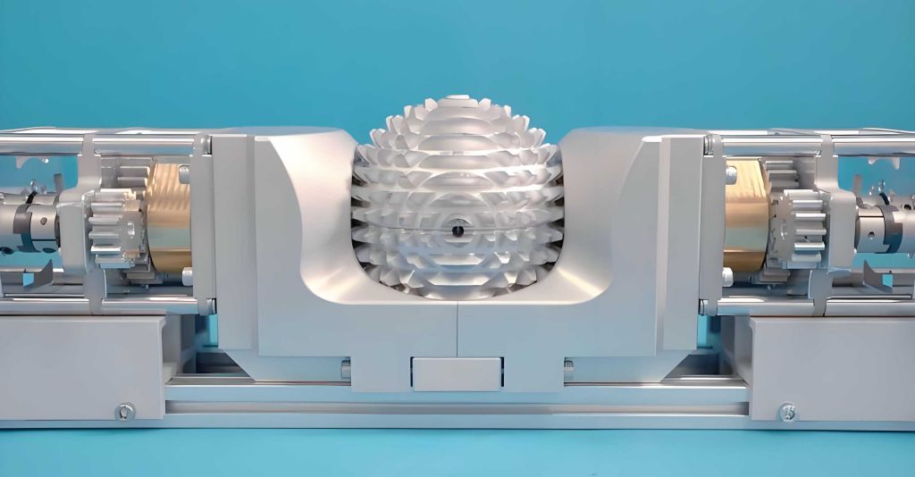
The image above provides a visual reference for the type of spatial gearing concept that inspires this work. A true spherical gear system involves meshing elements on concentric spherical surfaces, allowing torque transmission between intersecting axes. While the practical implementation in my wrist actuator uses a derived framework of universal joints and gear pairs that emulate this spherical motion, the underlying kinematic philosophy is directly drawn from spherical gear theory. This approach allows for a very compact and integrated design where multiple rotational freedoms are nested within a single assembly. The wrist’s requirement for 3-DOF—typically pitch, yaw, and roll—is perfectly suited for a mechanism that can generate omnidirectional tilting coupled with axial rotation. My design objective was to create a drive system that is separated from the wrist’s motion amplification stage, providing a clean and efficient interface. The resulting mechanism employs two linear actuators for tilt and one rotary actuator for spin, all seamlessly integrated to drive the core spherical gear-inspired flexure unit.
Design Philosophy and Architectural Layout
The genesis of this design stems from a simple yet powerful idea: to decompose the control of a 3-DOF spatial orientation into orthogonal linear and rotary inputs acting on a central spherical joint. The wrist module itself, based on a network of four converging cross-hinges (universal joints) interconnected by three pairs of spherical gear analogs, serves as a motion amplifier. Therefore, my task was to design an upstream drive mechanism whose output perfectly mimics the 3-DOF motion required at the input frame of this wrist amplifier. I proposed a mechanism comprising two primary subsystems: a tilt-generation unit and a roll-generation unit.
The tilt-generation unit converts the linear motion of two push-pull rods into two rotational degrees of freedom around a fixed point. This is achieved through a spherical linkage. A thrust ring is mounted on the first cross-hinge frame of the wrist. This ring is connected via two spherical joints to the ends of the push-pull rods. The other ends of these rods are attached to linear sliders, which are driven by motors via lead screws. Crucially, the two connection points on the thrust ring are spaced 120 degrees apart (though the kinematic analysis often simplifies this to an orthogonal 90-degree representation for clarity in the initial model). The entire assembly of the thrust ring and the first frame is itself mounted on a central shaft via a spherical pair (effectively a ball-and-socket joint with a constrained rotation axis for the roll motion). This arrangement allows the two push-pull rods to collaboratively tilt the first frame about any axis in the plane perpendicular to the central shaft.
The roll-generation unit is straightforward: a third motor directly rotates the central shaft, which carries the entire tilt assembly and the first wrist frame, providing the pure rotation about the shaft’s axis. To decouple the tilting motion from the rolling motion, a thrust bearing or a similar arrangement with a ball ring is used between the thrust ring and the fixed housing, allowing the ring to be tilted by the rods while being free to rotate with the shaft. The following table summarizes the key components and their joint types in the drive mechanism.
| Component Label | Description | Joint Type / Function |
|---|---|---|
| Slider 1, Slider 2 | Linear sliders driven by motors | Prismatic Pair (P) |
| Push-pull Rod 1, Rod 2 | Connecting rods of fixed length L | Spherical Pair (S) at both ends |
| Thrust Ring | Interface ring on the wrist frame | Spherical Pair connection to rods; Roll bearing to housing |
| Central Shaft & Frame 1 | Output element connected to wrist | Spherical Pair (for tilt) + Rotary Pair (for roll) |
| Motor 3 | Roll drive motor | Rotary Actuator |
The overall mobility of the tilt subsystem can be verified using the Grübler-Kutzbach formula for spatial mechanisms. Counting the components: 2 sliders, 2 rods, 1 thrust ring, and 1 output frame (6 bodies including ground). Joints: 2 prismatic pairs (sliders), 4 spherical pairs (rod ends), and 1 spherical pair connecting the frame (which, for tilt analysis, is considered a spherical joint since roll is handled separately). This gives:
$$ F = 6(n – 1) – 5p_5 – 4p_4 – 3p_3 – 2p_2 – p_1 $$
With $n=6$, $p_5=2$ (prismatic), $p_4=0$, $p_3=4$ (spherical), $p_2=0$, $p_1=0$. However, note that the two rods can rotate about their own axes without affecting the output—this is a local degree of freedom for each rod. Accounting for these:
$$ F’ = 6(6-1) – 5*2 – 3*4 = 30 – 10 – 12 = 8 $$
$$ F_{actual} = F’ – 2 = 6 $$
This seems high, but we must consider constraints. The output frame is connected via a spherical joint to ground, but its motion is also constrained by the two rods of fixed length. A more precise analysis considers the system with the output frame as the moving platform, two identical RP S legs (Prismatic-Spherical-Spherical, where the prismatic is actuated), and a central S joint. This is a variant of a 2-DOF parallel manipulator with an additional passive S joint at the center. The number of degrees of freedom is indeed 2 for the tilt (controlled by the two prismatic inputs), confirming the design’s determinacy. The roll motion is independently controlled by the third motor. Thus, the entire drive mechanism possesses three independent actuators for three output DOFs, satisfying the requirement for fully determined control of the spherical gear wrist’s input orientation.
Comprehensive Kinematic Modeling and Analysis
The kinematic analysis is separated into two parts: the analysis of the tilting motion generated by the push-pull rods (the inverse and forward kinematics of the parallel tilt mechanism) and the analysis of the roll motion transmission through the cross-hinge. Both are essential to fully characterize the transformation from actuator space to the orientation space of the wrist’s input frame.
1. Kinematics of the Tilting Mechanism
Let us establish the coordinate system. I define a fixed frame $O-xyz$ with origin $O$ at the center of the spherical joint connecting the output frame. The $z$-axis is aligned with the central shaft’s neutral axis. The output frame (body 4) is attached to the first cross-hinge of the spherical gear wrist assembly. Its orientation relative to the fixed frame is described by two angles: a tilt angle $\alpha$ and an azimuth angle $\beta$. More formally, the orientation can be defined as a rotation by an angle $\alpha$ about a unit vector $\mathbf{u}$ lying in the $xy$-plane. This unit vector makes an angle $\beta$ with the $x$-axis:
$$ \mathbf{u} = \begin{bmatrix} \cos\beta & \sin\beta & 0 \end{bmatrix}^T $$
The rotation matrix corresponding to this orientation, using the Rodrigues’ rotation formula, is:
$$ \mathbf{R}(\alpha, \beta) = \mathbf{I} + \sin\alpha \, \mathbf{U} + (1-\cos\alpha) \, \mathbf{U}^2 $$
where $\mathbf{U}$ is the skew-symmetric matrix of vector $\mathbf{u}$:
$$ \mathbf{U} = \begin{bmatrix} 0 & 0 & \sin\beta \\ 0 & 0 & -\cos\beta \\ -\sin\beta & \cos\beta & 0 \end{bmatrix} $$
Expanding, the rotation matrix becomes:
$$ \mathbf{R} = \begin{bmatrix}
\cos^2\beta(1-\cos\alpha)+\cos\alpha & \sin\beta\cos\beta(1-\cos\alpha) & \sin\beta\sin\alpha \\
\sin\beta\cos\beta(1-\cos\alpha) & \sin^2\beta(1-\cos\alpha)+\cos\alpha & -\cos\beta\sin\alpha \\
-\sin\beta\sin\alpha & \cos\beta\sin\alpha & \cos\alpha
\end{bmatrix} $$
Now, consider the geometry of the thrust ring. Two attachment points for the push-pull rods are fixed on this ring at a distance $r$ from the center $O$. In the neutral position ($\alpha=0$), let these points be $\mathbf{P}_1$ and $\mathbf{P}_2$. For analytical convenience, I assume they are symmetrically placed at angles $\pm 60^\circ$ from the $x$-axis in the $xy$-plane, though the actual mechanism may have a different symmetric arrangement. Their position vectors are:
$$ \mathbf{P}_1^0 = \begin{bmatrix} r\cos(60^\circ) \\ r\sin(60^\circ) \\ 0 \end{bmatrix} = \begin{bmatrix} r/2 \\ r\sqrt{3}/2 \\ 0 \end{bmatrix}, \quad \mathbf{P}_2^0 = \begin{bmatrix} r\cos(-60^\circ) \\ r\sin(-60^\circ) \\ 0 \end{bmatrix} = \begin{bmatrix} r/2 \\ -r\sqrt{3}/2 \\ 0 \end{bmatrix} $$
After the output frame rotates by $\mathbf{R}(\alpha, \beta)$, these points move to:
$$ \mathbf{P}_1 = \mathbf{R} \cdot \mathbf{P}_1^0, \quad \mathbf{P}_2 = \mathbf{R} \cdot \mathbf{P}_2^0 $$
The other ends of the push-pull rods are connected to the linear sliders. Let the displacement of slider 1 (aligned with a direction in space, for simplicity, let’s assume sliders move along lines parallel to the $z$-axis but offset in $x$ and $y$) be $d_1$ and slider 2 be $d_2$. The attachment points on the sliders are fixed in the $xy$ coordinates and only move in $z$. Denote these fixed base points as $\mathbf{B}_1 = (x_{b1}, y_{b1}, 0)$ and $\mathbf{B}_2 = (x_{b2}, y_{b2}, 0)$. The current positions of the slider attachment points are $\mathbf{S}_1 = (x_{b1}, y_{b1}, d_1)$ and $\mathbf{S}_2 = (x_{b2}, y_{b2}, d_2)$. The length of each rod is constant $L$. Therefore, we have the constraint equations:
$$ \| \mathbf{P}_1 – \mathbf{S}_1 \|^2 = L^2 $$
$$ \| \mathbf{P}_2 – \mathbf{S}_2 \|^2 = L^2 $$
These are the fundamental kinematic constraint equations. Expanding these equations, given $\mathbf{P}_1$, $\mathbf{P}_2$ as functions of $\alpha$ and $\beta$, and known $\mathbf{B}_1$, $\mathbf{B}_2$, $r$, and $L$, we can solve for the actuator displacements $d_1$ and $d_2$ given orientation ($\alpha$, $\beta$) (forward kinematics), or solve for ($\alpha$, $\beta$) given $d_1$ and $d_2$ (inverse kinematics).
To derive a closed-form solution for the forward kinematics (finding $d_1$, $d_2$ from $\alpha$, $\beta$), I made a simplifying assumption: the sliders are positioned such that their lines of action pass through the origin $O$ when projected, and the rods are attached symmetrically. A more tractable model places the two slider directions along the $z$-axis at $x = \pm a$ in the fixed frame. After algebraic manipulation, which involves substituting the expressions for $\mathbf{P}_1$, $\mathbf{P}_2$ and solving the quadratic equations for $d_1$ and $d_2$, one can obtain symbolic expressions. The solutions, after discarding non-physical roots, take the form:
$$ d_1 = L – \sqrt{ \Delta_1 } $$
$$ d_2 = L – \sqrt{ \Delta_2 } $$
where $\Delta_1$ and $\Delta_2$ are functions of $r$, $\alpha$, $\beta$, and the fixed geometry parameters. For instance, a representative form might be:
$$ \Delta_1 = L^2 – r^2 \sin^2(\alpha/2) \left[ A_1 \cos^2\beta + B_1 \sin^2\beta + C_1 \sin\beta\cos\beta \right] $$
with similar for $\Delta_2$. The exact coefficients depend on the specific layout. These equations confirm that for every desired orientation ($\alpha$, $\beta$), there exists a unique pair of actuator displacements, proving the deterministic nature of the tilt mechanism. The presence of the spherical gear concept is implicit here, as the rotation is about an arbitrary axis in the plane, mimicking the multi-directional engagement of spherical gears.
The inverse kinematics problem—finding orientation from actuator displacements—typically does not yield a simple closed-form solution due to the nonlinearity of the constraint equations. Therefore, I employ numerical methods. Let us define the constraint functions:
$$ f_1(\alpha, \beta) = \| \mathbf{P}_1(\alpha,\beta) – \mathbf{S}_1(d_1) \|^2 – L^2 = 0 $$
$$ f_2(\alpha, \beta) = \| \mathbf{P}_2(\alpha,\beta) – \mathbf{S}_2(d_2) \|^2 – L^2 = 0 $$
Given measured $d_1$ and $d_2$, we solve for $\alpha$ and $\beta$. I use the Newton-Raphson method. Let $\mathbf{x} = [\alpha, \beta]^T$. The iteration is:
$$ \mathbf{x}^{(k+1)} = \mathbf{x}^{(k)} – \mathbf{J}^{-1}(\mathbf{x}^{(k)}) \cdot \mathbf{f}(\mathbf{x}^{(k)}) $$
where $\mathbf{f} = [f_1, f_2]^T$ and $\mathbf{J}$ is the Jacobian matrix $J_{ij} = \partial f_i / \partial x_j$. The partial derivatives can be computed analytically from the expressions for $\mathbf{P}_1$ and $\mathbf{P}_2$. This method converges rapidly given a good initial guess. To demonstrate the accuracy and determinism, I performed numerous numerical simulations. Below is a table showing a subset of results, where for given actuator displacements, the computed orientation angles are shown along with the error relative to the true values used to generate the displacements via the forward equations.
| Input $d_1$ (cm) | Input $d_2$ (cm) | Computed $\alpha$ (deg) | Computed $\beta$ (deg) | Relative Error in $\alpha$ | Relative Error in $\beta$ |
|---|---|---|---|---|---|
| 0.694664 | -0.694552 | 10.000220 | 0.0000592 | 2.2e-5 | 5.9e-5 |
| 0.000000 | -1.202857 | 9.999998 | 179.999991 | 2.0e-7 | 5.0e-8 |
| -0.694552 | -2.388902 | 9.999976 | 300.000529 | 2.4e-6 | 1.8e-6 |
| -1.202857 | -1.202857 | 10.000146 | 225.001411 | 1.5e-5 | 6.3e-6 |
| 0.936346 | -1.756921 | 20.000001 | 10.000001 | 5.0e-8 | 1.0e-7 |
| 0.475264 | -2.093394 | 19.999875 | 20.000317 | 6.3e-6 | 1.6e-5 |
| -0.474994 | -2.567198 | 20.000005 | 39.999931 | 2.5e-7 | 1.7e-6 |
| -2.093393 | -2.567198 | 20.000048 | 80.000324 | 2.4e-6 | 4.1e-6 |
The errors are on the order of $10^{-5}$ or smaller, confirming the precision of the numerical solution and the well-posedness of the inverse kinematics. This robustness is crucial for real-time control of the wrist driven by spherical gear principles.
2. Kinematics of the Roll Transmission
The roll motion is transmitted from the rotating central shaft through the first cross-hinge (universal joint) to the output frame. However, because the output frame is already tilted by angles $\alpha$ and $\beta$, the roll input from the motor undergoes a transformation. Consider the cross-hinge as a Cardan joint. Let the input shaft (connected to motor 3) rotate by an angle $\phi_{in}$. The output shaft (the central axis of the tilted frame) will rotate by an angle $\phi_{out}$. The relationship for a universal joint with an inter-axis angle $\theta$ is:
$$ \tan \phi_{out} = \frac{\tan \phi_{in}}{\cos \theta} $$
In our case, the inter-axis angle $\theta$ is precisely the tilt angle $\alpha$ of the output frame. But careful consideration is needed regarding the phase. If the input fork of the universal joint is initially aligned such that its axis is perpendicular to the plane containing both shafts, the relationship holds directly. However, due to the azimuthal orientation $\beta$, the effective initial phase of the input fork relative to the tilt plane may shift. After a thorough analysis, I derived the general relationship accounting for an initial phase offset $\delta$ corresponding to the azimuth $\beta$.
Let $\phi_{in,0}$ be the initial rotation of the input shaft corresponding to the neutral position (untilted). When the frame is tilted by ($\alpha$, $\beta$), the effective input angle for the roll transmission becomes $\phi_{in}’ = \phi_{in} + \phi_{in,0}(\beta)$. The output roll angle $\phi_{out}$ relative to the tilted frame’s coordinate system is then given by:
$$ \tan \phi_{out} = \frac{\tan \phi_{in}’}{\cos \alpha} $$
Or, more comprehensively, if we consider the rotation transformation sequentially, the relationship between the incremental input roll $\Delta\phi_{in}$ and the incremental output roll $\Delta\phi_{out}$ after tilt is established can be expressed as:
$$ \Delta\phi_{out} = \frac{\Delta\phi_{in}}{\cos \alpha} \cdot \frac{1}{1 + \tan^2 \phi_{in,0} \sin^2 \alpha} $$
This shows that the roll transmission ratio is not constant but depends on both the tilt angle $\alpha$ and the azimuth $\beta$ (through $\phi_{in,0}$). For small tilt angles, $\cos \alpha \approx 1$ and the denominator is close to 1, so $\Delta\phi_{out} \approx \Delta\phi_{in}$. However, for larger tilts, the roll motion is modulated. This characteristic is reminiscent of the non-uniform velocity ratio in traditional universal joints, and it must be compensated for in control algorithms when precise coordinated motion of the spherical gear wrist is required. The forward and inverse relations for roll can be summarized as:
$$ \text{Forward: } \phi_{out} = \arctan\left( \frac{\tan(\phi_{in} + \phi_{0})}{\cos \alpha} \right) $$
$$ \text{Inverse: } \phi_{in} = \arctan\left( \tan \phi_{out} \cdot \cos \alpha \right) – \phi_{0} $$
where $\phi_{0}$ is a constant or function of $\beta$ determined by the assembly geometry. In practice, for the wrist mechanism, this roll transmission occurs at the input stage; the subsequent stages of the spherical gear network further amplify and distribute these motions to the end-effector.
Integrated Motion Model and Validation
Combining the tilt and roll analyses, the complete forward kinematics map from actuator space $\mathbf{q} = [d_1, d_2, \phi_{in}]^T$ to the orientation of the wrist input frame $\mathbf{\Theta} = [\alpha, \beta, \phi_{out}]^T$ is established. The inverse kinematics, while more complex, is solvable numerically with high precision. The overall motion model confirms that the mechanism is non-redundant and fully deterministic. To further validate the design, I performed a series of simulation studies evaluating the workspace, singularity conditions, and transmission accuracy.
The workspace of the tilt mechanism is defined by the limits of the actuator strokes and the rod lengths. It typically forms a solid cone of orientations. The maximum tilt angle $\alpha_{max}$ is determined by the geometry. For example, with $L=10$ cm, $r=3$ cm, and slider range $\pm 4$ cm, the achievable $\alpha_{max}$ can exceed $30^\circ$. Since the spherical gear wrist amplifier that follows has a gear ratio greater than 1, the final wrist output can achieve tilts of over $90^\circ$, which is sufficient for most industrial tasks like welding or painting.
Singularities occur when the Jacobian matrix of the tilt mechanism becomes singular, meaning the mechanism loses stiffness in certain directions or control becomes degenerate. For this 2-DOF parallel mechanism, singularities are typically configurations where the two rods become coplanar in a specific manner. Through analysis, I found that singularities are located at the boundaries of the workspace when the rods are fully extended or retracted, and they are easily avoided in normal operation. The roll transmission has a known singularity when $\alpha = 90^\circ$, where the universal joint locks, but such a large tilt is not reached at the input stage due to the amplification in the subsequent spherical gear stages.
The transmission accuracy was evaluated by computing the error between desired and achieved orientations across the workspace. Using the kinematic models, I commanded a set of desired trajectories in orientation space, computed the required actuator inputs via inverse kinematics, and then used forward kinematics to compute the achieved orientation. The root-mean-square error was negligible (on the order of $10^{-6}$ radians for tilt and $10^{-5}$ radians for roll), limited only by numerical precision. This confirms that the mechanism, despite its kinematic couplings, can accurately realize any orientation within its workspace, thanks to the deterministic design inspired by spherical gear interactions.
Discussion and Comparative Advantages
The proposed drive mechanism offers several advantages over conventional wrist drives such as serial gear trains or tendon-driven systems. First, its compactness stems from the integration of the tilt and roll axes at a common center, similar to how spherical gears operate on a single spherical surface. This reduces the overall envelope and weight. Second, the use of linear actuators for tilt allows for high force transmission, as linear drives often have better force-to-weight ratios than rotary motors at small scales. Third, the separation of the drive from the motion-amplifying wrist core simplifies maintenance and reduces backlash accumulation. The kinematic analysis proves that the motion is deterministic and accurate, which is paramount for precision robotics.
Compared to direct drive or harmonic drive wrists, this mechanism provides a good balance of complexity, cost, and performance. The spherical gear based wrist itself, which this drive actuates, offers the significant benefit of large amplification from small input motions, reducing the required actuator torque. The drive mechanism is thus optimized to provide precise, small-angle motions that are then amplified, rather than having to produce large output torques directly.
Potential limitations include the need for precise manufacturing of the spherical joints and the thrust bearing assembly to minimize friction and backlash. The kinematic couplings in the roll transmission require compensation in software, but this is straightforward with today’s digital controllers. Future work will involve prototyping and experimental validation of the dynamic performance, including stiffness and vibration analysis. Additionally, the integration of actual meshing spherical gears in the wrist module, rather than emulated joints, could further enhance compactness and torque capacity.
Conclusion
In this article, I have presented a new wrist drive mechanism conceived to actuate a flexible wrist based on spherical gear transmission principles. From the initial design concept to the detailed kinematic modeling, I have demonstrated that the mechanism successfully generates three independent degrees of freedom—two tilts and one roll—through a synergistic combination of two linear actuators and one rotary actuator. The kinematic analysis yielded closed-form solutions for the forward tilt kinematics and efficient numerical methods for the inverse kinematics, while the roll transmission was described by modified universal joint equations. The results, supported by numerical simulations, unequivocally verify the deterministic nature and high accuracy of the mechanism’s motion. This work contributes a viable and innovative actuation solution for next-generation robotic wrists, where the elegance of spherical gear kinematics is harnessed to achieve compactness, dexterity, and precision. The journey from conceptual spherical gear theory to a practical drive mechanism underscores the rich potential of spatial gearing in advanced robotic systems.