
As a researcher in the field of gear mechanisms, I have long been fascinated by the potential of spherical gears to revolutionize motion transmission in multi-degree-of-freedom systems. Traditional gear systems, such as cylindrical gears, bevel gears, and non-cylindrical gears, are limited to a single degree of freedom, transmitting rotation only between axes with fixed relative positions. In contrast, the spherical gear offers two degrees of freedom, enabling the transmission of two-dimensional rotational motion. This capability mirrors the natural articulation found in biological joints, making spherical gears ideal for applications like bionic robotic joints, flexible wrists, and spatial orientation platforms. However, despite being invented over a decade ago, spherical gears with discretely distributed teeth on a spherical surface have not seen widespread adoption due to inherent transmission inaccuracies and manufacturing complexities. This article, based on my foundational research, proposes a novel annular involute spherical gear mechanism that overcomes these limitations. I will delve into the transmission theory, structural and installation characteristics, and motion analysis of spherical gears, aiming to provide a comprehensive theoretical framework for this promising technology.
The concept of a spherical gear mechanism is visually represented above. It consists of two spherical gears in mesh, each capable of rotational motion about multiple axes. To understand the spherical gear fully, let us first define some core concepts derived from planar gear theory but extended to the spherical domain. The polar axis is a line passing through the sphere’s center and perpendicular to the plane of the tooth ring; it also serves as the rotational axis during manufacturing. A tooth ring is the annular body generated by revolving a planar tooth profile around the polar axis. Spherical gears are categorized into two types: the convex spherical gear, where the polar axis terminates at a protruding columnar tooth body, and the concave spherical gear, where the polar axis ends in a recessed pit. Other key spheres include the tip sphere (from the addendum circle), root sphere (from the dedendum circle), pitch sphere (from the pitch circle), and base sphere (from the base circle). The meshing cone is the locus of contact points between two engaged spherical gears. These definitions are crucial for analyzing the spherical gear’s unique geometry and kinematics.
The heart of the spherical gear’s functionality lies in its meshing principle. To eliminate the transmission errors prevalent in earlier discrete-tooth spherical gears, I propose generating the tooth profile as an annular involute surface. This generation process is mathematically described as follows: Consider a generating line R–K and a base circle in a plane P containing the polar axis. Points A and B are the intersections of the base circle with the polar axis. As the generating line rolls without slip on the base circle, while the entire plane P rotates about the polar axis, any point on the generating line traces out a tooth flank surface. The collective trace of all points on the base circle forms the base sphere. Consequently, the tooth profile in any cross-section containing the polar axis is an involute curve. The ensemble of these involutes creates a continuous annular surface, ensuring smooth and precise meshing.
The meshing characteristics of a pair of spherical gears are distinctive. During operation, the two pitch spheres roll purely against each other without sliding. This results in point contact between the tooth flanks, except when the polar axes align—at that instant, the contact extends to a circular line due to the parallelism of the tooth ring planes. Since the tooth profile in any polar-axis section matches that of a spur gear, the spherical gears can engage from any direction relative to the polar axis. This allows the pitch spheres to roll purely in any arbitrary direction, enabling full-range relative swing between the polar axes. Critically, the polar axes and the sphere centers always lie in a common plane, which is also the normal plane to the tooth profiles. The contact point moves along the line of action within this plane, and the collection of all contact points forms two oppositely pointed conical surfaces—the meshing cones.
For proper engagement, spherical gears must satisfy specific conditions analogous to spur gears but adapted for their spherical nature. Because meshing occurs in the normal plane, the correct meshing conditions involve the normal module and pressure angle:
- $$ m_{n1} = m_{n2} $$
- $$ \alpha_{n1} = \alpha_{n2} $$
where $m_n$ is the normal module and $\alpha_n$ is the normal pressure angle, both standardized. Additionally, spherical gears must be paired correctly: one gear must have its polar axis passing through the center of a tooth space (concave type), and the other must have its polar axis passing through the center of a tooth tip (convex type). This complementary geometry is essential for assembly and continuous meshing.
The contact ratio, or重合度, for spherical gears is calculated similarly to spur gears, as the meshing occurs in the normal plane. Using the concept of an equivalent spur gear (the virtual gear whose teeth match the spherical gear’s normal section), the contact ratio $\epsilon$ is:
$$ \epsilon = \frac{1}{2\pi} \left[ z_{v1} (\tan \alpha_{va1} – \tan \alpha’) + z_{v2} (\tan \alpha_{va2} – \tan \alpha’) \right] $$
where $z_{v1}$ and $z_{v2}$ are the equivalent tooth numbers of the two spherical gears, $\alpha_{va1}$ and $\alpha_{va2}$ are the tip pressure angles of the equivalent gears, and $\alpha’$ is the operating pressure angle. This formula ensures that multiple teeth are in contact simultaneously, promoting smooth motion transmission.
Like cylindrical gears, spherical gears are susceptible to undercutting during generation cutting. To avoid this, profile shifting (变位修正) can be applied. By adjusting the relative position between the gear blank and the cutting tool, a modified spherical gear is produced. The minimum tooth number to avoid undercutting and the minimum shift coefficient directly transfer from spur gear theory. The shift coefficients $x_1$ and $x_2$ modify the tooth thickness and mesh geometry, allowing for design flexibility and improved strength. The following table summarizes key parameters for spherical gear design, comparing them with standard spur gear parameters for clarity.
| Parameter | Spherical Gear | Spherical Gear Symbol | Spur Gear (Equivalent) | Spur Gear Symbol |
|---|---|---|---|---|
| Module | Normal Module | $m_n$ | Module | $m$ |
| Pressure Angle | Normal Pressure Angle | $\alpha_n$ | Pressure Angle | $\alpha$ |
| Tooth Number | Equivalent Tooth Number | $z_v$ | Tooth Number | $z$ |
| Pitch Diameter | Pitch Sphere Diameter | $d_p$ | Pitch Diameter | $d$ |
| Base Diameter | Base Sphere Diameter | $d_b$ | Base Diameter | $d_b$ |
| Contact Ratio | $\epsilon$ (from normal plane) | $\epsilon$ | Contact Ratio | $\epsilon$ |
| Profile Shift | Normal Shift Coefficient | $x_n$ | Shift Coefficient | $x$ |
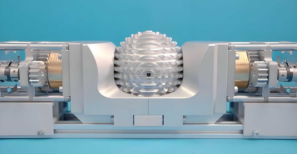
The structure and installation of spherical gears impose unique constraints. Viewed from the polar axis, the teeth appear as concentric rings on a spherical cap, resembling lunar craters. As noted, a concave spherical gear has a central凹坑 along its polar axis, while a convex spherical gear has a protruding齿顶. This dichotomy necessitates paired usage; two identical spherical gears cannot mesh. Moreover, during operation, only the sphere centers remain fixed relative to each other, while the spheres themselves can swing about two perpendicular axes. Therefore, each spherical gear must be mounted on a two-degree-of-freedom gimbal (十字框架), as illustrated conceptually in the image. The input and output shafts are located outside the gimbal plane, with only the teeth on the inner hemisphere engaged. This configuration limits the swing angle of a single spherical gear to typically less than ±90°, so teeth are only distributed on a spherical cap rather than the entire sphere. Installation is possible only when the polar axes are collinear initially, allowing the paired gears to be assembled correctly. Despite these constraints, the spherical gear mechanism benefits from the separability property of involute gears: small errors in the center distance (sphere center separation) do not affect the meshing law, ensuring robustness against assembly inaccuracies.
To analyze the motion of spherical gears, I establish a coordinate system as follows: Let two hemispheres represent the pitch spheres of the spherical gears (for standard spherical gears, these are the pitch spheres). During motion, the pitch spheres undergo pure rolling. This spherical motion can be decomposed into rotations about two mutually perpendicular axes passing through each sphere’s center. For a fixed axis orientation, the spherical gear pair behaves like a spur gear pair, giving the angular relationship:
$$ \frac{\phi_2}{\phi_1} = -\frac{z_1}{z_2} $$
where $\phi_1$ and $\phi_2$ are the rotation angles of the driving and driven gears about their respective instantaneous axes, and $z_1$, $z_2$ are the equivalent tooth numbers. Alternatively, the motion can be described using two component rotations per gear about body-fixed axes. Let the driving gear’s component rotations be $\theta_{x1}$ about the X-axis and $\theta_{y1}$ about the Y-axis, and similarly $\theta_{x2}$, $\theta_{y2}$ for the driven gear. These components are provided by independent actuators. The combined effect equates to a single rotation from an initial position to a new orientation. The relationship between the component angles and the overall rotation angles $\Phi_1$ and $\Phi_2$ can be derived using rotation matrices.
Consider the output shaft’s initial position vector $\vec{r_0} = (x_0, y_0, z_0)$. First, rotate by $\theta_y$ about the Y-axis to $\vec{r’}$, then by $\theta_x$ about the X-axis to $\vec{r}$. The transformation is:
$$ \vec{r} = R_x(\theta_x) R_y(\theta_y) \vec{r_0} $$
where the rotation matrices are:
$$ R_y(\theta_y) = \begin{bmatrix} \cos \theta_y & 0 & \sin \theta_y \\ 0 & 1 & 0 \\ -\sin \theta_y & 0 & \cos \theta_y \end{bmatrix}, \quad R_x(\theta_x) = \begin{bmatrix} 1 & 0 & 0 \\ 0 & \cos \theta_x & -\sin \theta_x \\ 0 & \sin \theta_x & \cos \theta_x \end{bmatrix} $$
The direction cosines of the output shaft in the new position relative to the X-axis can be computed. For motion in the normal plane (when the polar axes are aligned), the transmission is ideal with constant velocity ratio. However, for motion in other planes, the instantaneous transmission ratio may vary because the tooth profile in that plane is not a perfect involute. This leads to a detailed kinematic analysis. Let $\psi_1$ and $\psi_2$ denote the rotation angles of the driving and driven gears about their respective polar axes for a given swing direction. The relationship between $\psi_1$, $\psi_2$ and the component angles $\theta_x$, $\theta_y$ is nonlinear. For instance, from the transformation, we can derive:
$$ \psi_2 = \arctan\left( \frac{\sin \theta_x \cos \theta_y}{\cos \theta_x} \right) \quad \text{for specific configurations} $$
This indicates that when the spherical gear moves in a non-normal plane, the transmission ratio is not constant, introducing kinematic complexity. The following table outlines key motion parameters and their relationships for spherical gears.
| Parameter | Symbol | Description | Relationship/Equation |
|---|---|---|---|
| Driving Gear Rotation | $\phi_1$ | Rotation about instantaneous axis | $\phi_1 = f(\theta_{x1}, \theta_{y1})$ |
| Driven Gear Rotation | $\phi_2$ | Rotation about instantaneous axis | $\phi_2 = -\frac{z_1}{z_2} \phi_1$ (for aligned axes) |
| X-axis Component | $\theta_x$ | Rotation about body-fixed X-axis | From actuator input |
| Y-axis Component | $\theta_y$ | Rotation about body-fixed Y-axis | From actuator input |
| Output Shaft Direction | $\vec{d}$ | Unit vector in new orientation | $\vec{d} = R_x(\theta_x) R_y(\theta_y) \vec{d_0}$ |
| Instantaneous Transmission Ratio | $i$ | Ratio of angular velocities | $i = \frac{d\phi_2/dt}{d\phi_1/dt}$, variable in general plane |
| Swing Angle Limit | $\Theta_{\text{max}}$ | Maximum swing due to gimbal | Typically $|\Theta| < 90^\circ$ |
The motion analysis underscores that while spherical gears enable versatile multi-directional transmission, their kinematic behavior is more complex than conventional gears. The variable transmission ratio in non-normal planes must be accounted for in precision applications. However, for motions primarily within the normal plane or with small deviations, the spherical gear approximates constant-ratio transmission. This analysis provides a foundation for designing control systems for spherical gear-driven mechanisms, such as robotic wrists or orientation platforms.
In conclusion, spherical gear technology represents a frontier in gear transmission theory with vast potential. My research on the annular involute spherical gear addresses critical issues of precision and manufacturability that hindered earlier designs. The spherical gear’s ability to transmit two-dimensional motion makes it uniquely suited for advanced applications beyond traditional gearing. For instance, in bionics, spherical gears can serve as joint mechanisms in humanoid robots (e.g., hip or shoulder joints), prosthetic limbs, or flexible manipulator arms. In industrial automation, they could enhance the dexterity of robotic wrists for painting or assembly. In aerospace and defense, spherical gears might be used in radar antenna steering systems or spatial simulators. However, several challenges remain for widespread adoption. Further research is needed into strength design, efficiency, advanced manufacturing techniques, materials, heat treatment, and the impact of backlash on transmission accuracy. The meshing theory for spherical gears under load, including contact stress and wear analysis, requires development. Additionally, optimizing the tooth profile for improved load distribution and noise reduction is an open area. From a manufacturing perspective, precision machining of the annular involute surfaces necessitates specialized equipment, possibly involving multi-axis CNC grinding or additive manufacturing. As these technical hurdles are overcome, I anticipate spherical gears will find increasing use in any application demanding precise control of spatial orientation with compact, robust transmission elements. The journey of gear technology, spanning centuries, continues to evolve, and the spherical gear is poised to be a significant chapter in that story, enabling machines to move with the fluidity and adaptability of living organisms.
To facilitate design, here is a consolidated list of key formulas for spherical gears, derived from the principles discussed:
- Equivalent Tooth Number: For a spherical gear with nominal tooth number $z$, the equivalent tooth number $z_v$ for normal plane calculations is $z_v = z / \cos^3 \beta$, where $\beta$ is the helix angle (zero for straight teeth).
- Base Sphere Diameter: $$ d_b = d_p \cos \alpha_n $$ where $d_p$ is the pitch sphere diameter and $\alpha_n$ is the normal pressure angle.
- Center Distance (Sphere Center Separation): $$ a = \frac{d_{p1} + d_{p2}}{2} $$ subject to slight adjustments due to separability.
- Profile Shift for Avoidance of Undercutting: The minimum shift coefficient $x_{\text{min}}$ for equivalent tooth number $z_v$ is: $$ x_{\text{min}} = \frac{17 – z_v}{17} $$ (using the analog of the spur gear formula with 17 as the minimum tooth number for no undercutting).
- Tooth Thickness on Pitch Sphere: $$ s_p = \frac{\pi m_n}{2} + 2 x_n m_n \tan \alpha_n $$ where $x_n$ is the normal shift coefficient.
- Kinematic Relation for Aligned Axes: $$ \omega_2 / \omega_1 = – z_1 / z_2 $$ where $\omega$ denotes angular velocity.
These formulas, combined with the tables and analysis provided, form a toolkit for engineers and researchers working with spherical gears. As I continue to explore this field, I believe that collaborative efforts across disciplines—mechanical engineering, materials science, robotics, and control theory—will unlock the full potential of spherical gear transmissions, leading to innovative machines that transcend traditional motion constraints.