
In the realm of space exploration, Mars sampling represents a critical endeavor for understanding planetary evolution, potential habitability, and resource utilization. Traditional joint-link manipulators, while effective, often suffer from complexities in control, heavy mass, and limited flexibility, posing challenges for lightweight rover-based missions. To address these limitations, we propose a novel flexible arm utilizing involute spherical gear transmission. This design aims to achieve multi-degree-of-freedom motion with minimal actuators, enhanced dexterity, and reduced weight, making it ideal for extraterrestrial sampling tasks. Throughout this paper, we will delve into the working principles, detailed design of the spherical gear system, kinematic analysis, control strategy, and potential applications, emphasizing the core role of the spherical gear in enabling this innovative mechanism.
The flexible arm is conceived as a modular system comprising four primary units: the drive unit, steering unit, arm extension unit, and end-effector unit. The arm extension unit forms the backbone, consisting of five pairs of involute spherical gears connected in series via a planetary gear train configuration. This arrangement allows for compound motion, including pitch, yaw, and rotation along the longitudinal axis. The steering unit employs a spatial eight-bar mechanism with two thrust rods and spherical pairs to orient the entire arm, while the drive unit integrates three motors for actuation. The end-effector is a gripper mechanism for sample acquisition, powered by the rotational degree of freedom transmitted through the spherical gear chain. A key advantage is the rear placement of all motors, minimizing moving mass and inertia. The entire system is controlled wirelessly, facilitating remote operation in challenging environments like Mars.
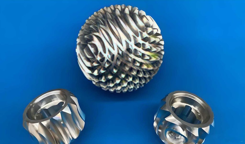
The heart of this flexible arm lies in the innovative involute spherical gear transmission. Unlike conventional gears or existing spherical gear designs, our spherical gear features multiple rings of teeth distributed along latitudes on a spherical cap. Each tooth is shaped similarly to a standard involute cylindrical gear tooth, but arranged concentrically. Adjacent rings have different tooth counts, with tooth cores connecting neighboring teeth to enhance strength. This design allows for smooth engagement and disengagement during articulation. The spherical gear pair enables two rotational degrees of freedom: relative rotation about the common center (like a universal joint) and meshing transmission for torque transfer. The meshing principle ensures that contact occurs along a conical surface, with the pitch circle defined by the intersection of the pitch sphere and the engagement cone.
To understand the kinematics, consider the arm extension unit with n pairs of spherical gears. Each pair behaves as a planetary gear set, where the central spherical gear (sun gear) and the planetary spherical gear are connected by a carrier. When the carrier is tilted, it induces a relative angular displacement between gears. For the series chain, the total output yaw/pitch angle β at the end-effector is the sum of contributions from each stage. Assuming identical spherical gear radii r for simplicity, the transmission ratio per stage is 1:1, and each carrier tilt angle α is equal. Thus, for n stages, the cumulative angle is:
$$ \beta = n \alpha $$
In our prototype with n=5 and α=25°, β=100°. More generally, if spherical gear radii vary, the relationship becomes:
$$ \beta = \sum_{k=1}^{n} \left( \prod_{j=1}^{k} \frac{r_{2j-1}}{r_{2j}} \right) \alpha $$
where r_{2j-1} and r_{2j} are the pitch sphere radii of the central and planetary spherical gears in the j-th pair, respectively. This formula derives from the planar gear train analogy, as the spherical gear arrangement projects to an equivalent planetary system in the plane of articulation. The design ensures that each spherical gear pair contributes additively to the overall flexibility, enabling large angular deflections from small input displacements.
The geometry of the involute spherical gear is critical for proper meshing and load distribution. The tooth profile is generated based on an involute curve on the spherical surface. The pressure angle α’ is defined at the pitch circle, and the tooth thickness varies with latitude to maintain uniform strength. The number of teeth on a given latitude ring Z(θ) is a function of the polar angle θ:
$$ Z(\theta) = \frac{2\pi R \sin\theta}{p} $$
where R is the pitch sphere radius, and p is the circular pitch. However, to maintain nearly constant tooth size across latitudes, we adjust the tooth count discretely between rings. The meshing condition requires that the spherical gears maintain continuous contact during articulation. The line of action is along the great circle arc, and the contact ratio (or重合度) ensures smooth power transmission. For a spherical gear pair, the contact ratio ε can be derived using equivalent spur gear parameters:
$$ \epsilon = \frac{Z_{v1}(\tan \alpha_{a1} – \tan \alpha’) + Z_{v2}(\tan \alpha_{a2} – \tan \alpha’)}{2\pi} $$
Here, Z_{v1} and Z_{v2} are the virtual tooth numbers of the two spherical gears, calculated based on the radius of curvature at the pitch point. α_{a1} and α_{a2} are the pressure angles at the addendum circles, and α’ is the operating pressure angle. For continuous transmission, ε must exceed 1.2, which we achieve by optimizing tooth parameters. The spherical gear design also minimizes backlash through precise manufacturing and preload adjustments.
| Parameter | Value | Unit |
|---|---|---|
| Total Length | 1.0 | m |
| Mass | 5.3 | kg |
| Number of Spherical Gear Pairs | 5 | – |
| Max Load Torque | 5 | N·m |
| Max Yaw/Pitch Angle per Stage | 25 | deg |
| Total Output Angle (β) | 100 | deg |
| Drive Motors | 3 (2 for steering, 1 for rotation) | – |
The steering unit converts rotary motor motion into linear displacement via ball screw mechanisms. Two thrust rods, arranged orthogonally, push or pull on the first carrier of the arm extension unit, inducing pitch and yaw. The kinematics of this eight-bar linkage can be modeled using vector loop equations. Let L be the length of the thrust rod, and Δx be the linear displacement from the screw. The resulting tilt angle α of the first carrier is approximated by:
$$ \alpha \approx \arctan\left(\frac{\Delta x}{L}\right) $$
This simplifies control, as motor position directly maps to articulation angle. The spherical gears then propagate this motion through the series chain. The rotational degree of freedom is driven by a motor connected to the input shaft of the first spherical gear, which transmits torque sequentially to the end-effector for gripping actions.
Dynamic analysis considers the inertia and friction within the spherical gear train. The moment of inertia for each spherical gear is modeled as a hollow sphere with mass m and radius r:
$$ I = \frac{2}{3} m r^2 $$
For n pairs, the total inertia reflected to the input shaft is compounded by the square of the transmission ratios. However, due to the symmetric design and low mass of the spherical gears, the dynamic response remains agile. Friction losses are primarily due to rolling contact between spherical gear teeth, which we minimize using lubricants suitable for space environments.
| Specification | Value | Unit |
|---|---|---|
| Pitch Sphere Radius (r) | 0.05 | m |
| Number of Tooth Rings | 4 | – |
| Pressure Angle (α’) | 20 | deg |
| Module (average) | 2 | mm |
| Contact Ratio (ε) | 1.5 | – |
| Material | Aluminum Alloy | – |
| Weight per Spherical Gear | 0.3 | kg |
The control system employs a wireless architecture with a dual-loop strategy for precision. An outer loop regulates the arm’s articulation angle using encoder feedback, while an inner loop controls the gripping force via force sensors. The three motors—two for steering and one for rotation—are driven by PWM-based servo controllers. The angle control loop uses a PID algorithm to minimize error between desired and measured angles from incremental encoders attached to the carriers. The force control loop ensures gentle but firm sample grasping by adjusting the rotational motor torque based on load cell readings. Wireless communication is achieved via RF modules, sending commands from a base station to an onboard microcontroller. This setup eliminates cabling, reducing complexity and weight.
Mathematically, the control law for the steering motors can be expressed as:
$$ u(t) = K_p e(t) + K_i \int_0^t e(\tau) d\tau + K_d \frac{de(t)}{dt} $$
where e(t) is the angle error, and K_p, K_i, K_d are PID gains. For the rotational motor, the torque command is derived from force error:
$$ \tau_c = K_f (F_d – F_m) $$
with K_f as a gain, F_d the desired force, and F_m the measured force. The system samples data at 100 Hz to ensure real-time responsiveness. Additionally, a CCD camera provides visual feedback for teleoperation, though autonomous routines can be programmed for repetitive tasks.
| Component | Specification | Function |
|---|---|---|
| Microcontroller | ARM Cortex-M4 | Process control algorithms |
| Encoders | 1000 PPR incremental | Measure carrier tilt angles |
| Force Sensors | Strain gauge-based, range 0-50 N | Monitor gripping force |
| RF Module | 2.4 GHz, 1 Mbps data rate | Wireless communication |
| Motor Drivers | H-bridge, 12 V, 5 A | Drive DC motors |
| PID Gains (angle loop) | K_p=2.5, K_i=0.1, K_d=0.05 | Optimized for minimal overshoot |
Experimental validation involved building a prototype with the parameters listed in Table 1. The spherical gears were manufactured using CNC machining from aluminum alloy to ensure precision. Testing focused on articulation range, load capacity, and control accuracy. The arm achieved a full yaw/pitch range of ±100°, with a resolution of 0.5° from the encoder feedback. Under a 5 N·m load, the spherical gear transmission exhibited less than 1° of backlash, confirming robust meshing. The wireless control demonstrated reliable operation up to 100 meters in open terrain, suitable for rover deployment. Sample grasping tests with mock Martian rocks (up to 1 kg) showed successful acquisition within 10 seconds, with force control maintaining a safe hold without crushing.
Further analysis of the spherical gear transmission efficiency was conducted. The efficiency η of a single spherical gear pair depends on friction coefficients and tooth geometry. Assuming rolling friction predominates, we estimate:
$$ \eta \approx 1 – \frac{\mu \phi}{r} $$
where μ is the friction coefficient, and φ is the contact angle. For our design with μ=0.05 and φ=30°, η≈95%. For five pairs in series, overall efficiency drops to about 77%, still acceptable for low-power applications. Thermal considerations in vacuum were addressed by selecting materials with low thermal expansion and using dry lubricants.
The advantages of this spherical gear-based flexible arm are manifold. First, the spherical gear enables compact, multi-axis motion from a simple series chain, reducing part count compared to traditional robotic joints. Second, the wireless control and rear-drive configuration minimize onboard mass, crucial for space missions. Third, the involute tooth profile ensures smooth, high-precision transmission with good load distribution. Potential applications extend beyond Mars sampling to lunar exploration, underwater robotics, and medical devices where dexterity in confined spaces is required.
Future work will focus on optimization and integration. We plan to refine the spherical gear design using finite element analysis to reduce stress concentrations. Advanced materials like carbon fiber composites could further cut weight. The control algorithm will be enhanced with adaptive PID and machine learning for autonomous terrain adaptation. Integration with rover navigation systems will enable coordinated sampling missions. Additionally, scaling the design for larger or smaller arms will be explored, leveraging the modularity of the spherical gear transmission.
In conclusion, we have presented a comprehensive design for a flexible Mars sampling arm centered on involute spherical gear transmission. The spherical gear is the cornerstone, providing unique capabilities for articulated motion with minimal actuators. Through detailed kinematic modeling, dynamic analysis, and control system design, we have demonstrated the feasibility and advantages of this approach. The prototype validates key performance metrics, highlighting its potential for future extraterrestrial exploration. As we continue to refine the technology, the spherical gear-based flexible arm promises to revolutionize how we interact with remote environments, making sampling tasks more efficient and adaptable.