
In the realm of precision mechanical transmissions, the strain wave gear, also known as harmonic drive, represents a pivotal innovation due to its high reduction ratio, compactness, and zero-backlash characteristics. My focus here is on a specific variant: the oscillating teeth end face strain wave gear. This design merges the advantages of traditional radial strain wave gears and oscillating tooth transmissions, creating a spatial oscillating tooth mechanism that significantly enhances power transmission capacity. It is particularly suited for heavy-duty applications in industries such as mining, metallurgy, and construction machinery, where large reduction ratios and high torque are paramount. The core of this transmission lies in its meshing pairs, and when these pairs feature asymmetrical tooth profiles, further gains in power density and operational smoothness can be achieved. In this comprehensive exploration, I will delve into the structural principles, mathematical modeling, and particularly the derivation of the tooth surface equations for asymmetrical tooth profiles in this strain wave gear system.
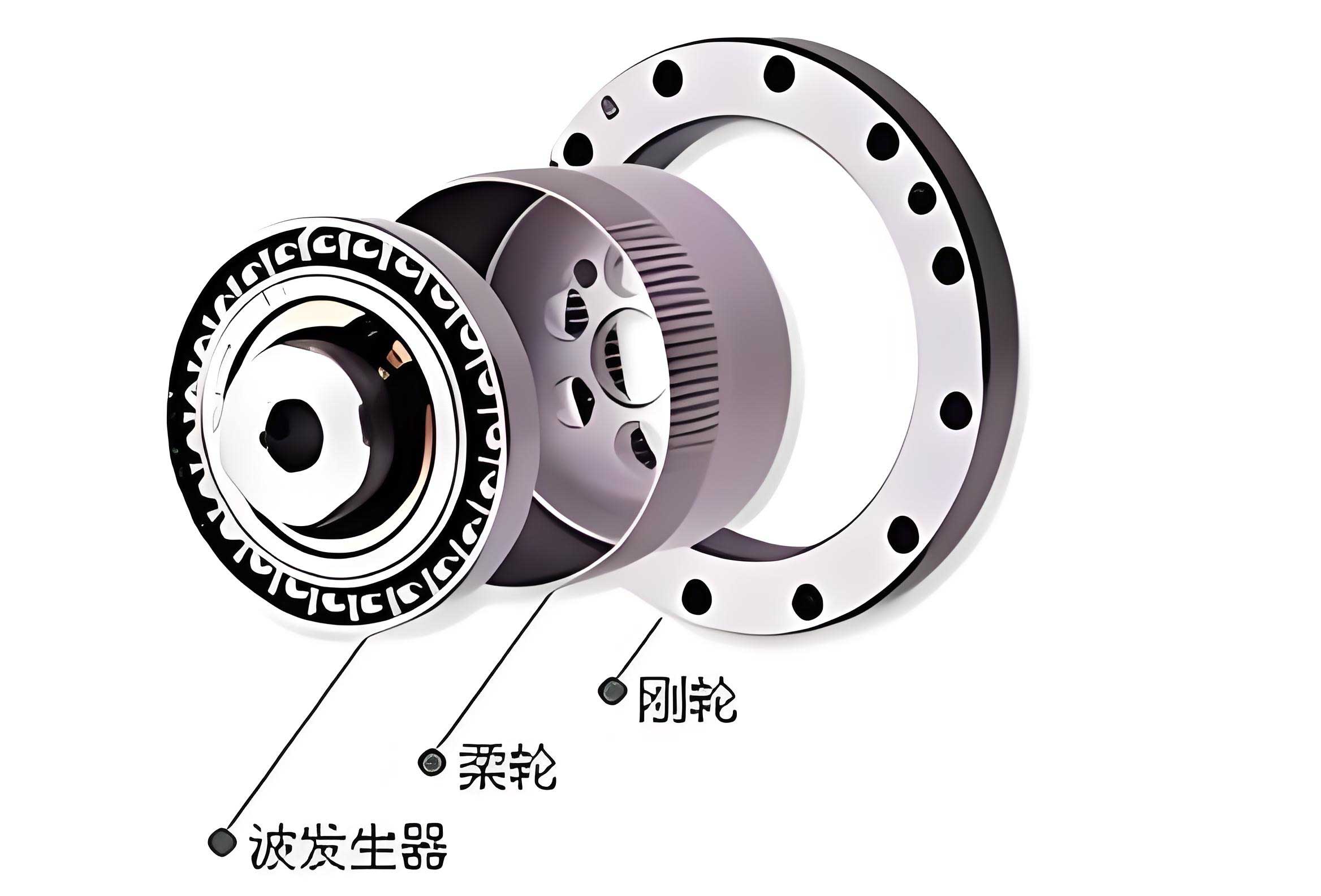
The fundamental architecture of an oscillating teeth end face strain wave gear comprises four primary components: the end face gear, the wave generator, the oscillating teeth (or活齿), and the槽轮 (often a carrier or slot wheel). In a single-sided transmission configuration, two key meshing pairs exist: Pair A between the wave generator and the rear end of the oscillating tooth, and Pair B between the end face gear and the front end of the oscillating tooth. In conventional symmetrical designs, both meshing pairs possess tooth profiles that are mirror images about their centerline, forming special Archimedean spiral surfaces. However, the asymmetrical tooth strain wave gear departs from this symmetry. Here, the tooth profiles on the wave generator, the oscillating teeth, and the end face gear are intentionally made asymmetrical. This design philosophy increases the arc length (and consequently the time) corresponding to the working engagement segment (the rise or lift phase) while decreasing the arc length for the non-working segment (the return or fall phase). This effectively implements a “slow-in, fast-out” motion cycle common in reciprocating mechanisms. The primary benefit is an increase in the number of teeth simultaneously engaged in the working phase, thereby distributing load more effectively and boosting the overall transmissible power of the strain wave gear system.
To quantitatively describe the degree of tooth asymmetry, I introduce the tooth profile asymmetry coefficient. This coefficient is fundamental for extending the engagement theory and surface equations from symmetrical to asymmetrical profiles, with the symmetrical case becoming a special subset. Let \(\lambda_W\) denote the asymmetry coefficient for the wave generator. It is defined as the ratio of the arc length on a cylinder of radius \(r\) corresponding to one working (lift) tooth surface of the wave generator’s face cam to the arc length corresponding to one complete wave on the same cylinder. Similarly, let \(\lambda_E\) be the asymmetry coefficient for the end face gear, defined as the ratio of the arc length on a cylinder of radius \(r\) corresponding to one working tooth surface of the gear to the arc length corresponding to one complete tooth on that cylinder. For a symmetrical profile, \(\lambda_W = \lambda_E = 0.5\).
Considering the circumferential development on a cylindrical surface of radius \(r\), when the lift and return face angles of the wave generator and oscillating tooth rear end are constants \(\theta_1\) and \(\theta_2\), and the corresponding tooth profile half-angles for the end face gear and oscillating tooth front end are constants \(\alpha_1\) and \(\alpha_2\), the following geometric relationships hold based on the development diagram:
$$
\tan \theta_1 = \frac{hU}{2\pi r \lambda_W}, \quad \tan \theta_2 = \frac{hU}{2\pi r (1 – \lambda_W)}
$$
$$
\tan \alpha_1 = \frac{2\pi r \lambda_E}{z_E h}, \quad \tan \alpha_2 = \frac{2\pi r (1 – \lambda_E)}{z_E h}
$$
where \(h\) is the theoretical lift of the wave generator face cam (equal to the theoretical tooth height of the end face gear) in mm, \(U\) is the number of waves on the generator (typically 2), and \(z_E\) is the number of teeth on the end face gear. From these, the ratios can be derived:
$$
\frac{\tan \theta_1}{\tan \theta_2} = \frac{1 – \lambda_W}{\lambda_W}, \quad \frac{\tan \alpha_1}{\tan \alpha_2} = \frac{\lambda_E}{1 – \lambda_E}
$$
The condition for correct meshing in an asymmetrical tooth strain wave gear is \(\lambda_W = \lambda_E\). Therefore, substituting this equality yields:
$$
\tan \theta_1 \tan \alpha_1 = \tan \theta_2 \tan \alpha_2
$$
For a strain wave gear to maintain a constant instantaneous transmission ratio across different radial positions, the product \(\tan \theta \tan \alpha\) must be constant. Extending this to the asymmetrical case, the condition for constant instantaneous transmission ratio becomes:
$$
\tan \theta_1 \tan \alpha_1 = \tan \theta_2 \tan \alpha_2 = \frac{U}{z_E} \quad \text{(constant)}
$$
This is a crucial design constraint. Once parameters \(h\), \(U\), \(z_E\), the large-end module \(m\), and \(\lambda_W\) (which equals \(\lambda_E\)) are chosen, the angles \(\theta_1, \alpha_1\) and \(\theta_2, \alpha_2\) can be calculated, defining the profile geometry of the asymmetrical strain wave gear.
The tooth surfaces in this strain wave gear are all special Archimedean spiral surfaces, where the generatrix is a straight line perpendicular to and intersecting the axis. The difference between symmetrical and asymmetrical profiles lies solely in the unequal angular extents of the working and non-working flanks. By incorporating the asymmetry coefficients, the surface equations for the symmetrical case can be generalized.
Mathematical Derivation of Tooth Surface Equations
I will now derive the tooth surface equations for each component in the asymmetrical tooth strain wave gear system. Coordinate systems are established for each part to facilitate the derivation.
1. Tooth Surface Equation of the Wave Generator Face Cam
For the wave generator (with wave number \(U=2\)), I establish a coordinate system \(O_1 – x_1y_1z_1\) fixed to the generator. The \(z_1\)-axis coincides with the generator’s axis of rotation. The \(x_1\)-axis is radial, and the \(y_1\)-axis completes the right-handed system. The tooth surface of the wave generator is a multi-start helical surface with \(U\) starts. Each start consists of a right-hand helical flank and a left-hand helical flank.
For the asymmetrical profile, the equations for the right-hand helical flank (working/lift surface) in the \(O_1 – x_1y_1z_1\) system are:
$$
\begin{cases}
x_1 = r \cos \varphi_W \\
y_1 = r \sin \varphi_W \\
z_1 = p_{W1} (\varphi_W – n \psi_W) \\
R_f \leq r \leq R_a
\end{cases}
$$
where \(n = 0, 1, 2, \dots, U-1\) and \(0 \leq \varphi_W – n \psi_W \leq \lambda_W \psi_W\).
The equations for the left-hand helical flank (non-working/return surface) are:
$$
\begin{cases}
x_1 = r \cos \varphi_W \\
y_1 = r \sin \varphi_W \\
z_1 = p_{W2} (n \psi_W – \varphi_W) \\
R_f \leq r \leq R_a
\end{cases}
$$
where \(n = 1, 2, \dots, U\) and \(0 \leq n \psi_W – \varphi_W \leq (1 – \lambda_W) \psi_W\).
In these equations:
– \(r\) is the radial coordinate (mm).
– \(R_f\) and \(R_a\) are the inner and outer radii of the wave generator face cam (mm).
– \(\varphi_W\) is the rotation angle of the wave generator (rad).
– \(\psi_W = 2\pi / U\) is the central angle corresponding to one wave (rad).
– \(p_{W1}\) and \(p_{W2}\) are the helical parameters for the right-hand and left-hand flanks, respectively, given by:
$$
p_{W1} = \frac{hU}{2\pi \lambda_W}, \quad p_{W2} = \frac{hU}{2\pi (1 – \lambda_W)}
$$
These parameters are directly related to the asymmetry coefficient \(\lambda_W\) and the lift angles. When \(\lambda_W = 0.5\) (symmetrical case), \(p_{W1} = p_{W2} = hU/\pi\), and the equations reduce to the standard symmetrical form, demonstrating that the symmetrical strain wave gear is a subset of this generalized model.
2. Tooth Surface Equation of the End Face Gear
For the end face gear (with tooth number \(z_E\)), I establish a coordinate system \(O_2 – x_2y_2z_2\) fixed to the gear, with the \(z_2\)-axis along its rotation axis. The end face gear’s tooth surface is a multi-start helical surface with \(z_E\) starts.
For the asymmetrical profile, the equations for the right-hand helical flank (working surface) in the \(O_2 – x_2y_2z_2\) system are:
$$
\begin{cases}
x_2 = r \cos \varphi_E \\
y_2 = r \sin \varphi_E \\
z_2 = p_{E1} (\varphi_E – n \psi_E) \\
R_f \leq r \leq R_a
\end{cases}
$$
where \(n = 0, 1, 2, \dots, z_E-1\) and \(0 \leq \varphi_E – n \psi_E \leq \lambda_E \psi_E\).
The equations for the left-hand helical flank (non-working surface) are:
$$
\begin{cases}
x_2 = r \cos \varphi_E \\
y_2 = r \sin \varphi_E \\
z_2 = p_{E2} (n \psi_E – \varphi_E) \\
R_f \leq r \leq R_a
\end{cases}
$$
where \(n = 1, 2, \dots, z_E\) and \(0 \leq n \psi_E – \varphi_E \leq (1 – \lambda_E) \psi_E\).
In these equations:
– \(r\), \(R_f\), and \(R_a\) have the same meanings and ranges as for the wave generator (ensuring conjugate action).
– \(\varphi_E\) is the rotation angle of the end face gear (rad).
– \(\psi_E = 2\pi / z_E\) is the central angle corresponding to one tooth (rad).
– \(p_{E1}\) and \(p_{E2}\) are the helical parameters:
$$
p_{E1} = \frac{h z_E}{2\pi \lambda_E}, \quad p_{E2} = \frac{h z_E}{2\pi (1 – \lambda_E)}
$$
Again, when \(\lambda_E = 0.5\), \(p_{E1} = p_{E2} = h z_E / \pi\), yielding the symmetrical case equations. The condition \(\lambda_W = \lambda_E\) ensures proper meshing between the wave generator and the end face gear via the oscillating teeth in this strain wave gear assembly.
3. Tooth Surface Equation of the Oscillating Teeth
The oscillating tooth has two ends: the rear end meshes with the wave generator (Pair A), and the front end meshes with the end face gear (Pair B). Separate coordinate systems are fixed to individual oscillating teeth. Let \(O_3 – x_3y_3z_3\) be attached to the rear end and \(O_4 – x_4y_4z_4\) to the front end. The asymmetry coefficient for the oscillating tooth is \(\lambda_O\), and for correct meshing, \(\lambda_O = \lambda_W = \lambda_E\).
For the rear end (meshing with wave generator), the right-hand helical flank surface equations in \(O_3 – x_3y_3z_3\) are:
$$
\begin{cases}
x_3 = r \cos \varphi_O \\
y_3 = r \sin \varphi_O \\
z_3 = p_{OW1} \varphi_O \\
R_f \leq r \leq R_a
\end{cases}
$$
where \(0 \leq \varphi_O \leq \lambda_O \psi_O\).
The left-hand helical flank equations are:
$$
\begin{cases}
x_3 = r \cos \varphi_O \\
y_3 = r \sin \varphi_O \\
z_3 = p_{OW2} (\psi_O – \varphi_O) \\
R_f \leq r \leq R_a
\end{cases}
$$
where \(0 \leq \psi_O – \varphi_O \leq (1 – \lambda_O) \psi_O\).
Here:
– \(\varphi_O\) is the rotation angle of the oscillating tooth, and it relates to the gear rotation; typically, \(\varphi_O = \varphi_E\) for kinematic consistency.
– \(\psi_O = 2\pi / z_E\) is the central angle corresponding to one oscillating tooth (same as \(\psi_E\)).
– The helical parameters are identical to those of the wave generator: \(p_{OW1} = p_{W1} = \frac{hU}{2\pi \lambda_O}\) and \(p_{OW2} = p_{W2} = \frac{hU}{2\pi (1 – \lambda_O)}\).
For the front end (meshing with end face gear), the right-hand helical flank surface equations in \(O_4 – x_4y_4z_4\) are:
$$
\begin{cases}
x_4 = r \cos \varphi_O \\
y_4 = r \sin \varphi_O \\
z_4 = -p_{OE1} \varphi_O \\
R_f \leq r \leq R_a
\end{cases}
$$
where \(0 \leq \varphi_O \leq \lambda_O \psi_O\).
The left-hand helical flank equations are:
$$
\begin{cases}
x_4 = r \cos \varphi_O \\
y_4 = r \sin \varphi_O \\
z_4 = -p_{OE2} (\psi_O – \varphi_O) \\
R_f \leq r \leq R_a
\end{cases}
$$
where \(0 \leq \psi_O – \varphi_O \leq (1 – \lambda_O) \psi_O\).
The helical parameters match those of the end face gear: \(p_{OE1} = p_{E1} = \frac{h z_E}{2\pi \lambda_O}\) and \(p_{OE2} = p_{E2} = \frac{h z_E}{2\pi (1 – \lambda_O)}\). The negative sign in the \(z_4\) coordinate accounts for the opposite direction of the helix relative to the rear end, ensuring conjugate motion with the end face gear in the strain wave gear transmission.
When \(\lambda_O = 0.5\), all helical parameters revert to their symmetrical forms, and the surfaces become standard Archimedean spirals with equal angular extents for both flanks.
Extended Analysis and Design Considerations
To fully appreciate the implications of these equations for the strain wave gear design, I will expand on several key aspects, including parameter selection, performance metrics, and comparative analysis with symmetrical profiles.
Parameter Interdependence and Design Tables
The design of an asymmetrical tooth strain wave gear involves a careful balance of parameters. The asymmetry coefficient \(\lambda\) (where \(\lambda = \lambda_W = \lambda_E = \lambda_O\)) is a primary design freedom. Its value influences the pressure angles, contact ratios, and stress distribution. Below is a table summarizing the effects of varying \(\lambda\) on key geometric parameters, assuming constant \(h\), \(U=2\), and \(z_E\).
| Parameter | Symbol | Expression | Trend as \(\lambda\) increases from 0.5 |
|---|---|---|---|
| Working flank lift angle | \(\theta_1\) | \(\tan \theta_1 = \frac{hU}{2\pi r \lambda}\) | Decreases |
| Non-working flank lift angle | \(\theta_2\) | \(\tan \theta_2 = \frac{hU}{2\pi r (1-\lambda)}\) | Increases |
| Working flank tooth angle | \(\alpha_1\) | \(\tan \alpha_1 = \frac{2\pi r \lambda}{z_E h}\) | Increases |
| Non-working flank tooth angle | \(\alpha_2\) | \(\tan \alpha_2 = \frac{2\pi r (1-\lambda)}{z_E h}\) | Decreases |
| Right-hand helical parameter (Wave Gen) | \(p_{W1}\) | \(p_{W1} = \frac{hU}{2\pi \lambda}\) | Decreases |
| Left-hand helical parameter (Wave Gen) | \(p_{W2}\) | \(p_{W2} = \frac{hU}{2\pi (1-\lambda)}\) | Increases |
| Arc length of working flank per wave/tooth | \(L_w\) | \(L_w = r \cdot \lambda \psi\) | Increases linearly with \(\lambda\) |
| Arc length of non-working flank per wave/tooth | \(L_n\) | \(L_n = r \cdot (1-\lambda) \psi\) | Decreases linearly with \(\lambda\) |
Where \(\psi\) represents \(\psi_W\) for the wave generator or \(\psi_E\) for the gear. The constant transmission ratio condition \(\tan \theta_1 \tan \alpha_1 = U/z_E\) imposes a constraint that must be satisfied regardless of \(\lambda\). This ensures kinematic correctness in the strain wave gear mechanism.
Kinematics and Transmission Ratio
The instantaneous transmission ratio \(i\) of a strain wave gear is given by the ratio of input to output angular velocities. For the oscillating teeth end face design, with the wave generator as input and the end face gear as output (or vice versa depending on configuration), the ratio is fundamentally determined by the tooth numbers. The derivation from the mesh conditions leads to the fixed ratio:
$$
i = \frac{\omega_{input}}{\omega_{output}} = \frac{z_E}{U}
$$
This holds true for both symmetrical and asymmetrical profiles, provided the constant product condition is met. The asymmetry does not alter the overall ratio but affects the distribution of motion within each cycle. The “slow-in, fast-out” characteristic means the output motion during the working flank engagement is more gradual, which can reduce acceleration shocks and improve dynamic performance in the strain wave gear system.
Contact Analysis and Load Distribution
Using the derived surface equations, one can perform contact analysis to determine the path of contact and pressure distribution. The condition for continuous contact between conjugate surfaces is that the common normal at the contact point passes through the instantaneous center of relative motion. For the asymmetrical strain wave gear, the contact lines on the tooth surfaces can be derived by solving the meshing equations simultaneously with the surface equations.
The meshing function for Pair A (wave generator and oscillating tooth rear end) can be expressed as:
$$
f_1(r, \varphi_W, \varphi_O) = 0
$$
And for Pair B (end face gear and oscillating tooth front end):
$$
f_2(r, \varphi_E, \varphi_O) = 0
$$
Given the kinematic constraints (\(\varphi_O\) linked to \(\varphi_E\) and \(\varphi_W\)), these functions ensure that the oscillating tooth properly transmits motion. The increased working flank arc length \(L_w\) due to \(\lambda > 0.5\) directly increases the potential contact ratio. The theoretical contact ratio \(m_c\) along the path of contact can be estimated as:
$$
m_c \approx \frac{L_w}{p_b}
$$
where \(p_b\) is the base pitch. A higher contact ratio in the strain wave gear leads to more teeth sharing the load, reducing stress on individual teeth and enhancing durability and power capacity.
Stress and Durability Considerations
The asymmetrical design influences the stress state within the strain wave gear components. The working flanks, with a smaller lift angle \(\theta_1\) (for \(\lambda > 0.5\)), experience a more favorable pressure angle, potentially reducing bending stresses. However, the non-working flanks have a steeper angle \(\theta_2\), but they are less loaded. Finite element analysis (FEA) using the exact surface equations is recommended for optimization. The helical parameters \(p\) affect the curvature of the surfaces, impacting contact Hertzian stresses. The general trend is that a larger \(\lambda\) makes the working flank more gradual (smaller \(p_{W1}, p_{E1}\)) and the non-working flank more abrupt (larger \(p_{W2}, p_{E2}\)). Designers must balance this to avoid undercutting on the non-working flank while maximizing the working flank engagement for the strain wave gear application.
Manufacturing Implications
Manufacturing the precise Archimedean spiral surfaces described by these equations requires advanced CNC machining or specialized grinding. The asymmetry adds complexity because the two flanks have different helical parameters. Tool path generation must account for the distinct \(p\) values and angular limits (\(\lambda \psi\) and \((1-\lambda)\psi\)). However, modern multi-axis machining makes this feasible. The payoff is a strain wave gear with superior performance characteristics. Quality control must verify that the actual manufactured surfaces adhere to the theoretical equations within tight tolerances to ensure smooth operation and high efficiency of the strain wave gear assembly.
Comparative Summary: Symmetrical vs. Asymmetrical Strain Wave Gear
To encapsulate the differences, I present a comparative table highlighting the key aspects of symmetrical and asymmetrical tooth profiles in oscillating teeth end face strain wave gears.
| Aspect | Symmetrical Profile (\(\lambda=0.5\)) | Asymmetrical Profile (\(\lambda > 0.5\)) |
|---|---|---|
| Tooth Profile Shape | Mirror-image flanks; equal angular extent for working and non-working segments. | Non-mirror flanks; working flank has larger angular extent than non-working flank. |
| Lift Angles | \(\theta_1 = \theta_2\), \(\alpha_1 = \alpha_2\) | \(\theta_1 < \theta_2\), \(\alpha_1 > \alpha_2\) (for \(\lambda>0.5\)) |
| Helical Parameters | \(p_{W1} = p_{W2} = hU/\pi\), \(p_{E1} = p_{E2} = h z_E/\pi\) | \(p_{W1} < p_{W2}\), \(p_{E1} < p_{E2}\) |
| Arc Length Distribution | Equal for both flanks: \(L_w = L_n = r \psi /2\) | Working flank longer: \(L_w = r \lambda \psi\), \(L_n = r (1-\lambda) \psi\) |
| Motion Cycle | Symmetrical rise and return. | “Slow-in, fast-out”: longer rise time, shorter return time. |
| Theoretical Contact Ratio | Lower, limited by half the wave/tooth arc. | Higher, can be increased by raising \(\lambda\). |
| Power Transmission Potential | Standard for given size. | Enhanced due to more teeth in contact during load-bearing phase. |
| Design Complexity | Lower; simpler equations and manufacturing. | Higher; requires careful selection of \(\lambda\) and asymmetric tool paths. |
| Kinematic Condition | \(\tan \theta \tan \alpha = U/z_E\) (constant) | \(\tan \theta_1 \tan \alpha_1 = \tan \theta_2 \tan \alpha_2 = U/z_E\) (constant) |
This comparison underscores that the asymmetrical tooth strain wave gear offers tangible benefits for high-power applications where maximizing the number of concurrently engaged teeth is critical.
Advanced Derivations and Model Validation
To further solidify the mathematical foundation, I can elaborate on the derivation of the constant transmission ratio condition from first principles. Consider the relative motion between the wave generator and an oscillating tooth. The oscillating tooth’s rear end surface is given by its equations in \(O_3\). The wave generator surface is given in \(O_1\). Using coordinate transformations and the condition of continuous tangency (shared normal vector), one can derive the meshing equation. This process, though lengthy, confirms that the condition \(\tan \theta_1 \tan \alpha_1 = U/z_E\) emerges naturally to ensure a constant velocity ratio, independent of the rotational position, in the strain wave gear.
Similarly, for Pair B, the meshing between the oscillating tooth front end and the end face gear yields the same constant product condition. The consistency across both pairs is what guarantees the overall constant transmission ratio of the strain wave gear assembly. Computational simulation, such as generating tooth contact patterns using the surface equations, can validate the model. By discretizing the surfaces and calculating minimum distances under loaded conditions, engineers can predict the contact ellipse dimensions and locations, ensuring that the asymmetrical design does not lead to edge contact or excessive stress concentrations in the strain wave gear.
Conclusion
In this extensive treatment, I have detailed the structure, design parameters, and mathematical modeling of asymmetrical tooth profiles in oscillating teeth end face strain wave gears. By introducing the tooth profile asymmetry coefficient \(\lambda\), I generalized the engagement theory and surface equations from the symmetrical case. The key condition for maintaining a constant instantaneous transmission ratio is \(\tan \theta_1 \tan \alpha_1 = \tan \theta_2 \tan \alpha_2 = U/z_E\), which dictates the geometry of the working and non-working flanks. The tooth surface equations for the wave generator, end face gear, and both ends of the oscillating teeth have been derived in their full asymmetrical form, incorporating the helical parameters \(p_{W1}, p_{W2}, p_{E1}, p_{E2}\) that depend on \(\lambda\). When \(\lambda = 0.5\), these equations seamlessly reduce to the symmetrical case, demonstrating the generality of the model.
The asymmetrical design offers a significant advantage for power-intensive applications by increasing the arc length of the working engagement segment, thereby allowing more teeth to share the load simultaneously. This enhances the torque capacity and operational smoothness of the strain wave gear. The derived equations provide a precise mathematical foundation for designing, analyzing, and manufacturing these advanced strain wave gear systems. Future work could involve optimizing the asymmetry coefficient \(\lambda\) for specific load cases, exploring non-constant asymmetry along the tooth depth, or integrating these models into digital twin simulations for predictive maintenance of strain wave gear drives in robotic and industrial applications. The strain wave gear, in its asymmetrical incarnation, represents a sophisticated evolution in precision gearing technology, pushing the boundaries of power density and performance.