
The strain wave gear, commonly known as a harmonic drive, represents a fascinating and highly efficient type of gearing mechanism. Its unique operating principle, based on controlled elastic deformation, sets it apart from conventional gear systems. In this discussion, I will elaborate on the fundamental composition, working principle, and the intricate design philosophy behind its core flexible component, drawing from extensive design experience. The term ‘strain wave gear’ perfectly encapsulates the essence of this technology—the generation and propagation of a controlled strain wave within a flexible member to produce motion.
The strain wave gear assembly is remarkably simple in its basic construction, consisting of only three primary elements: the Flexspline, the Circular Spline, and the Wave Generator.
- Flexspline: This is a thin-walled, flexible external gear. Its inner diameter typically mates with the outer ring of a flexible bearing, and it is usually attached to the output side of the gear unit.
- Circular Spline: This is a rigid, ring-shaped internal gear, generally fixed to the gear housing. A key design feature is that it possesses two more teeth than the Flexspline.
- Wave Generator: This assembly serves as the input. It usually comprises an elliptical cam and a specially designed flexible bearing. The bearing’s inner ring is fixed to the cam, forcing its outer ring (and consequently the Flexspline) into an elliptical shape.
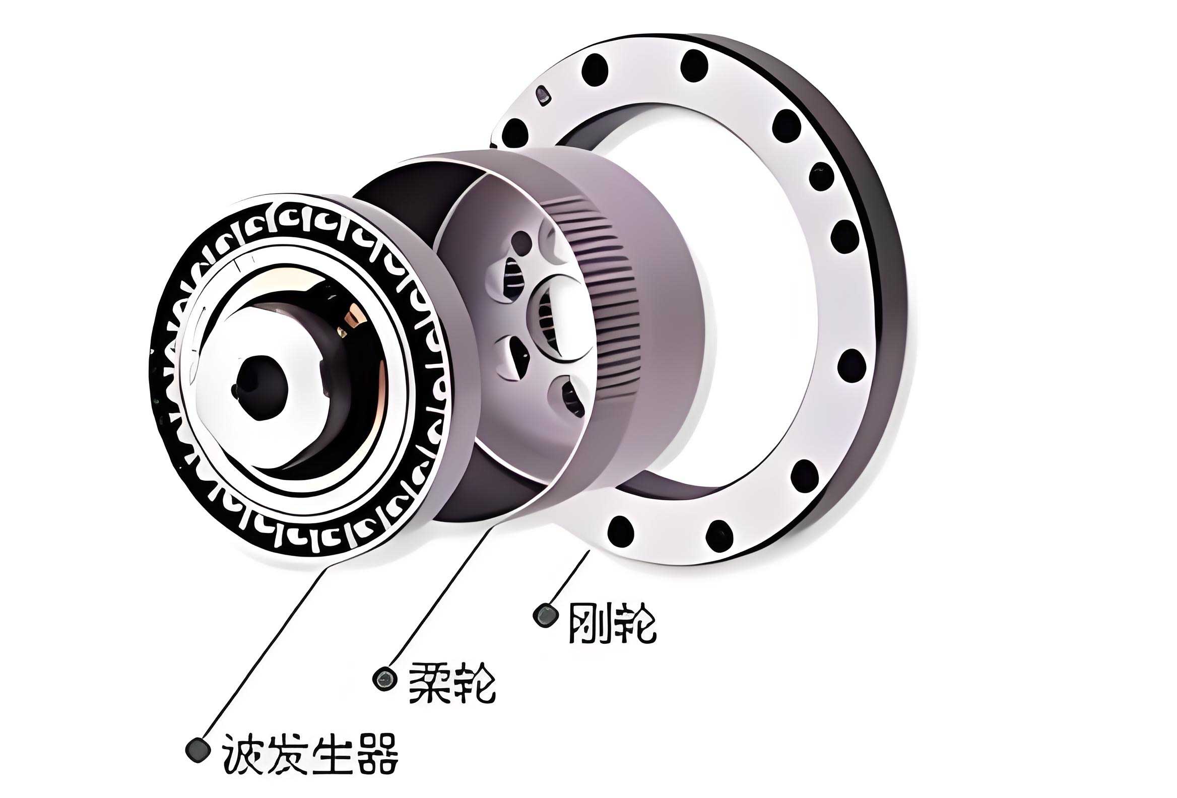
The fundamental operation of a strain wave gear is based on meshing through elastic deformation. During operation, the Wave Generator deforms the Flexspline into an elliptical shape. At the major axis of the ellipse, the teeth of the Flexspline fully engage with the tooth spaces of the Circular Spline. At the minor axis, the teeth are completely disengaged. The regions between these points are in a state of either meshing-in or meshing-out. As the Wave Generator rotates continuously, the elliptical strain wave propagates through the Flexspline. This forces the gear teeth to cyclically engage and disengage. Because the Circular Spline has more teeth than the Flexspline, a relative motion occurs. For each complete revolution of the Wave Generator, the Flexspline rotates backward (relative to the Wave Generator’s direction) by an amount corresponding to the difference in tooth count—typically two teeth. This “differential motion” is the source of the high reduction ratio. The process, often termed “tooth differential” or “error motion,” is the core of the strain wave gear principle.
The unique architecture of the strain wave gear confers a set of exceptional characteristics that make it superior to conventional gearboxes in many high-performance applications.
| Characteristic | Description | Typical Range/Note |
|---|---|---|
| High Reduction Ratio | Single-stage units offer very high ratios. Compound designs can achieve extreme ratios. | Single-stage: 50–500 (up to 4,000 with special designs). Compound: up to 107. |
| High Torque Capacity | Multiple tooth pairs are in simultaneous contact, distributing the load. | ~30–40% of total teeth share the load under nominal torque. |
| High Precision & Zero Backlash | Elastic preload and multi-tooth contact allow for minimal, adjustable, or zero kinematic backlash. | Accuracy is typically one grade higher than conventional gears of similar manufacturing quality. |
| High Efficiency | Despite the elastic deformation, rolling motion and optimized tooth profiles yield good efficiency. | Single-stage efficiency: 65% – 90%, depending on ratio and load. |
| Compactness & Light Weight | High ratio in a single stage leads to a very power-dense design. | Volume and mass can be 1/3 to 1/2 of equivalent conventional gearboxes. |
| Smooth Operation | Controlled elastic interaction results in quiet, vibration-free operation with minimal cogging. | Superior for high-servo performance applications. |
These advantages have led to the widespread adoption of strain wave gear systems across demanding fields. They are ubiquitous in aerospace, robotics (especially for joint actuators), precision machine tools, semiconductor manufacturing equipment, medical devices, optical systems, and many forms of industrial automation. The compact, high-torque, and zero-backlash nature of the strain wave gear makes it virtually indispensable in modern high-performance servo systems.
The heart of any strain wave gear is the Flexspline. It operates under a state of continuous, controlled cyclic elastic deformation. Its thin-walled, flexible metal structure directly dictates the overall performance of the gear unit, including its torsional stiffness, positioning accuracy, fatigue life, and torque capacity. The Flexspline design is therefore paramount. Common configurations include the cup type and the hat (or “top-hat”) type, both featuring a thin-walled external gear rim. We will focus our design discussion on the more common cup-type Flexspline. The following sections detail the critical aspects of its design: the diaphragm, the cup barrel, the tooth profile, and the tooth alignment.
Diaphragm and Barrel Design
The Flexspline absorbs the cyclical deformation imposed by the Wave Generator primarily through its diaphragm and the adjacent barrel section. These areas must be meticulously designed to manage stress, control the deformation wave, and ensure infinite fatigue life.
Diaphragm Design
The diaphragm is the transition region connecting the rigid output hub to the flexible barrel. Its profile is typically constructed from a series of tangential arcs to ensure a smooth stress flow and avoid dangerous stress concentrations. A common approach uses four consecutive arcs.
Let us define the primary design parameters. Let \( D \) be the pitch diameter of the Flexspline. The thickness at the diaphragm root, denoted \( t_a \), is fundamental. It is bounded by empirical rules related to the pitch diameter:
$$ 0.01D \le t_a \le 0.025D $$
The thickness tapers from this root value towards the barrel. A key ratio is the thickness at the diaphragm’s end (where it meets the major blend radius) to the root thickness, which should be constrained to manage bending stress:
$$ \frac{t_b}{t_a} \le \frac{1}{3} $$
The geometry of the arcs is defined by their radii \( R_1, R_2, R_3 \) (often expressed as ratios relative to a base radius) and their respective central angles \( \alpha_1, \alpha_2, \alpha_3 \). The centers of these arcs, \( O_1, O_2, O_3, O_4 \), are offset to create the smooth, tapering contour. The design goal is to maintain a continuous first derivative (slope) along the profile to minimize peak stresses.
Barrel Design
The barrel is the cylindrical section that hosts the external teeth. Its length and thickness profile are critical for proper engagement and stress distribution. The barrel length can be considered in two parts: a tapered section \( L_3 \) and a parallel section \( L_4 \) of constant thickness \( t_d \).
The tapered section \( L_3 \) is often an arc (with center \( O_7 \)) that transitions from the diaphragm end thickness \( t_b \) to the nominal barrel wall thickness \( t_c \). The ratio of the arc radius to a reference radius is a design variable \( R_4 \). The minimum thickness \( t_c \) is related to the parallel section thickness by a factor \( N \):
$$ \frac{t_c}{t_d} = N $$
where \( N \) is typically less than 1 (e.g., \( N \approx 0.7 – 0.9 \)), allowing the tooth root region to be slightly thicker for strength while the non-toothed region can be thinner to aid flexibility.
Transition Blending
The junction between the diaphragm and the barrel is a critical stress area. It is smoothed using large blend radii. Defining these radii relative to a base radius from the diaphragm design, we have internal and external blend radii characterized by a ratio \( M \):
$$ R_{blend\_int} = M \cdot R_{base}, \quad R_{blend\_ext} = (M + k) \cdot R_{base} $$
where \( k \) is a small offset factor. A large \( M \) (e.g., >5) is desirable to reduce stress concentration factors significantly. This is a crucial zone where Finite Element Analysis (FEA) is essential for validation.
Tooth Profile Design
The tooth profile in a strain wave gear is arguably its most defining performance feature. The evolution from simple triangular teeth to modern sophisticated profiles has driven major leaps in the capacity and precision of strain wave gears.
First, the basic kinematic parameters must be defined. For a standard configuration, given the reduction ratio \( R \), the number of teeth on the Flexspline \( Z_f \) and the Circular Spline \( Z_c \) are:
$$ Z_f = 2R $$
$$ Z_c = Z_f + 2 $$
This two-tooth difference is standard for the simplest, most common wave generator profile.
The history of tooth profiles illustrates a quest for better performance:
| Profile Type | Characteristics | Advantages & Limitations |
|---|---|---|
| Involute | Standard gear profile. Simple to manufacture. | Prone to interference under large deflection; limited contact area; higher wear. |
| Double-Arc (S-Type) | Two circular arcs form convex and concave flanks. | Superior load distribution, reduced stress, higher torque capacity than involute. |
| IH (Involute-Hooke) Profile | Patented profile based on conjugate action theory. | Excellent kinematic accuracy, very high torsional stiffness, optimized for precision robotics. |
In our development work, we have pursued novel profile geometries, which we can refer to as an Enhanced-Stress (ES) profile philosophy. The core design objective is to maximize the conjugate action—the theoretical condition where the tooth surfaces transmit motion with a constant angular velocity ratio while maintaining continuous contact—under the specific elastic deformation of the Flexspline. This involves solving the complex geometry of the deformed Flexspline neutral line and generating a tooth flank for the Circular Spline that is perfectly conjugate to the moving Flexspline tooth. The resulting profile often deviates significantly from standard arcs or involutes and is optimized for factors like:
- Contact Stress Minimization: Shaping the profile to enlarge the contact ellipse and lower Hertzian contact stresses, governed by:
$$ \sigma_H = \sqrt{\frac{F_n}{\pi L} \cdot \frac{\frac{1}{\rho_1} \pm \frac{1}{\rho_2}}{\frac{1-\nu_1^2}{E_1} + \frac{1-\nu_2^2}{E_2}}} $$
where \( F_n \) is the normal load, \( L \) is the face width, \( \rho \) are radii of curvature, \( E \) is Young’s modulus, and \( \nu \) is Poisson’s ratio. - Sliding Velocity Reduction: Minimizing relative sliding between tooth flanks to improve efficiency and reduce wear.
- Interference Prevention: Ensuring the profile avoids gouging during the meshing-in and meshing-out phases across the full operational deflection range.
Tooth Alignment (Lead Crowning)
A critical, often overlooked aspect of Flexspline design is the alignment of teeth along the face width, known as the tooth lead. Due to the conical deformation of the cup (the “cup opening angle” or “coning effect”), the radial deflection of the Flexspline’s neutral line is not constant along its axis. The deflection is typically greatest at the open end near the teeth and reduces towards the closed diaphragm end. If the teeth were cut perfectly straight and parallel, this variation in deflection would cause end-loading (contact only at one edge of the tooth face) or even edge interference at the ends of the gear rim.
To compensate for this and achieve a uniform contact pattern across the full face width, the teeth are given a slight lead crown or helix angle. The theoretical value for this corrective angle \( \alpha \) can be derived from the geometry of deformation. If \( \omega_0 \) is the radial deflection at the open end of the cup (where the teeth are located) and \( L_c \) is the axial distance from the diaphragm’s effective pivot point (often near the cup’s closed end) to the tooth center, then the nominal crown angle is:
$$ \alpha = \arctan\left(\frac{\omega_0}{L_c}\right) $$
In practice, \( \alpha \) is a small angle, typically in the range of 10 to 60 arc-minutes. However, the actual applied crown is not a simple linear twist. It is often a sophisticated, non-linear profile (e.g., a parabolic or sinusoidal modification) optimized via loaded tooth contact analysis (LTCA) to ensure that under the designated operating torque, the contact pressure is evenly distributed from one end of the tooth to the other. This crowning is essential for maximizing the load-carrying capacity, minimizing stress concentrations, and ensuring smooth, predictable behavior of the strain wave gear under load.
Conclusion
The design of a high-performance strain wave gear is a deeply interdisciplinary exercise, blending classical gear theory, elasticity, fatigue analysis, and advanced manufacturing. We have explored the fundamental principles that make the strain wave gear unique and delved into the detailed design rationale for its core flexible component, the Flexspline. The diaphragm and barrel must be shaped to safely manage cyclical stresses, the tooth profile must be optimized for conjugate motion and load sharing under deformation, and the tooth alignment must be corrected to account for the non-uniform deflection of the cup structure. Each of these elements—diaphragm, barrel, profile, and lead—plays a vital role in determining the overall performance metrics: torsional stiffness, positional accuracy, lifetime, torque capacity, and efficiency. Mastering the interplay of these design factors is key to advancing the state-of-the-art in strain wave gear technology, enabling its continued adoption in ever more precise and demanding mechanical systems. The relentless pursuit of optimization in these areas ensures that the strain wave gear remains a cornerstone of precision motion control.