
In the realm of Heating, Ventilation, and Air Conditioning (HVAC) automation, damper actuators are critical components responsible for precisely regulating airflow by adjusting valve openings. Traditionally, these actuators employ multi-stage spur gear trains to achieve the necessary high torque amplification from a small electric motor. While functional, this conventional approach suffers from a high part count, increased assembly complexity, and consequently, higher manufacturing costs. This design study explores a novel, more integrated solution: the application of strain wave gearing. Also known as harmonic drive, strain wave gearing offers exceptional advantages for this application, including very high single-stage reduction ratios, compactness, high positional accuracy, low backlash, and smooth, quiet operation. This article details the comprehensive design process, from schematic selection and parametric calculation to kinematic simulation and finite element static analysis, for a damper actuator utilizing a compact strain wave gear assembly.
1. Introduction and Design Rationale
The primary function of a damper actuator is to convert the high-speed, low-torque rotary motion of an electric motor into a low-speed, high-torque output suitable for positioning a valve damper. A typical commercial damper actuator, as analyzed, uses a multi-stage plastic spur gear train. The kinematic chain of such a system is often complex, requiring numerous small, precision-molded gears. This not only increases the bill of materials and assembly time but also accumulates errors and backlash across multiple stages.
Strain wave gearing presents an elegant alternative. Its operation relies on the elastic deformation of a flexible splined component (the flexspline) by an elliptical wave generator, causing it to mesh with a rigid circular spline (the circular spline). The difference in tooth count between the flexspline and circular spline creates a high reduction ratio in a single, coaxial stage. For a damper actuator, this translates to a drastic simplification of the drive train, potential for a more compact and robust housing, and improved performance metrics like responsiveness and accuracy.
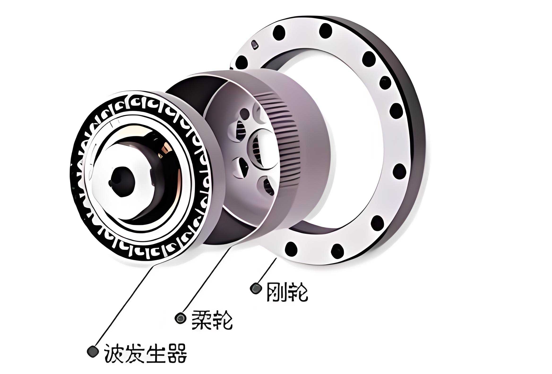
The target performance parameters for this redesign are derived from an existing commercial unit, as summarized in Table 1.
| Parameter | Value |
|---|---|
| Input Speed, \(n_{in}\) | 1191 rpm |
| Total Transmission Ratio, \(i_{total}\) | > 7,000 |
| Required Output Torque, \(T_{out}\) | 15 N·m |
| Maximum Physical Envelope | 134 mm × 66 mm × 62 mm |
| Output Rotation (Stroke) | 95° |
Achieving a ratio exceeding 7,000:1 with a single strain wave gear stage is impractical. Therefore, a compound configuration is necessary. The design process follows a structured methodology: selection of a compound strain wave gear scheme, detailed component design and material selection, kinematic verification via simulation, and structural validation through static finite element analysis.
2. Transmission Scheme and Component Design
2.1 Selection of Compound Strain Wave Gear Scheme
For ultra-high reduction ratios, compound strain wave gear configurations are employed. Three primary schemes were evaluated for integration into the damper actuator:
- Scheme A (Cascaded): The flexspline of the first stage drives the wave generator of the second. The second-stage flexspline is fixed, and the two circular splines are coupled to the output. This scheme tends to have a large radial footprint.
- Scheme B (Differential): The circular spline of the first stage drives the wave generator of the second. The second-stage circular spline is fixed, and the two flexsplines are coupled to the output. This scheme generally results in a larger axial length.
- Scheme C (Common Wave Generator): A single, dual-profile wave generator acts on a single flexspline with two different external tooth profiles. The first corresponding circular spline is fixed, and the second circular spline serves as the output. This scheme offers the most balanced and compact volume, though its theoretical efficiency is slightly lower.
Given the space-constrained environment of a damper actuator and its intermittent duty cycle (where peak efficiency is less critical than compactness), Scheme C was selected. Its coaxial, nested design optimally utilizes the available volume. The final drive train, shown schematically below, combines this compound strain wave gear with a final bevel gear stage to provide the required 90° output shaft orientation.
Kinematic Principle: The motor drives the elliptical wave generator. This generator causes the dual-tooth-profile flexspline to deform. The first set of teeth on the flexspline meshes with the fixed circular spline (CS1). Because CS1 has \(Z_{CS1}\) teeth and the matching flexspline segment has \(Z_{F1}\) teeth (where \(Z_{CS1} – Z_{F1} = \pm 2\)), the deformation induces a slow rotation of the flexspline body relative to the wave generator. This rotation is then transferred to the second meshing pair. The second segment of the flexspline (with \(Z_{F2}\) teeth) meshes with the output circular spline (CS2, with \(Z_{CS2}\) teeth). The relative motion between the already rotating flexspline and CS2 results in a further reduced output speed at CS2. The total reduction ratio \(i_{SWG}\) for this common-wave-generator compound system is given by:
$$ i_{SWG} = \frac{Z_{F1} \times Z_{CS2}}{(Z_{CS1} – Z_{F1}) \times (Z_{CS2} – Z_{F2})} $$
The output from CS2 is then transmitted via a shaft to a bevel gear pair, providing the final direction change and a moderate additional ratio. The total system ratio is the product \(i_{total} = i_{SWG} \times i_{bevel}\).
2.2 Parameter Determination and Geometric Design
Based on the target ratio and envelope constraints, key geometric parameters for the strain wave gear were calculated following standard harmonic drive design procedures. The module, tooth counts, and profile shift coefficients were iteratively determined to ensure proper meshing, sufficient strength, and to avoid interference. The critical parameters are listed in Table 2.
| Component | Parameter | Symbol | Value |
|---|---|---|---|
| Strain Wave Gear | Module | \(m\) | 0.3 mm |
| Flexspline Profile 1 Tooth Count | \(Z_{F1}\) | 168 | |
| Circular Spline 1 (Fixed) Tooth Count | \(Z_{CS1}\) | 170 | |
| Flexspline Profile 2 Tooth Count | \(Z_{F2}\) | 170 | |
| Circular Spline 2 (Output) Tooth Count | \(Z_{CS2}\) | 172 | |
| Wave Generator Major Axis | \(a\) | 15.44 mm | |
| Wave Generator Minor Axis | \(b\) | 14.84 mm | |
| Bevel Gear Stage | Module | \(m_{bevel}\) | 1.0 mm |
| Pinion/Output Gear Teeth | \(Z_p / Z_g\) | 16 / 32 |
The elliptical profile of the wave generator, which deforms the flexspline, is defined in polar coordinates \((\rho, \phi)\) by the equation:
$$ \rho(\phi) = \frac{a \cdot b}{\sqrt{(b \cdot \cos \phi)^2 + (a \cdot \sin \phi)^2}} $$
where \(a\) and \(b\) are the major and minor semi-axes, respectively. A cam follower-type generator with a thin-walled deep-groove ball bearing was chosen for its simplicity and effectiveness.
2.3 Material Selection and Strength Verification
Material choice is paramount for strain wave gear components. The flexspline undergoes continuous cyclic elastic deformation, demanding high fatigue strength, good toughness, and consistent elastic properties. Traditionally, alloy steels are used, but they add cost and manufacturing complexity. For a cost-sensitive application like a damper actuator, engineering plastics offer a compelling alternative, enabling injection molding for complex parts and significant cost reduction.
After evaluating properties, Nylon 1010 was selected for the flexspline and the bearing races of the wave generator due to its excellent fatigue endurance, good elasticity, and low moisture absorption. The rigid components—the circular splines, housing, and bevel gears—were specified from Polyoxymethylene (POM), known for its high strength, stiffness, low friction, and dimensional stability. Key properties are in Table 3.
| Material | Elastic Modulus (GPa) | Tensile Strength (MPa) | Fatigue Strength (MPa) |
|---|---|---|---|
| Nylon 1010 | 1.6 | 55 | 24 |
| POM | 2.9 | 70 | 35 |
The primary failure modes for a plastic strain wave gear are tooth surface wear and flexspline fatigue fracture. Verification calculations were performed:
1. Tooth Surface Pressure (Wear): The contact pressure \(p\) on the tooth flank must be below the allowable pressure \([p]\) for the material pair. The calculated pressure was found using:
$$ p = \frac{K \cdot T_1}{\phi_d \cdot d_1 \cdot h_n \cdot Z_v} $$
where \(K\) is the application factor, \(T_1\) is the torque on the flexspline, \(\phi_d\) is the face width coefficient, \(d_1\) is the flexspline pitch diameter, \(h_n\) is the working tooth height, and \(Z_v\) is the number of simultaneously engaged teeth. The calculation yielded \(p \approx 8.1 \, \text{MPa}\), which is at the safe limit for Nylon-POM interaction under intermittent duty.
2. Flexspline Fatigue Strength: The flexspline is subjected to alternating bending stresses. The safety factor \(S\) against fatigue failure was calculated based on the Goodman criterion for combined stress:
$$ \frac{1}{S} = \frac{\sigma_a}{S_{\sigma} \cdot \sigma_{-1}} + \frac{\tau_m}{S_{\tau} \cdot \tau_{-1}} $$
Here, \(\sigma_a\) and \(\tau_m\) are the stress amplitude and mean shear stress, respectively, \(\sigma_{-1}\) and \(\tau_{-1}\) are the material’s fatigue limits, and \(S_{\sigma}\), \(S_{\tau}\) are stress concentration factors. The calculated composite safety factor was \(S \approx 2.8\), significantly greater than the minimum required value of 1.5, confirming the flexspline’s structural integrity.
3. Kinematic Simulation of the Assembly
To validate the kinematic design and ensure correct motion transfer, a multi-body dynamics model was created. The detailed 3D assembly, modeled in SolidWorks, was imported into ADAMS/View. Materials were assigned, and appropriate joints and constraints were applied: fixed joints for stationary parts, revolute joints for rotations, and coupler joints to enforce the kinematic relationships between the strain wave gear components (e.g., the motion ratio between the wave generator rotation and the forced flexspline rotation). A rotational motion driver with a step function was applied to the input shaft to simulate the motor’s startup: \( \text{STEP}(time, 0, 0, 0.1, 7146) \, \text{deg/s} \) (equivalent to 1191 RPM). A constant load torque of 15 N·m was applied to the final output bevel gear.
The simulation results successfully demonstrated the correct kinematic behavior. The direction of rotation reversed between the wave generator and the flexspline, as expected from the meshing with the fixed circular spline. The final output rotated in the intended direction. Most importantly, the simulated speed ratio between the input (wave generator) and the final output was measured to be approximately 14,448:1. This exceeds the original requirement of >7,000:1 and validates the theoretical ratio calculation for the compound strain wave gear and bevel gear combination. The motion was smooth without indication of binding or discontinuity, confirming the soundness of the geometric design and assembly constraints.
4. Static Structural Analysis via Finite Element Method
While kinematic simulation verifies motion, static structural analysis is essential to ensure components can withstand the operational loads without excessive deformation or failure. A finite element analysis (FEA) was conducted on the core transmission assembly (wave generator, flexspline, circular splines, and bevel gears) using ANSYS Static Structural.
4.1 Model Preparation and Boundary Conditions
The geometry was simplified by merging the wave generator cam and bearing into a single deformable body. Materials (Nylon 1010 and POM) were assigned with their non-linear properties approximated. A high-fidelity mesh was generated, particularly refining the regions around tooth contacts. The critical step was defining the contact pairs:
- Flexspline inner surface to Wave Generator outer surface (Frictional).
- Tooth flanks between Flexspline Profile 1 and Fixed Circular Spline (Frictional).
- Tooth flanks between Flexspline Profile 2 and Output Circular Spline (Frictional).
- Tooth flanks between the Bevel Gears (Frictional).
Boundary conditions were applied to represent the worst-case static loading scenario: The fixed circular spline and housing were fully constrained. The flexspline was prevented from axial movement. A cylindrical support was applied to the output shaft, allowing only rotation. A static torque of \(T_{load} = 45 \, \text{N·m}\) (three times the rated torque for a safety margin) was applied to the output bevel gear hub.
4.2 Analysis Results and Discussion
The solved model provided insights into stress distribution and deformation. The key results are summarized in Table 4.
| Result Metric | Maximum Value | Location |
|---|---|---|
| Total Deformation | 0.0235 mm | Output Bevel Gear Teeth |
| Equivalent (von-Mises) Stress | 11.52 MPa | Root of Output Bevel Gear Teeth |
| Maximum Principal Stress | 14.68 MPa | Contact region on Bevel Gear Teeth |
Interpretation:
The maximum deformation is negligible (0.0235 mm), indicating high overall stiffness. The maximum stresses are concentrated in the bevel gear teeth, not in the strain wave gear components. This is because the 45 N·m load is directly reacted by the final bevel gear pair. The peak von-Mises stress of 11.52 MPa is below the yield strength of POM (~70 MPa) and very close to, but still below, its fatigue endurance limit (approx. 11.67 MPa for this load case), suggesting the bevel gear is the limiting component under this extreme overload. Crucially, the stresses within the Nylon 1010 flexspline, particularly in its critical cup wall and tooth root regions, were significantly lower, with maximum values around 6-8 MPa, well within its safe fatigue range. This confirms that the strain wave gear design is robust and that the assembly can safely handle loads substantially higher than the specified 15 N·m requirement.
5. Conclusion
This design study successfully developed a novel drive structure for a damper actuator based on compound strain wave gearing. The proposed design replaces a complex multi-stage spur gear train with a single, integrated coaxial assembly, offering a path toward reduced part count, simpler assembly, and a more compact form factor. The common wave generator compound scheme (Scheme C) was identified as optimal for this space-constrained application. Detailed design of the strain wave gear components was performed, selecting engineering plastics (Nylon 1010 and POM) to enable cost-effective manufacturing. Strength calculations confirmed the flexspline’s safety against fatigue and wear under specified loads.
Kinematic simulation in ADAMS validated the theoretical high-ratio motion transmission and correct directional relationships within the assembly. Finally, a static finite element analysis demonstrated the structural integrity of the design under an overload condition, revealing that the overall deformation is minimal and that the critical stresses are within the safe limits of the chosen materials, with the final bevel gear stage being the performance bottleneck under extreme torque.
In summary, the strain wave gear-based damper actuator design is not only feasible but also offers distinct advantages over conventional designs. It meets and exceeds the target performance specifications for torque, ratio, and size, providing a reliable and efficient solution for precision airflow control in HVAC systems. The successful virtual prototyping through simulation and FEA provides a strong foundation for subsequent physical prototyping and product development.