
In the realm of industrial power transmission, particularly within the demanding environments of pulp and paper manufacturing machinery, the cycloidal drive stands out for its exceptional torque density, high reduction ratios, and robust overload capacity. My extensive experience in equipment maintenance and component machining has repeatedly highlighted the critical role of a single, often overlooked component within this cycloidal drive system: the eccentric bearing sleeve, or when configured for specific performance, the double eccentric sleeve. The precision of this component is not merely a matter of dimensional accuracy; it is the linchpin for the entire reducer’s smooth operation, longevity, and reliability. A poorly manufactured sleeve leads directly to premature bearing failure, abnormal meshing of the cycloidal disc, severe vibration, and ultimately, unplanned production stoppages. This article, drawn from practical engineering challenges, details the design rationale and implementation of specialized processing tooling developed to manufacture a high-precision 180° double eccentric bearing sleeve, thereby elevating the performance and service life of the cycloidal drive.
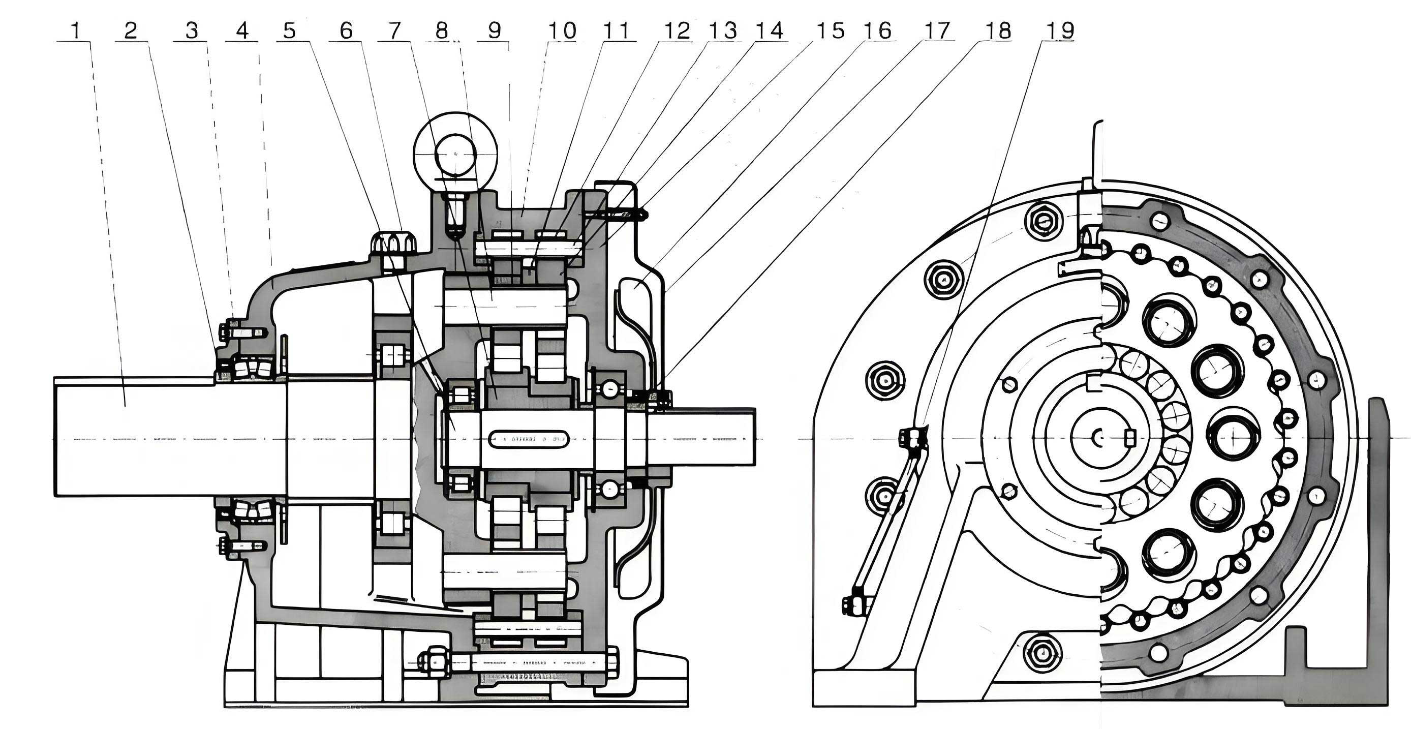
The operational heart of a cycloidal drive is a fascinating principle of motion conversion. An input shaft, fitted with an eccentric cam or sleeve, causes a cycloidal disc to undergo a compound eccentric motion. This disc, with its lobed profile, meshes with a stationary ring of pin gears (needle rollers housed in a shell). For each full rotation of the input shaft, the cycloidal disc wobbles, causing it to rotate slightly in the opposite direction due to its engagement with the pins. This slow reverse rotation is then output through a mechanism of pins and holes or a wobble plate. The eccentricity, denoted as $e$, is the fundamental parameter governing this motion. The relationship between input speed ($n_{in}$), the number of lobes on the cycloid disc ($N_c$), the number of pin gears ($N_p$), and the output speed ($n_{out}$) is given by the standard reduction ratio formula for a single-stage cycloidal drive:
$$ i = \frac{n_{in}}{n_{out}} = -\frac{N_p}{N_p – N_c} $$
The magnitude of the eccentricity $e$ is precisely calculated to ensure proper clearance and rolling contact between the cycloid disc lobe and the pin gears. It is a small dimension, typically in the range of a few millimeters, but its accuracy is paramount.
In many standard cycloidal drive designs, a single eccentric sleeve is used. However, configurations requiring higher load capacity or specific compact layouts may employ a dual-disc design with two cycloidal discs phased 180° apart to balance inertial forces. This necessitates a bearing sleeve with two eccentric outer diameters, also phased 180° apart, on a common bore. This is the 180° double eccentric bearing sleeve. Its geometry imposes severe machining challenges: the two outer diameters (where bearings are pressed on) must be precisely positioned relative to the common inner bore, with their axes parallel but offset by the specified eccentricity $e$ in exactly opposite directions. The tolerances for these features are extremely tight. The bearing journals typically require a k6 tolerance for a tight interference fit with the bearing inner race, while the inner bore requires an H7 tolerance for a precise clearance or transition fit with the shaft. The following table summarizes the critical functional requirements of this component.
| Feature | Description | Typical Tolerance | Critical Relationship |
|---|---|---|---|
| Inner Bore (ID) | Primary mounting surface on the drive shaft. | H7 | Central datum for eccentricity measurement. |
| First Eccentric OD | Bearing seat for the first cycloidal disc assembly. | k6 | Axis offset from ID axis by distance +$e$. |
| Second Eccentric OD | Bearing seat for the second cycloidal disc assembly. | k6 | Axis offset from ID axis by distance -$e$ (180° from first). |
| Keyway | Prevents rotational slippage on the shaft. | Standard (e.g., ISO) | Its centerline plane must be perpendicular to the plane containing the two eccentric axes. |
| Eccentricity Magnitude ($e$) | The distance between the ID axis and an OD axis. | ±0.005 mm or tighter | Defines the amplitude of the cycloidal motion. Incorrect $e$ leads to improper meshing and jamming. |
| Parallelism | Between the two eccentric OD axes. | < 0.01 mm over length | Ensures both cycloidal discs wobble in perfectly parallel planes. |
The traditional machining method for such a part involves using a four-jaw independent chuck on a lathe. The rough-machined sleeve is indicated (using a dial test indicator) to align the inner bore axis with the lathe’s spindle axis. After machining the first eccentric OD, the part is unclenched, rotated approximately 180° in the chuck, and then meticulously indicated again to set the second eccentric axis true to the spindle. This process is not only time-consuming and heavily reliant on the operator’s skill, but it also introduces multiple sources of error: chucking distortion, indication error, and the inherent difficulty of achieving a perfect 180° rotation in a four-jaw chuck. The resultant cumulative error often leads to eccentricity magnitude inaccuracy and, more critically, poor angular phasing (not exactly 180°), which unbalances the cycloidal drive and causes catastrophic vibration.
The core problem, therefore, is the lack of a positive location method for the 180° indexing operation. The solution lies in moving the precision from the machinist’s skill to a dedicated mechanical tooling. The designed processing mandrel fundamentally changes the approach by becoming a master datum that carries the eccentric geometry within itself. The workpiece is no longer indicated for each feature; instead, it is precisely located onto the pre-made eccentric axes of the mandrel. The principle is one of kinematic inversion: instead of moving the part’s features to the machine tool’s axis, we bring the machine tool’s axis to the part’s features via the mandrel.
The mandrel is a single, rigid piece of tool steel, heat-treated for stability, comprising four distinct functional sections:
- Taper Shank Section: Made to a standard machine tool taper (e.g., Morse Taper). This provides a self-holding, accurate coaxial alignment with the headstock spindle of the lathe, ensuring the mandrel’s central axis is congruent with the lathe’s rotational axis.
- Central Locating Collar: A raised shoulder that provides a positive axial stop for the workpiece, defining its longitudinal position on the mandrel.
- Cylindrical Pilot Section: The heart of the tooling. Its diameter is machined to a zero-clearance (line-to-line) fit with the finished H7 inner bore of the sleeve. This ensures the workpiece’s inner bore axis is perfectly coincident with the axis of this pilot section. Crucially, this entire pilot section is machined with a single, continuous eccentricity $e_{mandrel}$ relative to the taper shank’s axis, where $e_{mandrel} = e$, the required sleeve eccentricity. A keyway is machined along this pilot section.
- Threaded Section: Provides a means to clamp the workpiece axially against the central collar using a washer and a nut.
The genius of this design is in the relationship between the keyway and the eccentricity. The keyway on the mandrel’s pilot is not randomly oriented. Its centerline plane is machined to be perpendicular to the plane containing the axis of the eccentric pilot section. This geometric relationship is what enforces the 180° phasing. When the workpiece (with its matching inner bore and keyway) is slid onto the mandrel, a key is inserted, locking their angular positions. If the workpiece is flipped end-for-end (rotated 180° around the key), the eccentric axis presented to the cutting tool is now perfectly 180° out of phase with the first setup. The mandrel’s eccentricity $e_{mandrel}$ is physically transferred to the workpiece’s outer diameter during the turning operation. The mathematical transfer is direct: the cutting tool, set on the lathe’s centerline, removes material relative to the rotating axis of the mandrel’s pilot. Since the workpiece is fixed to this eccentric pilot, the resulting machined OD will have its axis offset from the workpiece’s ID by the designed amount $e$.
We can formalize the coordinate transformation. Let the lathe spindle axis define the global coordinate system origin $O$. The axis of the mandrel’s pilot section, and hence the workpiece’s ID axis, is located at a point $P$ in the Y-Z plane (assuming X is the longitudinal axis):
$$ P = (0, e, 0) $$
When the tool machines the first OD, it cuts relative to $O$, creating a surface whose axis is at $P$. After flipping the workpiece 180°, the key forces a rotation $\theta = \pi$ radians around the X-axis. The new position of point $P$ (now representing the second OD’s axis relative to the workpiece’s still-centered ID) becomes:
$$ P’ = R_x(\pi) \cdot P = \begin{bmatrix} 1 & 0 & 0 \\ 0 & \cos\pi & -\sin\pi \\ 0 & \sin\pi & \cos\pi \end{bmatrix} \begin{bmatrix} 0 \\ e \\ 0 \end{bmatrix} = \begin{bmatrix} 0 \\ -e \\ 0 \end{bmatrix} $$
Thus, proving the second axis is offset by $-e$, achieving the required 180° double eccentricity.
| Mandrel Component | Primary Function | Critical Design Parameter | Relationship to Workpiece |
|---|---|---|---|
| Taper Shank | Coaxial alignment with machine spindle. | Standard taper angle and fit. | Establishes master rotational datum for the entire system. |
| Central Collar | Axial location of workpiece. | Face perpendicular to pilot axis within < 0.005 mm. | Defines the $L_1$ and $L_2$ shoulder positions on the sleeve. |
| Cylindrical Pilot | Radial and angular location of workpiece. | Diameter: g6/h6 fit for H7 bore. Eccentricity $e_{mandrel} = e$. Keyway orientation. | Transfers eccentricity and enforces 180° phasing via key engagement. |
| Threaded End | Workpiece clamping. | Thread concentric to pilot axis. | Secures workpiece without distorting the精密配合. |
The implementation of this tooling revolutionizes the machining process for the double eccentric sleeve used in a cycloidal drive. The following step-by-step guide contrasts the old and new methods, highlighting the gains in efficiency, consistency, and quality.
Step 1: Material Preparation and Primary Bore Machining. This initial step remains unchanged. A suitable alloy steel bar (e.g., AISI 4140) is cut to length $L_3$ with machining allowance. The part is mounted in a standard three-jaw chuck, and the inner bore is drilled, bored, and finally precision finished to the final dimension $\phi d$H7. Both end faces are also finished at this stage to ensure they are square to the bore. This creates the primary datum feature of the workpiece.
Step 2: Keyway Cutting. Using a broaching machine or a vertical milling machine with a slotting head, the internal keyway of width $b$ is produced. It is critical that this keyway is cut relative to the finished bore, ensuring its centerline plane is well-defined.
Step 3: Workpiece Setup on Mandrel (The Critical Change). Here, the process diverges completely from the traditional method. The mandrel is inserted into the lathe’s headstock taper. A live center from the tailstock supports the threaded end for added rigidity. The finished workpiece is then simply slid onto the mandrel’s pilot section. A matching key is inserted into the keyway of the mandrel and the workpiece, locking their angular relationship. A washer and nut are tightened on the threaded end to pull the workpiece firmly against the central locating collar. No dial indication is required. The setup time is reduced from potentially 30-45 minutes of meticulous adjustment to less than 2 minutes of simple assembly.
Step 4: Machining the First Eccentric Outer Diameter. With the workpiece secured, a single-point cutting tool is used to turn the first journal. Because the workpiece’s inner bore is perfectly seated on the eccentric pilot, the material removed will naturally form an outer diameter whose axis is offset from the inner bore’s axis by the precise amount $e$. The diameter is machured to the final dimension $\phi D$k6, and the length $L_1$ is controlled by facing off against the central collar.
Step 5: 180° Repositioning for the Second Eccentric OD. The machine is stopped. The tailstock is retracted, and the clamping nut is loosened. The workpiece is then slid off the mandrel, flipped end-for-end, and slid back on. The same key is reinserted. This action, governed by the perpendicular relationship between the keyway and the eccentric plane, guarantees an exact 180° rotation of the workpiece relative to the mandrel’s eccentric axis. The nut is retightened, and the tailstock is repositioned.
Step 6: Machining the Second Eccentric Outer Diameter. The second journal is now machined to the same specification $\phi D$k6 and length $L_2$. Upon completion, the part is unclamped and removed. The result is a double eccentric sleeve where the two ODs are guaranteed to be coaxial in pairs, with eccentricities of $+e$ and $-e$ relative to the common bore, and phased exactly 180° apart.
| Process Stage | Traditional 4-Jaw Chuck Method | Dedicated Eccentric Mandrel Method | Advantage Gained |
|---|---|---|---|
| Setup & Alignment | Complex, skill-intensive. Requires dial indicator to indicate bore true (twice). Prone to human error and chuck distortion. | Simple mechanical assembly. Workpiece locates positively on precision mandrel. No indication needed. | Dramatically reduced setup time (>90% reduction). Eliminates operator skill dependency. Removes chucking error. |
| Eccentricity Accuracy | Dependent on operator’s ability to achieve exact offset on dial indicator. Cumulative errors likely. | Determined by the pre-machined accuracy of the mandrel’s pilot eccentricity ($e_{mandrel}$). Highly repeatable. | Superior and consistent eccentricity magnitude. Accuracy shifts from process control to tooling control. |
| 180° Phasing Accuracy | Extremely difficult to guarantee. Relies on operator’s ability to visually rotate part ~180° in chuck and re-indicate. | Guaranteed by the perpendicular keyway-eccentricity geometry on the mandrel. Enforced by the key during part flip. | Perfect, repeatable 180° phasing. Eliminates a major source of dynamic imbalance in the cycloidal drive. |
| Process Stability | Low. Variability between operators and even between cycles by the same operator. | Very High. Every part is processed identically, guided by the same physical datum (the mandrel). | Enables Statistical Process Control (SPC). Predictable, high First-Pass Yield. |
The impact of implementing this dedicated tooling extends far beyond the machine shop floor. For the end-user of the cycloidal drive, the benefits are profound. A sleeve manufactured with this level of precision ensures that the two cycloidal discs rotate in perfect dynamic balance. The eccentric motion is smooth, with no parasitic radial forces caused by phase error. This translates directly into several key performance indicators for the drive system:
1. Reduced Vibration and Noise: A perfectly phased double eccentric sleeve minimizes unbalanced inertial forces, leading to smoother operation and lower acoustic emissions, which is critical in many industrial settings.
2. Enhanced Bearing Life: The bearings mounted on the k6 journals operate under ideal, designed loading conditions. The absence of runout or misalignment caused by machining errors prevents premature brinelling, skidding, or excessive heat generation in the bearings, which are a primary failure point in cycloidal drives.
3. Optimal Meshing and Load Distribution: The accurate eccentricity ensures the theoretical rolling motion between the cycloid disc lobes and the pin gears is maintained. This promotes even load sharing across all lobes and pins, maximizing the torque capacity and wear life of the entire gear set.
4. Predictable Maintenance Intervals: With the root cause of one major failure mode (sleeve inaccuracy) eliminated, the cycloidal drive operates more reliably. Maintenance can shift from a reactive, breakdown-based model to a proactive, condition-based one.
The design principles outlined here for the 180° double eccentric sleeve are not limited to this specific component or to the pulp and paper industry. They represent a fundamental approach to precision manufacturing: the use of purpose-built, datum-transfer tooling to overcome the limitations of universal workholding and manual skill. This philosophy is applicable to any component with complex geometric relationships that are difficult to establish through sequential, indicated setups. Whether for specialized gears, cams, or multi-datum housings, investing in intelligent tooling design pays dividends in quality, cost, and reliability. In the context of the high-performance cycloidal drive, such attention to the minutiae of a single sleeve’s manufacture is what separates robust, enduring power transmission solutions from those plagued by frequent downtime and repair.