
In the realm of industrial robotics, the demand for high-performance, compact, and reliable power transmission units is paramount. Among these, precision reducers based on the cycloidal drive principle, such as RV (Rotary Vector) reducers, have become indispensable due to their high torque density, substantial reduction ratios, and excellent torsional stiffness. However, achieving performance parity with leading international designs remains a significant challenge for domestic manufacturers. While extensive research has focused on error modeling, efficiency optimization, and tolerance analysis of existing RV architectures, there remains a gap in exploring fundamentally novel structural configurations that could leapfrog current performance boundaries. This work presents our development journey of a new type of precision reducer, which we term an “Abnormal Cycloidal Drive Planetary Reducer.” We detail its conceptual design, rigorous mechanical analysis, virtual prototyping, and ultimately, the fabrication and testing of a physical prototype to validate its feasibility and benchmark its key performance indicators against established standards.
1. Conceptual Design and Working Principle of the Novel Reducer
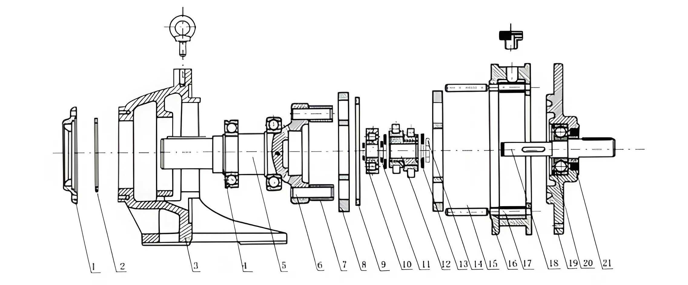
Our design philosophy was to innovate within the proven two-stage reduction paradigm but with a distinct architectural approach. The proposed reducer integrates a primary planetary gear stage with a secondary cycloidal drive stage, yet the implementation differs meaningfully from conventional RV reducers. The core mechanism can be understood through the following sequential operation:
- First Stage (Planetary Gear Reduction): The input motion is delivered to a sun gear. This sun gear meshes with three planetary gears uniformly distributed around its circumference. These planetary gears, in turn, mesh with a fixed internal ring gear housed within the main casing. The rotation of the sun gear causes the planetary gears to orbit, which drives the planetary carrier. The planetary carrier is rigidly connected to the output of this first stage.
- Motion Transfer: The planetary carrier is integrally connected to a set of eccentric shafts. Therefore, the rotational output of the carrier directly drives these eccentrics.
- Second Stage (Cycloidal Drive Reduction): Each eccentric shaft drives a cycloidal drive disc (or “abnormal cycloidal gear”). This disc does not have traditional gear teeth. Instead, its outer periphery contains a precise circular array of holes housing needle rollers. These needle rollers engage with another set of needle rollers fixed in the stationary main housing (or “shell”). As the eccentric shaft rotates, it imparts a compound oscillating and rotating motion to the cycloidal drive disc. The engagement between the disc’s needles and the housing’s needles converts this eccentric motion into a slow, uniform rotation of the disc itself.
- Final Output: The rotating cycloidal drive disc is connected to an output flange via pins or similar couplings. This flange serves as the final output of the entire reducer, providing high torque at a significantly reduced speed.
The fundamental innovation lies in the secondary stage’s needle-to-needle engagement within a cycloidal drive disc featuring a circular hole pattern, contrasting with the traditional lobed cycloidal disc meshing with stationary pins. The overall transmission ratio is a product of the two stages. For a primary stage with a fixed ring gear, the ratio \( i_1 \) is given by \( i_1 = 1 + \frac{z_3}{z_1} \), where \( z_3 \) is the ring gear teeth and \( z_1 \) is the sun gear teeth. The secondary cycloidal drive stage ratio \( i_2 \) is given by \( i_2 = \frac{z_j}{z_j – z_{lc}} \), where \( z_j \) is the number of needle rollers in the housing and \( z_{lc} \) is the number of needle rollers in the cycloidal drive disc. The total ratio \( i_{total} \) is:
$$ i_{total} = i_1 \times i_2 = \left(1 + \frac{z_3}{z_1}\right) \times \left(\frac{z_j}{z_j – z_{lc}}\right) $$
Based on our initial design goals, we established the key technical parameters, as summarized in the table below.
| Technical Parameter | Symbol | Value |
|---|---|---|
| Total Transmission Ratio | \( i_{total} \) | 273 |
| Module (Stage 1) | \( m \) | 1.25 mm |
| Pressure Angle (Stage 1) | \( \alpha’ \) | 20° |
| Sun Gear Teeth | \( z_1 \) | 12 |
| Planetary Gear Teeth | \( z_2 \) | 30 |
| Ring Gear Teeth | \( z_3 \) | 72 |
| Number of Cycloidal Drive Disc Needles | \( z_{lc} \) | 39 |
| Number of Housing Needles | \( z_j \) | 40 |
| Housing Needle Circle Radius | \( r_j \) | 50.5 mm |
| Eccentricity | \( e \) | 1 mm |
| Rated Output Torque | \( T_{out} \) | 180 N·m |
The three-dimensional model was meticulously constructed in SolidWorks based on these parameters, ensuring proper fit and function of all components, including gears, bearings, shafts, and housing. A key component, the cycloidal drive disc with its precise circular hole pattern for needle rollers, is central to the design. The assembled virtual model demonstrates a compact and integrated structure.
The material selection for critical components is crucial for strength, wear resistance, and dimensional stability. Our choices are listed below.
| Component | Material | Elastic Modulus (GPa) | Poisson’s Ratio |
|---|---|---|---|
| Sun Gear, Planet Gears | 40Cr | 212 | 0.277 |
| Planetary Carrier, Eccentric Shaft, Cycloidal Drive Disc, Needles | GCr15 (Bearing Steel) | 219 | 0.3 |
| Housing, Front/Rear Covers | 45 Steel / 40Cr | 209 / 212 | 0.269 / 0.277 |
2. Mechanical Analysis and Strength Verification
A thorough static force analysis is essential to ensure the structural integrity of the design under the rated load of 180 N·m.
2.1 Force Analysis of the Planetary Gear Stage
With the ring gear fixed and the sun gear as input, the input torque \( T_{in} \) required to achieve the first-stage output torque (to the carrier) is calculated considering efficiency. For a stage ratio \( i_1 = 7 \) and an assumed efficiency \( \eta_1 = 0.9 \), the first-stage output torque \( T_{H} \) is found by back-calculating from the final output:
$$ T_{H} = \frac{T_{out}}{i_2 \cdot \eta_2} $$
Where \( \eta_2 \) is the estimated efficiency of the cycloidal drive stage. An initial estimate gives \( T_{H} \approx 4.62 \) N·m. Consequently, the required input torque is:
$$ T_{in} = \frac{T_H}{i_1 \cdot \eta_1} \approx 0.73 \text{ N·m} $$
The tangential force \( F_t \) between the sun gear and a single planet gear is:
$$ F_{t21} = \frac{2 T_{in}}{3 \cdot m \cdot z_1} $$
The factor 3 accounts for the three planet gears sharing the load. The radial force \( F_r \) is \( F_r = F_t \cdot \tan(\alpha’) \). The resultant normal meshing force \( F_{n12} \) is:
$$ F_{n12} = \sqrt{F_{t21}^2 + F_{r21}^2} $$
Substituting values yields \( F_{n12} \approx 34.5 \) N. This force is used for strength verification of the most critically loaded gear—the sun gear—as it has the smallest diameter.
2.1.1 Sun Gear Strength Check
We performed both contact stress (pitting resistance) and bending stress (root breakage) checks according to standard gear design procedures. The contact stress \( \sigma_H \) and allowable contact stress \( \sigma_{HG} \) are calculated as:
$$ \sigma_H = Z_H Z_E Z_\epsilon \sqrt{\frac{F_{t21}}{b \cdot d_1} \cdot \frac{u+1}{u}} \cdot \sqrt{K_A K_V K_{H\alpha} K_{H\beta}} \leq \sigma_{HG} $$
$$ \sigma_{HG} = \sigma_{H \lim} Z_{NT} Z_L Z_V Z_R Z_W Z_X $$
The bending stress \( \sigma_F \) and allowable bending stress \( \sigma_{FE} \) are:
$$ \sigma_F = \frac{F_{t21}}{b \cdot m} Y_{Fa} Y_{Sa} Y_\epsilon \cdot K_A K_V K_{F\alpha} K_{F\beta} \leq \sigma_{FE} $$
$$ \sigma_{FE} = \frac{\sigma_{F \lim}}{S_{Fmin}} Y_{ST} Y_{NT} Y_{\delta rel T} Y_{R rel T} Y_X $$
Using appropriate coefficients for material 40Cr, geometry, and application, the results are summarized below:
| Check Type | Calculated Stress (MPa) | Allowable Stress (MPa) | Safety Factor |
|---|---|---|---|
| Contact Stress (Pitting) | 28.6 | 715 | > 25 |
| Bending Stress (Root) | 17.0 | 337.4 | > 19.8 |
The significant safety margins confirm the planetary gear stage is robustly designed for the rated load.
2.2 Force Analysis of the Cycloidal Drive Stage
The force transmission in the needle-engagement cycloidal drive is more complex. The force on an individual needle roller in the disc is not uniform. It is proportional to the distance \( l_i \) from the disc’s center to the line of action of the force at the contact point. The maximum force \( F_{max} \) occurs at the needle experiencing the greatest leverage arm \( l_{max} \). For a cycloidal drive disc with a circular hole pattern, the relationship between the torque transmitted by one disc \( T_C \) and \( F_{max} \) can be derived as:
$$ T_C = \sum_i F_i l_i = \frac{F_{max}}{r_{lc}} \sum_i l_i^2 = F_{max} \cdot r_{lc} \cdot z_{lc} \cdot \left[ \frac{\sum_i l_i^2}{r_{lc}^2 \cdot z_{lc}} \right] $$
Where \( r_{lc} \) is the pitch radius of the cycloidal drive disc needle circle, approximately equal to \( l_{max} \). The bracketed term is a geometrical factor. Analysis shows this factor is approximately 0.25 for our design, simplifying the equation to:
$$ T_C \approx \frac{F_{max} \cdot r_{lc} \cdot z_{lc}}{4} $$
Considering load sharing between two phase-shifted cycloidal drive discs (a common practice for balance), one disc may carry up to 55% of the total output torque, i.e., \( T_C = 0.55 \cdot T_{out} \). Knowing that \( r_{lc} = k_1 \cdot r_j \), where \( k_1 \) is the shortening coefficient, we can solve for \( F_{max} \):
$$ F_{max} = \frac{2.2 \cdot T_{out}}{k_1 \cdot r_j \cdot z_{lc}} $$
Substituting \( T_{out} = 180 \) N·m, \( k_1 \approx 0.92 \), \( r_j = 0.0505 \) m, and \( z_{lc} = 39 \), we find \( F_{max} \approx 254.5 \) N.
2.2.1 Contact Stress in Needle Engagement
The contact between the housing needle and the cycloidal drive disc needle is modeled as the contact between two parallel cylinders. The maximum contact stress is calculated using the Hertzian contact formula:
$$ \sigma_{Hn} = 0.418 \sqrt{ \frac{F_{max} \cdot E_c}{b_c \cdot \rho_i} } $$
Where:
- \( E_c \) is the combined elastic modulus: \( \frac{2}{E_c} = \frac{1-\nu_1^2}{E_1} + \frac{1-\nu_2^2}{E_2} \). For identical GCr15 steel needles, \( E_c \approx 113 \) GPa.
- \( b_c \) is the effective contact length of the needle (the width of the cycloidal drive disc).
- \( \rho_i \) is the radius of the needle (2.5 mm).
Calculating with \( b_c = 9 \) mm yields \( \sigma_{Hn} \approx 465 \) MPa. This is well below the allowable contact stress for hardened bearing steel (typically 1200-1500 MPa), confirming the safety of the cycloidal drive engagement under rated load.
3. Virtual Prototyping and Dynamic Simulation
To validate the kinematic and dynamic behavior before physical manufacturing, we conducted multi-body dynamics simulations using Adams.
3.1 Transmission Ratio and Error Analysis
The virtual model was assembled with proper joints (fixed, revolute, contacts) and constraints. A step rotational velocity was applied to the sun gear input. The simulation yielded the angular velocities of the planetary carrier (first-stage output) and the final output flange. The results were compared with theoretical values.
| Component | Theoretical Angular Velocity (°/s) | Simulation Average (°/s) | Relative Error |
|---|---|---|---|
| Input Sun Gear | 9000.0 | 9000.0 | 0% |
| Planetary Carrier | 1285.8 | 1278.6 | 0.56% |
| Output Flange | 33.0 | 33.1 | 0.39% |
The simulated total transmission ratio was 271.88, closely matching the theoretical design ratio of 273 (error ~0.41%). The small discrepancies are attributed to numerical simulation tolerances and simplified contact models, confirming the correctness of the kinematic design.
3.2 Transmission Efficiency Estimation
The total theoretical efficiency \( \eta_{total} \) of the reducer is the product of the efficiencies of its stages and the supporting bearings:
$$ \eta_{total} = \eta_{gear} \cdot \eta_{cycloidal} \cdot \eta_{bearings} $$
Planetary Stage Efficiency (\( \eta_{gear} \)): For a fixed ring gear planetary train, the power loss is primarily due to sliding friction in the gear meshes. An approximate formula considering multiple planet gears is used for estimation.
Cycloidal Drive Stage Efficiency (\( \eta_{cycloidal} \)): The efficiency of the needle-based cycloidal drive is influenced by sliding friction at the engagement points. It can be estimated by:
$$ \eta_{cycloidal} \approx 1 – \mu_c \cdot \frac{c}{k_1} \left(1 – \frac{r_{lc}}{r_j}\right) $$
where \( \mu_c \) is the coefficient of friction (~0.06) and \( c \) is a sliding coefficient related to the number of housing needles.
Bearing Efficiency (\( \eta_{bearings} \)): The efficiency of needle roller and deep groove ball bearings is typically very high, with a combined estimate of 0.98.
Combining these estimates, the overall theoretical efficiency was calculated to be approximately 92.4%.
Simulation-based Efficiency: In Adams, with an input torque of 0.73 N·m, the steady-state output torque was measured. The simulated efficiency \( \eta’ \) is:
$$ \eta’ = \frac{T_{out, sim}}{T_{in} \cdot i_{total}} \times 100\% $$
The simulation yielded an output torque of ~164.6 N·m, corresponding to an efficiency of 91.4%, which aligns well with the theoretical prediction.
3.3 Meshing Force Verification
The simulation provided dynamic meshing force data. The average normal force between the sun and planet gears was ~32.6 N, and between the planet and ring gear was ~33.2 N, both consistent with the theoretical static calculation of 34.5 N. For the cycloidal drive stage, the simulated maximum needle contact force averaged ~250.8 N, closely matching the analytically derived value of 254.5 N. These results validate our force analysis models.
4. Prototype Fabrication, Testing, and Performance Benchmarking
4.1 Prototype Manufacturing and Assembly
Based on the finalized design, all critical components were manufactured. The gears were produced via gear hobbing (external) and shaping (internal). The cycloidal drive discs required high-precision machining for their circular hole patterns, involving drilling, boring, and fine grinding. Key components like gears, the eccentric shaft, and the cycloidal drive discs were heat-treated (e.g., carburizing and hardening for GCr15) to achieve the necessary surface hardness and core toughness. The components were then carefully assembled, ensuring proper bearing preload and gear backlash.
4.2 Experimental Setup
Testing was conducted on a dedicated precision reducer test bench. The setup included high-resolution rotary encoders on both the input and output shafts to measure angular position, and torque sensors to measure input and output torque. The system was controlled by specialized software for data acquisition and analysis.
4.3 Key Performance Test Results
4.3.1 Transmission Error (Backlash)
Transmission error \( \theta_{er} \) is a critical measure of precision, defined as the difference between the theoretical and actual output position for a given input:
$$ \theta_{er} = \frac{\theta_{in}}{i_{total}} – \theta_{out} $$
The test involved rotating the input slowly while recording the output position. The peak-to-peak transmission error was extracted from the recorded curve.
- Forward Rotation: Maximum error = 60.25 arc-seconds, Minimum error = -43.12 arc-seconds. Peak-to-peak error = 103.37 arc-seconds.
- Reverse Rotation: Maximum error = 56.09 arc-seconds, Minimum error = -51.33 arc-seconds. Peak-to-peak error = 107.42 arc-seconds.
4.3.2 Transmission Efficiency
The efficiency test involved loading the output from zero to the rated torque while measuring input and output power. The efficiency \( \eta_{test} \) is calculated as:
$$ \eta_{test} = \frac{T_{out, measured} \cdot \omega_{out}}{T_{in, measured} \cdot \omega_{in}} \times 100\% $$
The steady-state efficiency at rated load was measured.
- Forward Rotation: Maximum efficiency = 82.34%.
- Reverse Rotation: Maximum efficiency = 81.62%.
4.4 Comparative Analysis with Industry Standards
We benchmarked our prototype’s performance against the Chinese National Standard GB/T 37718-2019 for precision planetary cycloidal drive reducers, which specifies requirements for models like the RV-20E, a comparable size/capacity reducer.
| Performance Indicator | Our Prototype Test Result | GB/T 37718-2019 Reference (e.g., for RV-20E) | Assessment |
|---|---|---|---|
| Transmission Error (Peak-to-Peak) | ~105 arc-seconds | ≤ 70 arc-seconds (Typical requirement) | Slightly higher, needs optimization. |
| Transmission Efficiency (at rated load) | ~82% | ≥ 80% (Typical requirement) | Meets and slightly exceeds the standard. |
5. Conclusion and Outlook
This work has successfully detailed the complete development cycle of a novel two-stage precision reducer integrating a planetary stage with a needle-based cycloidal drive. The key findings are:
- Feasibility Confirmed: The proposed transmission principle is mechanically sound and functionally viable. The kinematic design, verified by both theory and Adams simulation, accurately achieves the target high reduction ratio.
- Structural Integrity: Comprehensive static force analysis and strength checks confirm that all critical components, including the sun gear and the needle contacts in the cycloidal drive, possess ample safety margins under the rated 180 N·m load.
- Performance Validation: The fabricated prototype demonstrated measurable performance. Its transmission efficiency of approximately 82% meets the threshold set by relevant national standards. The transmission error, while slightly higher than the premium benchmark, is in a comparable range, indicating a fundamentally precise design.
- Areas for Improvement: The primary gap lies in further reducing the transmission error. This is likely attributable to cumulative manufacturing and assembly tolerances in the prototype, particularly in the precision of the cycloidal drive disc hole pattern, eccentric shaft accuracy, and gear quality. Future work will focus on implementing tighter tolerances, exploring selective assembly, and applying targeted compensation techniques (e.g., slight modifications to the cycloidal drive disc hole pattern) to minimize error.
In summary, this novel cycloidal drive-based reducer architecture presents a promising alternative pathway for high-performance robotic reducers. It demonstrates that through innovative structural design, it is possible to achieve competitive performance metrics. With further refinement in manufacturing precision and possible design optimization, this approach has the potential to contribute to the advancement of domestic high-end precision reducer technology.