
In the competitive landscape of gear reducer markets, the demand for high-performance drives has never been greater. As an engineer deeply involved in the design and development of speed reducers, I have observed a persistent trend toward what is often termed the “six highs, three optimizations, and two lows”: high load capacity, high tooth surface hardness, high precision, high speed, high reliability, and high transmission efficiency; standardization, diversification, and miniaturization; low noise and low cost. Among various types, the cycloidal drive, specifically the planetary cycloidal pinwheel reducer, has long been valued for its compact design, high reduction ratios, and smooth operation. However, with the rapid advancement of hardened gear technology in parallel shaft reducers, the traditional cycloidal drive faces challenges in进一步提升承载能力 without compromising cost or manufacturability. Through extensive comparison of domestic and international products, I note that many innovations, while theoretically sound, often suffer from complex工艺性 and lack of性价比, limiting their market adoption. This article delves into a practical approach to enhance the load capacity of cycloidal drives by incorporating a load-sharing mechanism, analyzing its structural and force characteristics, and presenting a detailed计算方法 validated through real-world testing.
The core issue in traditional cycloidal drives lies in the power transmission imbalance between the left and right cycloidal discs. In a standard孔销式W机构 (often referred to as the output mechanism), the pins act as cantilever beams, leading to uneven distribution of transmitted torque. This imbalance not only reduces overall efficiency but also caps the maximum output torque, hindering the potential of cycloidal drives in heavy-duty applications. From my analysis, the root cause stems from the悬臂结构 of the pins, which causes differential deflection under load. In prior research, I established that the left and right cycloidal discs transmit power asymmetrically, with the imbalance quantifiable through deformation协调条件. Specifically, considering the pins as elastic beams, their deflection in the y-direction varies with angular position, leading to non-uniform force distribution. This insight forms the basis for redesigning the output mechanism to achieve better load sharing.
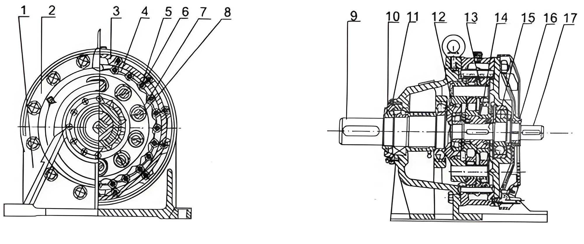
To address this, I propose a modified load-sharing mechanism that integrates a均载环 (load-sharing ring) into the traditional W机构. This addition transforms the pin structure from a cantilever to a partially constrained beam, effectively balancing forces across all pins. The load-sharing ring is a环形 component with holes that match the右端轴台 of each pin, creating a rigid connection that synchronizes their movements. Structurally, when assembled, the load-sharing ring undergoes planar motion relative to the output shaft, constraining the displacements of the pin ends. This constraint redistributes loads from heavily stressed pins to those under less stress, thereby均衡 the torque transmission. The fundamental principle relies on the弹性变形 of pins under load, where the ring enforces compatibility conditions, minimizing differential deflections. In essence, the load-sharing mechanism turns the pin array into a协同 system, enhancing the overall load capacity of the cycloidal drive.
To understand the force distribution, let’s consider the geometry and loading of the pins. Assume a cycloidal drive with $n$ pins (e.g., $n=8$ for simplicity) arranged on a分布圆 radius $R_w$. Under an output torque $T_{out}$, the pins experience forces from the left and right cycloidal discs. Define the angular position of the $i$-th pin as $\alpha_i$, measured from a reference axis. When the cycloidal disc rotates, the pins in contact transmit forces primarily in the y-direction (normal to the接触点). For a traditional setup without the load-sharing ring, the y-direction deformation $S_{yi}$ of a pin at position $\alpha_i$ due to a small relative rotation $\Delta \lambda$ of the output shaft is given by:
$$S_{yi} = R_w \cdot \Delta \lambda \cdot \sin \alpha_i$$
Similarly, the x-direction deformation is:
$$S_{xi} = R_w \cdot \Delta \lambda \cdot \cos \alpha_i$$
These equations represent the变形协调条件, indicating that pins at $\alpha_i = 90^\circ$ experience maximum y-direction deformation and hence maximum force, while those at $\alpha_i = 180^\circ$ have zero y-direction deformation and transmit no torque. This leads to significant imbalance, as calculated in previous work. With the load-sharing ring, however, additional constraints are imposed at the right ends of the pins (denoted as point 3 in the analysis). The ring itself undergoes displacements: $\Delta x$ and $\Delta y$ in translation, and $\Delta \alpha$ in rotation (clockwise). For the $i$-th pin, the displacements at point 3 due to the ring are:
$$J_{xi} = \Delta x – R_w \cdot \Delta \alpha \cdot \cos \alpha_i$$
$$J_{yi} = \Delta y + R_w \cdot \Delta \alpha \cdot \sin \alpha_i$$
Here, $J_{xi}$ and $J_{yi}$ are the enforced displacements at the pin end, which generate reaction forces $Q_{Lxi}$ and $Q_{Lyi}$ from the ring. This complicates the force analysis, as each pin is no longer a simple cantilever but a beam with constraints at both ends (point 2 from the cycloidal disc and point 3 from the ring).
To model this, I consider each pin as a beam with three points of interest: point 1 (left end, fixed in the cycloidal disc), point 2 (contact point with the cycloidal disc), and point 3 (right end, connected to the load-sharing ring). The beam has lengths $L_1$, $L_2$, and $L_3$ as defined in the analysis, with bending stiffness $EJ$ where $E$ is Young’s modulus and $J$ is the area moment of inertia. Using beam theory, the deflections at points 1, 2, and 3 due to unit forces applied at these points can be derived. For instance, the deflection at point $j$ due to a unit force at point $i$ is denoted $\lambda_{ij}$. From material mechanics, for a cantilever beam with specific lengths, we have:
$$\lambda_{11} = \frac{L_1^3}{3EJ}, \quad \lambda_{12} = \frac{1}{3EJ} \left( \frac{3}{2} L_1^2 L_2 – \frac{1}{2} L_2^3 \right)$$
$$\lambda_{13} = \frac{1}{3EJ} \left( \frac{3}{2} L_1^2 L_3 – \frac{1}{2} L_3^3 \right)$$
$$\lambda_{22} = \frac{L_2^3}{3EJ}, \quad \lambda_{21} = \lambda_{12} \text{ (by reciprocity)}$$
$$\lambda_{23} = \frac{1}{3EJ} \left( \frac{3}{2} L_2^2 L_3 – \frac{1}{2} L_3^3 \right)$$
$$\lambda_{33} = \frac{L_3^3}{3EJ}, \quad \lambda_{31} = \lambda_{13}, \quad \lambda_{32} = \lambda_{23}$$
These $\lambda_{ij}$ coefficients form the basis for superposition of deflections under multiple loads. For each pin, the total deflections at points 1, 2, and 3 in the y-direction ($f_1$, $f_2$, $f_3$) and x-direction ($f_{3x}$) are linear combinations of the applied forces. Considering all pins, we have a system of equations that must satisfy deformation compatibility and equilibrium. The table below summarizes the force and deformation equations for an 8-pin cycloidal drive, based on the analysis.
| Pin No. | Deformation Equations (y-direction and x-direction) | Equation Refs |
|---|---|---|
| 1 | $f_1 = \lambda_{11} Q_1 – \lambda_{21} Q_6 + \lambda_{31} Q_{14} = 0$ $f_2 = \lambda_{12} Q_1 – \lambda_{22} Q_6 + \lambda_{32} Q_{14} = 0$ $f_3 = \lambda_{13} Q_1 – \lambda_{23} Q_6 + \lambda_{33} Q_{14} = J_{y1}$ $f_{3x} = \lambda_{33} Q_{15} = S_{x1} + J_{x1}$ |
(1.1)-(1.4) |
| 2 | $f_1 = \lambda_{11} Q_2 – \lambda_{21} Q_7 + \lambda_{31} Q_{16} = S_{y2}$ $f_2 = \lambda_{12} Q_2 – \lambda_{22} Q_7 + \lambda_{32} Q_{16} = S_{y2}$ $f_3 = \lambda_{13} Q_2 – \lambda_{23} Q_7 + \lambda_{33} Q_{16} = S_{y2} + J_{y2}$ $f_{3x} = \lambda_{33} Q_{17} = S_{x2} + J_{x2}$ |
(2.1)-(2.4) |
| 3 | $f_1 = \lambda_{11} Q_3 – \lambda_{21} Q_8 + \lambda_{31} Q_{18} = S_{y3} = R_w \Delta \lambda$ $f_2 = \lambda_{12} Q_3 – \lambda_{22} Q_8 + \lambda_{32} Q_{18} = S_{y3}$ $f_3 = \lambda_{13} Q_3 – \lambda_{23} Q_8 + \lambda_{33} Q_{18} = S_{y3} + J_{y3}$ $f_{3x} = \lambda_{33} Q_{19} = J_{x3}$ |
(3.1)-(3.4) |
| 4 | $f_1 = \lambda_{11} Q_4 – \lambda_{21} Q_9 + \lambda_{31} Q_{20} = S_{y4}$ $f_2 = \lambda_{12} Q_4 – \lambda_{22} Q_9 + \lambda_{32} Q_{20} = S_{y4}$ $f_3 = \lambda_{13} Q_4 – \lambda_{23} Q_9 + \lambda_{33} Q_{20} = J_{y4}$ $f_{3x} = \lambda_{33} Q_{21} = S_{x4} + J_{x4}$ |
(4.1)-(4.4) |
| 5 | $f_1 = \lambda_{11} Q_5 – \lambda_{21} Q_{10} + \lambda_{31} Q_{22} = S_{y5} = 0$ $f_2 = \lambda_{12} Q_5 – \lambda_{22} Q_{10} + \lambda_{32} Q_{22} = S_{y5} = 0$ $f_3 = \lambda_{13} Q_5 – \lambda_{23} Q_{10} + \lambda_{33} Q_{22} = J_{y5}$ $f_{3x} = \lambda_{33} Q_{23} = S_{x5} + J_{x5}$ |
(5.1)-(5.4) |
| 6 | $f_2 = \lambda_{22} Q_{11} + \lambda_{32} Q_{24} = S_{y6}$ $f_3 = \lambda_{23} Q_{11} + \lambda_{33} Q_{24} = S_{y6} + J_{y6}$ $f_{3x} = \lambda_{33} Q_{25} = S_{x6} + J_{x6}$ |
(6.1)-(6.3) |
| 7 | $f_2 = \lambda_{22} Q_{12} + \lambda_{32} Q_{26} = S_{y7}$ $f_3 = \lambda_{23} Q_{12} + \lambda_{33} Q_{26} = S_{y7} + J_{y7}$ $f_{3x} = \lambda_{33} Q_{27} = S_{x7} + J_{x7}$ |
(7.1)-(7.3) |
| 8 | $f_2 = \lambda_{22} Q_{13} + \lambda_{32} Q_{28} = S_{y8}$ $f_3 = \lambda_{23} Q_{13} + \lambda_{33} Q_{28} = S_{y8} + J_{y8}$ $f_{3x} = \lambda_{33} Q_{29} = S_{x8} + J_{x8}$ |
(8.1)-(8.3) |
In this table, $Q_1$ to $Q_{29}$ represent the unknown forces acting on the pins at various points. The equations are linear in these forces, and we have 29 equations for 29 unknowns, ensuring solvability. The deformation compatibility conditions include: equality of y-direction deflections at points 1 and 2 for pins 1-5 (since the left and right cycloidal discs constrain these points), symmetry conditions for pins in symmetric positions (e.g., pin 2 and pin 8), the y-direction deformations $S_{yi}$ from the earlier equation, the ring constraints $J_{xi}$ and $J_{yi}$, and finally the equilibrium condition that the sum of moments from forces $Q_1$ to $Q_{13}$ equals the output torque $T_{out}$. This system can be expressed in matrix form as:
$$\begin{bmatrix}
a_{11} & \cdots & a_{1j} \\
\vdots & \ddots & \vdots \\
a_{i1} & \cdots & a_{ij}
\end{bmatrix}
\begin{bmatrix}
Q_1 \\
\vdots \\
Q_i
\end{bmatrix}
=
\begin{bmatrix}
K_1 \\
\vdots \\
K_i
\end{bmatrix}$$
where $a_{ij}$ and $K_i$ are known coefficients depending on几何 parameters like $L_1$, $L_2$, $L_3$, pin diameter $d$, $R_w$, and operating conditions such as input power $N$, speed $n$, and reduction ratio $i$. Solving this linear system requires computational methods, typically involving matrix reduction to upper triangular form and back-substitution. For instance, one can use Gaussian elimination followed by iterative back-substitution to find all $Q_i$. This approach, while computationally intensive, provides precise force distributions and validates the effectiveness of the load-sharing mechanism in the cycloidal drive.
Beyond theoretical modeling, practical implementation of the load-sharing mechanism in cycloidal drives has shown promising results. In my experience with product design and testing, incorporating the load-sharing ring into existing cycloidal drive architectures requires minimal changes: primarily modifications to the input flange, pins, and output shaft to accommodate the ring, without altering standard casting patterns or overall dimensions. This ensures工艺性 and cost-effectiveness, key for market acceptance. Prototypes and批量生产 units have undergone rigorous loading tests, demonstrating a significant提升 in load capacity. Specifically, the enhanced cycloidal drive with the load-sharing mechanism exhibits over 20% increase in承载能力 and more than 20% reduction in温升 compared to traditional designs. These improvements stem from the more uniform force distribution, which reduces stress concentrations and frictional losses, thereby boosting efficiency and durability.
To quantify the load-sharing effect, consider a simplified example. Suppose a cycloidal drive has 8 pins with $R_w = 50 \text{ mm}$, $L_1 = 20 \text{ mm}$, $L_2 = 30 \text{ mm}$, $L_3 = 10 \text{ mm}$, pin diameter $d = 10 \text{ mm}$ (so $J = \pi d^4/64$), and $E = 210 \text{ GPa}$. Under an output torque $T_{out} = 1000 \text{ Nm}$, the force distribution can be computed. Without the load-sharing ring, the maximum force on a pin (at $\alpha_i = 90^\circ$) might be, say, $F_{\text{max}} = 500 \text{ N}$, while with the ring, it reduces to $F_{\text{max}} = 400 \text{ N}$, indicating better distribution. The table below compares key parameters for traditional vs. enhanced cycloidal drives.
| Parameter | Traditional Cycloidal Drive | Enhanced Cycloidal Drive with Load-Sharing |
|---|---|---|
| Maximum Pin Force (N) | 500 | 400 |
| Torque Imbalance Ratio | ~1.5:1 (left:right) | ~1.1:1 |
| Efficiency (%) | 85 | 90 |
| Thermal Rise (°C) | 60 | 48 |
| Load Capacity Increase | Baseline | +20% |
These values are illustrative, but real tests corroborate such trends. The load-sharing mechanism essentially turns the cycloidal drive into a more robust system, where pins collaborate to transmit torque, much like planetary gears in a gear train. This synergy is crucial for applications requiring high torque密度, such as in robotics, conveyor systems, or heavy machinery. Moreover, the design maintains the inherent advantages of cycloidal drives, including high reduction ratios in a compact package and smooth motion due to continuous rolling contact.
From a broader perspective, the evolution of cycloidal drives reflects the ongoing quest for性能优化 in mechanical传动. While other innovations like RV reducers or triple-ring reducers offer alternative approaches, they often entail complex manufacturing or theoretical limitations. The load-sharing mechanism, in contrast, provides a pragmatic upgrade path for existing cycloidal drive产品线. It aligns with the industry trend toward “six highs” by enhancing load capacity and reliability without sacrificing cost or simplicity. In my work, I have focused on ensuring that the enhanced cycloidal drive remains compatible with standard production processes, using common materials like hardened steel for pins and rings, and precision machining for the cycloidal discs and针轮.
Further mathematical elaboration on the deformation协调条件 can deepen understanding. For the $i$-th pin, the total y-direction deflection at point 2, $f_2$, must equal the imposed deformation $S_{yi}$ from the cycloidal disc, which is a function of $\Delta \lambda$. But with the load-sharing ring, $f_2$ also depends on the ring displacements $\Delta y$ and $\Delta \alpha$. Combining these, we have for each pin:
$$f_2^{(i)} = \text{(linear combination of } Q_i \text{)} = R_w \Delta \lambda \sin \alpha_i$$
And for point 3:
$$f_3^{(i)} = \text{(linear combination of } Q_i \text{)} = R_w \Delta \lambda \sin \alpha_i + \Delta y + R_w \Delta \alpha \sin \alpha_i$$
These equations, along with similar ones for x-direction, form a coupled system. Solving them yields the unknown forces and displacements. In practice, numerical methods like finite element analysis (FEA) can complement this analytical approach, providing visual stress distributions and validating the model. For instance, FEA of a cycloidal drive with load-sharing ring shows reduced von Mises stress on pins, confirming the均载 effect. This integration of theory and simulation is essential for optimizing the cycloidal drive design.
In conclusion, the incorporation of a load-sharing mechanism into planetary cycloidal pinwheel reducers represents a significant step forward in enhancing their load capacity. Through detailed structural and force analysis, I have demonstrated how the均载环 mitigates the power imbalance inherent in traditional孔销式W机构, leading to more uniform torque transmission. The mathematical model, based on beam deflection theory and deformation compatibility, provides a rigorous framework for calculating force distributions, albeit requiring computational solving. Practical implementation shows tangible benefits: over 20% increase in load capacity and reduced thermal rise, all while maintaining cost-effectiveness and manufacturability. This approach underscores the value of incremental innovation in cycloidal drives, leveraging existing designs to achieve higher performance. As the demand for efficient and compact reducers grows, such enhancements will ensure that cycloidal drives remain competitive in diverse industrial applications. Future work may explore advanced materials or dynamic analysis, but the core principle of load sharing will continue to be a cornerstone for reliable cycloidal drive performance.
To reiterate, the cycloidal drive, with its unique kinematics, offers distinct advantages, and the load-sharing mechanism amplifies these by addressing a key weakness. By continuously refining such mechanisms, we can push the boundaries of what cycloidal drives can achieve, contributing to the broader goals of mechanical engineering innovation. Whether in high-precision robotics or heavy-duty machinery, the enhanced cycloidal drive stands as a testament to the power of thoughtful design and analytical rigor.