
In my extensive experience with power transmission systems, the cycloidal drive stands out as a compact, high-ratio speed reducer with exceptional smoothness and durability. These drives, often referred to as cycloidal speed reducers or cycloidal gearboxes, are integral to industries ranging from chemical processing and mining to medical equipment. Their unique operating principle, based on planetary motion with cycloidal disc engagement, allows for significant speed reduction in a small envelope. However, the very complexity that grants the cycloidal drive its advantages also makes it susceptible to specific issues during installation, operation, and maintenance. To fully leverage the benefits of the cycloidal drive—extending its service life, reducing operational costs, and maximizing efficiency—a deep, practical understanding of these common pitfalls is essential. This analysis, drawn from first-hand engineering practice, delves into the operational theory and systematically examines the prevalent challenges, offering detailed insights and preventive strategies.
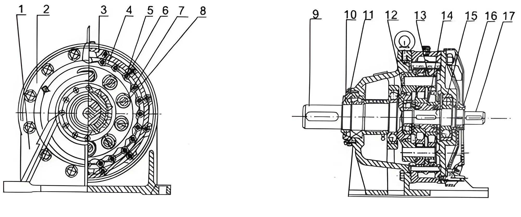
The fundamental operation of a cycloidal drive is an elegant application of epicyclic (planetary) gearing theory. The core mechanism involves the meshing between a lobed cycloidal disc and a stationary ring of cylindrical pins, often fitted with needle bearing sleeves. A typical cycloidal drive assembly comprises three primary sections: the high-speed input, the low-speed output, and the reduction mechanism housing the cycloidal disc and pin ring. The input shaft incorporates a double eccentric cam, with its two throws offset by 180 degrees. Mounted on these eccentric throws via roller bearings (forming an “H” type structure) are one or two cycloidal discs. The bearing rollers fit into the central bore of the cycloidal disc. As the input shaft rotates, it imparts an orbital motion to the cycloidal disc.
The disc’s profile is generated by a hypotrochoid or epitrochoid curve, ensuring continuous engagement with multiple pins simultaneously. This multi-tooth contact is key to the high torque capacity and smooth operation of the cycloidal drive. The motion of the cycloidal disc is a compound one: it undergoes both revolution (eccentric motion around the central axis) and counter-rotation. For each full clockwise rotation of the input shaft and eccentric cam, the cycloidal disc itself rotates slightly counter-clockwise relative to the pin ring. This differential motion is the source of the high reduction ratio. The relationship between the number of pins (Z_p) and the number of lobes on the cycloidal disc (Z_d) determines the reduction ratio (i). In the most common configuration, where the disc has one fewer lobe than the number of pins (Z_d = Z_p – 1), the single-stage reduction ratio is given by:
$$ i = -\frac{Z_p}{Z_p – Z_d} = -Z_p $$
The negative sign indicates the direction reversal between input and output. For a configuration with Z_p = 12 and Z_d = 11, the reduction ratio i = -12. This high ratio in a single stage is a hallmark of the cycloidal drive. The slow rotation of the cycloidal disc is then transmitted to the output mechanism, typically via a set of pins or rollers housed in the output flange that engage with holes in the cycloidal disc, converting the eccentric motion into concentric output rotation. The entire process is characterized by low sliding friction, especially when needle bearing sleeves are used on the stationary pins, leading to high mechanical efficiency often exceeding 90%.
Installing a cycloidal drive correctly is paramount to its long-term performance and reliability. Despite its compact size, improper installation is a frequent root cause of premature failure. I have observed that installation errors often stem from overlooking the device’s specific mechanical limits and alignment requirements. The following table summarizes the critical installation parameters and the consequences of deviation.
| Installation Aspect | Recommended Practice | Common Error & Consequence |
|---|---|---|
| Axial Load on Output Shaft | The output shaft’s axial thrust capacity is limited. Coupling must be achieved using the shaft-end screw for a press-fit connection. | Direct hammering on the shaft to seat the coupling. This can cause immediate bearing damage, shaft scoring, or misalignment. |
| Alignment & Concentricity | Precise alignment of the centerlines and horizontal plane between the cycloidal drive and driven/driving equipment is mandatory. Tolerance should be within manufacturer specifications (often < 0.05mm). | Poor alignment or incorrect leveling. This induces excessive radial loads, leading to accelerated bearing wear, seal failure, and vibration. |
| Lubrication System Integration | If equipped with an external lubrication system, ensure the pump capacity matches the cycloidal drive’s needs and that all lines are clean and secure. | Neglecting to connect or prime an external oil pump. Results in immediate starvation of lubrication and catastrophic failure. |
| Mounting & Foundation | The drive must be mounted on a flat, rigid surface. Use properly sized, symmetrically arranged shims and tighten foundation bolts evenly to avoid housing distortion. | Uneven mounting or soft foot. Causes housing strain, bearing preload issues, and misalignment of internal components. |
| Operating Angle | The cycloidal drive should be installed within a maximum inclination of 15 degrees from the horizontal plane to ensure proper oil sump distribution. | Exceeding the recommended tilt angle. Leads to improper lubrication, where oil pools away from critical components, causing overheating and wear. |
The installation formula for ensuring proper bolt tightening sequence to avoid distortion is akin to applying an even preload. While torque values are specific, the pattern is universal: a star or cross pattern. The stress on the housing (σ_h) from uneven bolting can be approximated, though avoided through procedure:
$$ \sigma_h \propto \frac{F_{bolt} \cdot r}{I} \cdot \sin(\theta_{error}) $$
where $F_{bolt}$ is the bolt force, $r$ is the distance from the bolt to the neutral axis, $I$ is the housing’s moment of inertia, and $\theta_{error}$ represents the angular deviation in the tightening sequence from the ideal pattern.
Operational challenges for the cycloidal drive often arise from boundary condition violations and routine maintenance oversights. In practice, we must adhere to the manufacturer’s specified operating envelope while vigilantly monitoring key parameters. A cycloidal drive is generally designed for continuous duty and reversible operation, but its output assembly has defined limits for axial and radial forces. Exceeding these limits, even momentarily, can have severe consequences. The following analysis, based on field data, outlines the primary operational failure modes.
| Operational Parameter | Requirement | Common Issue & Impact |
|---|---|---|
| Input Power Supply | The driving motor must operate at its nameplate-rated voltage and frequency. | Voltage spikes, sags, or phase imbalance. Causes uneven torque delivery, increased heating in the motor and cycloidal drive, and potential insulation breakdown. |
| Lubricant Selection & Temperature | Oil type (ISO VG) must suit the ambient temperature range. Operating oil temperature should typically remain below 85°C. | Using incorrect viscosity oil or operating in excessive ambient heat. High oil temperature accelerates oxidation, reduces film strength, and can cause thermal expansion leading to clearance loss and seizure. The heat generation ($Q$) can be modeled as: $$ Q \approx (1-\eta) \cdot P_{in} + Q_{friction} $$ where $\eta$ is efficiency and $P_{in}$ is input power. |
| Oil Level Maintenance | Maintain oil level between the minimum and maximum marks on the sight glass or dipstick. | Running with low oil level. Leads to lubrication starvation, excessive wear on the cycloidal disc, needle pins, and bearings. High oil level can cause churning losses and overheating. |
| Oil Change Interval | Initial change after 100-200 hours, then every 3,000-6,000 hours or per manufacturer schedule. Harsh environments (dusty, hot) demand shorter intervals. | Extending oil change intervals indefinitely. Results in lubricant degradation, accumulation of wear particles (abrasives), and loss of anti-wear additives, drastically shortening component life. |
| Overload & Shock Loading | The cycloidal drive output must operate within its rated torque capacity. Shock loads should be minimized. | Frequent jamming or operation above rated torque. Subjects the cycloidal disc, output pins, and bearings to stresses beyond design limits, causing pitting, tooth breakage, or bearing collapse. |
The relationship between load, speed, and service life for bearing components within the cycloidal drive often follows a modified Lundberg-Palmgren equation. For the critical eccentric bearing, the expected life (L10) in hours is inversely proportional to the load cubed:
$$ L_{10} \propto \frac{1}{n} \left( \frac{C}{P} \right)^3 $$
where $n$ is rotational speed, $C$ is the dynamic load rating, and $P$ is the equivalent dynamic load. This highlights why overloading is so detrimental to the longevity of a cycloidal drive.
Proactive and corrective maintenance is the cornerstone of reliable cycloidal drive operation. The device’s compactness belies its internal complexity, making systematic inspection and adherence to repair protocols non-negotiable. From a maintenance perspective, we categorize activities into periodic inspections and targeted repairs. A disciplined inspection regimen can identify issues before they lead to catastrophic failure. The inspection checklist for a cycloidal drive should be comprehensive.
| Inspection Item | Procedure & Standard | Significance of Deviation |
|---|---|---|
| Fastener Tightness & Alignment | Check all coupling, foundation, and cover bolts for proper torque. Re-verify alignment periodically. | Loose fasteners allow movement, breaking alignment and creating destructive cyclic loads. This is a primary initiator of fatigue failures. |
| General Condition & Leaks | Inspect housing for cracks, corrosion, and oil leaks, especially around seals and joints. | Oil leaks indicate seal failure, leading to low oil level and contamination ingress. Cracks can propagate under load. |
| Oil Analysis | Monitor oil level, color, and viscosity. Periodic lab analysis for wear metals (Fe, Cu) and particle count is ideal. | Metallic particles signal active wear of gears or bearings. Water contamination reduces lubricity and promotes rust. |
| Noise & Vibration | Listen for unusual knocking, grinding, or whining. Use vibration analysis to detect bearing defects or imbalance. | Increased noise/vibration is often the first symptom of internal damage, such as pitted bearings, worn pins, or a damaged cycloidal disc. |
| Temperature Monitoring | Regularly measure housing temperature with an infrared thermometer. Compare against a baseline. | Abnormal temperature rise points to excessive friction, overloading, or lubrication failure. The temperature differential ($\Delta T$) can be indicative: $$ \Delta T = T_{housing} – T_{ambient} $$ A sudden increase warrants investigation. |
When disassembly for repair is necessary, precision and correct component handling are critical. The internal geometry of a cycloidal drive is precise; improper reassembly guarantees rapid re-failure. Based on tear-down analyses I have conducted, the following repair points are most sensitive.
| Repair Component | Critical Considerations | Risk of Improper Action |
|---|---|---|
| Shaft Seals | Lip seals are wear items. Replace with OEM-specified seals. Ensure sealing surfaces are smooth and clean during installation. | Reusing worn seals or damaging them during installation. Allows dust, moisture, and abrasive particles to enter, contaminating the oil and accelerating wear. |
| Eccentric Bearings & Needle Pins | Eccentric bearings endure high cyclic loads. Replace during major overhauls. Inspect needle pins and sleeves for scoring or flattening. | Continuing operation with degraded bearings. Leads to increased backlash, vibration, and can cause secondary failure of the cycloidal disc. |
| Cycloidal Disc | Inspect for pitting, cracks, or plastic deformation on the lobe flanks. Minor wear may be acceptable per manufacturer guidelines. | Installing a disc with significant damage. Causes noisy operation, uneven torque transmission, and can fracture under load. |
| Output Mechanism (Pins/Rollers, Wobble Plate) | Check output pins, rollers, and the wobble plate (also called the “interval ring” or “hole plate”) for wear, brinelling, or cracks. Their hardness and surface roughness are critical. | Overlooking wear on the wobble plate or output pins. Creates excessive backlash, reduces positional accuracy, and can lead to fatigue fracture. The contact stress ($\sigma_c$) at these points is high: $$ \sigma_c = \sqrt{\frac{F E^*}{\pi R}} $$ where $F$ is contact force, $E^*$ is equivalent Young’s modulus, and $R$ is effective radius. |
| Reassembly & Sealing | Clean all contact surfaces meticulously. Apply manufacturer-recommended sealant on gaskets or use new, thickness-correct gaskets. Follow prescribed bolt torque sequences. | Using generic RTV sealant excessively or incorrect gasket thickness. Can block internal oil passages or cause housing distortion, affecting internal clearances. |
| Component Interchangeability | Use only matched components from the same manufacturer and model. Do not mix parts from different cycloidal drive units or brands. | Part mixing or substitution. Even slight dimensional or heat treatment differences can disrupt the precise kinematic relationship, causing binding, uneven load sharing, and premature failure. |
Reflecting on the myriad issues that can afflict a cycloidal drive, several root-cause patterns emerge. Often, failures are not isolated events but the culmination of interacting factors. For instance, the common failure of the needle roller bearings on the eccentric shaft (the “rotating arm” bearings) is frequently traced back to lubrication issues—either oil starvation due to low level or the use of degraded oil. The bearings operate under high loads and speeds; insufficient film strength leads directly to metal-to-metal contact and spalling. Similarly, severe wear of the needle pin sleeves is a direct indicator of excessive radial load or misalignment, which increases the specific pressure on these elements.
The design and initial assembly quality of non-gear components like the wobble plate and interval rings are crucial for long-term performance. While minor wear over time is expected, their initial hardness,耐磨性, and surface finish dictate the wear rate. During any repair, verifying these properties is as important as inspecting the gears themselves. Furthermore, the starting method for the driven equipment significantly impacts the cycloidal drive. Frequent direct-on-line starts or starts under high load subject the drive to peak torques several times the running torque, inducing shock loads that can crack the cycloidal disc or damage bearings. Therefore, when specifying a cycloidal drive, the service factor must adequately account for the starting regime and any potential torque spikes in the application. The required service factor (SF) can be conceptualized as:
$$ SF_{required} = f_{load} \cdot f_{start} \cdot f_{ambient} \cdot f_{duty} $$
where the factors account for load character (shock, uniform), start frequency, ambient conditions, and operating duty cycle. Selecting a cycloidal drive with a nameplate service factor lower than the calculated $SF_{required}$ is a recipe for early failure.
In conclusion, the reliable operation of a cycloidal drive hinges on a holistic approach that respects its sophisticated design. From ensuring meticulous alignment and within-specification mounting during installation, through vigilant monitoring of lubrication, load, and temperature in daily use, to executing precise, component-conscious repairs, every phase demands attention to detail. The compactness and high performance of the cycloidal drive are not an invitation to neglect but a mandate for disciplined engineering practice. By internalizing the principles of its operation and the consequences of common errors, maintenance personnel and engineers can transform this remarkable device from a potential maintenance liability into a cornerstone of efficient and reliable mechanical power transmission. The cycloidal drive, when understood and cared for, delivers unparalleled service, but it unequivocally rewards those who invest in its proper stewardship.