
As an engineer deeply involved in the field of precision mechanical transmissions, I have long been fascinated by the cycloidal drive, a mechanism renowned for its high reduction ratios, compact size, and smooth operation. The cycloidal drive, often referred to as a cycloidal speed reducer, is a planetary transmission system that utilizes the meshing of a cycloidal disc with stationary pins to achieve motion conversion. Its advantages, including high efficiency, low noise, and exceptional durability, have made it a staple in various industrial applications, from robotics to heavy machinery. However, through extensive analysis and hands-on experience in manufacturing, I have identified several inherent structural inefficiencies in the conventional cycloidal drive design that hinder modern production workflows. These inefficiencies relate primarily to component complexity, assembly difficulties, and precision challenges. In this article, I will detail a comprehensive structural redesign of the cycloidal drive that addresses these issues, particularly for small-scale units (corresponding to frame sizes 0 through 6 and input power below 1.5 kW). This redesign, which I have developed and validated through practical application, simplifies construction, enhances manufacturability, and reduces costs while preserving the core performance benefits of the cycloidal drive.
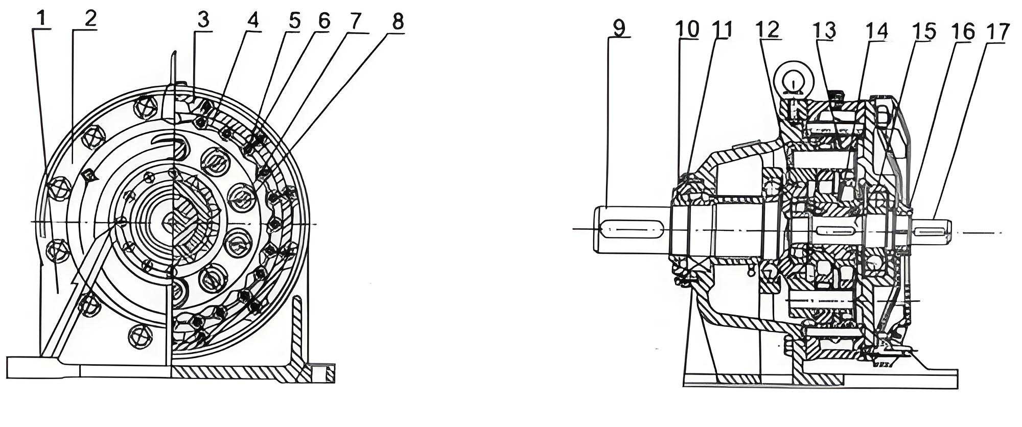
The traditional cycloidal drive, as standardized in many industry specifications, consists of multiple discrete components assembled with tight tolerances. A typical structure includes a housing (机座), a separate pin housing or ring (针齿壳), an output shaft, an input shaft, bearings, seals, retaining rings, spacers, and fastening elements. The assembly process is intricate, relying on precise fits and specialized techniques. For instance, the pin housing requires the accurate machining of numerous pin holes on a precise pitch circle. This is often done using indexing fixtures on drilling machines, a labor-intensive and time-consuming process that depends heavily on skilled labor. Furthermore, the axial fixation of the output and input shafts typically involves shrink-fitting retaining rings, necessitating heating equipment and careful thermal management. The use of spacers between bearings and the reliance on bearings with snap ring grooves add to the part count and assembly steps. From a design perspective, these elements introduce cumulative errors. The housing and pin housing are separate entities; their mating surfaces and alignment features must be machined to high standards of perpendicularity and coaxiality. According to common technical requirements, the coaxiality of the bearing bores relative to the pin housing locating diameter should be at least grade 7, and the perpendicularity of the pin hole axes to the mounting face should be at least grade 6. These requirements, while ensuring performance, make manufacturing and assembly disproportionately challenging for small cycloidal drives, where cost-effectiveness and production speed are paramount.
My redesign fundamentally rethinks this architecture. The most significant change is the integration of the main housing and the pin housing into a single, monolithic component. I refer to this integrated part as the “unified housing” or “monoblock housing.” This eliminates the interface between two separate parts, thereby removing the associated machining of mating faces and locating diameters, and more importantly, eradicating the assembly error stack-up. All critical features—the bearing bores, the pin holes, and the flange mounting diameter—can now be machined in a single setup on a modern machining center. This ensures inherent alignment accuracy that surpasses what can be achieved by assembling two separate pieces. The geometric relationships within a cycloidal drive are governed by precise formulas. The profile of the cycloidal disc is derived from an epitrochoid or hypotrochoid curve. When a cycloidal disc with N lobes rotates inside a ring of Z stationary pins (Z = N + 1), the reduction ratio i is given by:
$$ i = -\frac{Z}{Z – N} = -Z $$
for the standard configuration where the disc has one less lobe than the number of pins. The negative sign indicates direction reversal. The accuracy of the pin circle diameter D_p and the pin hole positions is critical for proper meshing and load distribution. In the conventional design, the pin housing must be manufactured to tight tolerances (e.g., D_p with a tolerance of IT6 or IT7). In the monoblock design, this requirement is transferred to the machining center’s capability, but without the subsequent assembly misalignment. The table below contrasts the key machining and assembly requirements of the traditional versus the redesigned cycloidal drive housing system.
| Aspect | Traditional Cycloidal Drive (Separate Housing & Pin Housing) | Redesigned Cycloidal Drive (Unified Monoblock Housing) |
|---|---|---|
| Number of Main Components | 2 (Housing + Pin Housing) | 1 (Unified Housing) |
| Critical Machining Interfaces | Mating faces, locating diameters on both parts. | None (internal features only). |
| Primary Source of Alignment Error | Assembly cumulative error of two parts. | Machine tool accuracy (single setup). |
| Typical Coaxiality Requirement | Grade 7 between bearing bore and pin housing seat. | Inherently satisfied by single-piece machining. |
| Pin Hole Machining Method | Separate process on pin housing (e.g., indexing drill). | Integrated process in machining center. |
| Material & Machining Volume | Higher total volume; two parts to machine. | Reduced total volume; eliminated interface surfaces. |
The second major improvement in my cycloidal drive redesign concerns the axial fixation of the shafts. The traditional method uses specialized retaining rings that are shrink-fitted onto the shafts. This process is not only cumbersome but also requires additional equipment for heating, making it less suitable for automated assembly lines. In my revised design, I have adopted standard, commercially available elastic snap rings (circlips) for both shaft (axial) and housing (bore) retention. Specifically, the output and input shafts are axially located using shaft-type elastic snap rings that fit into grooves machined directly onto the shafts. Correspondingly, the bearings are retained in the unified housing using bore-type elastic snap rings that seat in grooves machined into the housing bores. This change eliminates several components: the shrink-fit retaining rings, the separate spacer between the two main bearings, and the external retainer plate (压盖) that was previously needed to secure the bearing with the snap ring groove. The sealing arrangement is also simplified; since the cycloidal drive is equipped with a breather, the lip seals can be pressed into place without requiring additional axial clamping features. The force analysis for shaft retention is straightforward. The axial force F_a on the shaft, primarily from preload and operational thrust, must be resisted by the snap ring. The required groove depth h and snap ring strength can be calculated based on material yield strength. For a shaft diameter d, the shear stress τ on the snap ring cross-section of area A is:
$$ \tau = \frac{F_a}{A} $$
The design ensures τ remains well below the allowable stress for the spring steel of the snap ring. This method is not only mechanically sound for the loads encountered in small cycloidal drives but also dramatically streamlines the bill of materials and assembly sequence.
To quantify the benefits, let’s delve into the geometric and kinematic fundamentals of the cycloidal drive. The shape of the cycloidal disc is paramount. Its profile is generated by a point on the circumference of a rolling circle of radius r_r inside a base circle of radius R_b. The parametric equations for a standard cycloid (simplified for a pin-cycloid engagement) can be expressed as:
$$ x = (R_b – r_r) \cos \theta + e \cos\left(\frac{R_b – r_r}{r_r} \theta \right) $$
$$ y = (R_b – r_r) \sin \theta – e \sin\left(\frac{R_b – r_r}{r_r} \theta \right) $$
where e is the eccentricity of the crankshaft, and θ is the input rotation angle. In practice, for a cycloidal drive with pins, the disc profile is often a equidistant curve offset from this theoretical trochoid by the radius of the pins r_p. The precise calculation of this profile and the corresponding pin centers is critical for low backlash and high torque capacity. In the monoblock housing, the positional accuracy of the pin holes directly defines the pin center circle. Machining these holes in a single setup with a high-precision machining center ensures that the pin circle diameter D_p and the angular position of each hole meet strict tolerances. The cumulative pitch error ΔF_p across all pins, which affects transmission error and noise, can be controlled to within micrometers. The relationship between manufacturing errors and transmission error is complex, but a simplified model shows that error in pin position δ can cause an angular output error Δφ approximated by:
$$ \Delta \phi \approx \frac{2 \delta}{D_p} \cdot \frac{1}{i} $$
where i is the reduction ratio. By minimizing δ through integrated machining, the redesigned cycloidal drive achieves smoother operation.
The advantages of this structural redesign are multifaceted and significant. First, manufacturing efficiency is greatly enhanced. The unified housing reduces raw material usage by eliminating the flange and web material needed for joining two separate castings or forgings. More importantly, it slashes machining time. Operations like facing, turning, and boring of mating surfaces are completely omitted. The pin holes, which were a bottleneck, can now be drilled, reamed, or even gun-drilled in a continuous automated cycle on the machining center, leveraging its rotary table and tool magazine. This is a leap from craft-based production to modern, scalable manufacturing. Second, assembly is simplified and faster. The reduction in part count is substantial. The following table provides a comparative parts list for a typical small cycloidal drive assembly.
| Component Category | Traditional Cycloidal Drive Count | Redesigned Cycloidal Drive Count | Notes on Change |
|---|---|---|---|
| Housing Bodies | 2 (Main Housing, Pin Housing) | 1 (Unified Housing) | Merged into one. |
| Shaft Retention | 2 Shrink-fit Rings, 1 Spacer, 1 Retainer Plate | 2 Elastic Snap Rings (shaft type) | Eliminated spacer, retainer plate, and special rings. |
| Bearing Retention | 2 Snap Rings (for bearing with groove) or Retainer | 2 Elastic Snap Rings (bore type) | Standardized retention method. |
| Fasteners & Misc. | Various bolts, washers for assembly | Reduced number of fasteners | Simplified interface with end cover. |
| Total Distinct Parts | ~15-18 | ~10-12 | ~30% Reduction |
This parts reduction directly translates to lower inventory costs, simpler logistics, and reduced opportunities for assembly errors. Third, performance and reliability are improved. The elimination of the interface between housing and pin housing removes a potential source of fretting corrosion and stiffness variation. The monolithic structure provides better heat dissipation and more uniform load distribution around the pin circle. The use of standard elastic snap rings for axial fixation is perfectly adequate for the axial loads in small cycloidal drives, which are primarily from bearing preload and negligible operational thrust. Their installation is quick, tool-based, and requires no thermal processes, making the assembly line safer and more efficient. Furthermore, the inherent alignment from single-setup machining ensures optimal meshing of the cycloidal disc with the pins, leading to higher transmission efficiency, potentially lower noise, and longer service life. The fundamental kinematics of the cycloidal drive remain unchanged, preserving its high single-stage reduction ratio, which is still defined by:
$$ i = -\frac{Z}{1} = -Z $$
for the standard configuration where the cycloidal disc has one lobe less than the number of pins Z. This core advantage of the cycloidal drive is fully retained.
From a design engineering perspective, the redesign also simplifies tolerance stack-up analysis. In the traditional assembly, the final coaxiality between the input and output shafts is a function of multiple variables: the perpendicularity of the housing face to its bore, the coaxiality of the pin housing to its seat, the parallelism of the pin housing faces, and the bearing fits. The overall system error E_total could be modeled as a root-sum-square of individual errors:
$$ E_{total} = \sqrt{e_1^2 + e_2^2 + e_3^2 + …} $$
where e_1, e_2, … represent errors from each interface and part. In the monoblock design, several of these error sources are consolidated into the machining error of one part, which is easier to control and typically smaller in magnitude. This leads to a more predictable and repeatable product quality. Additionally, the lubrication system benefits from the simpler internal geometry. Oil channels and grooves can be machined more directly into the unified housing, ensuring better oil flow to the pins and bearings, which is crucial for the longevity of the cycloidal drive.
In conclusion, the structural redesign of the cycloidal drive that I have presented—centered on a unified housing and elastic snap ring axial fixation—offers a compelling advancement for small-scale cycloidal speed reducers. It addresses the historical manufacturing and assembly bottlenecks associated with this otherwise excellent transmission technology. By embracing integrated machining and standard retention components, this design aligns the production of cycloidal drives with the demands of modern, cost-sensitive, and high-volume manufacturing environments. The cycloidal drive retains all its iconic performance characteristics: the large reduction ratio, compactness, high efficiency, and smooth operation. This redesign simply makes it easier and more economical to produce without compromising on quality. The cycloidal drive, in this improved form, is poised to find even wider application in precision motion control systems, collaborative robots, medical devices, and any arena where reliable, high-ratio speed reduction in a small package is required. Future work could explore material optimization for the monoblock housing, advanced surface treatments for the pin holes, and further integration of sensor elements for smart monitoring, ensuring the continued evolution of this remarkable mechanical system.