
The increasing frequency and devastating impact of high-rise building fires underscore the critical need for reliable, personal emergency escape systems. While rope-based descent offers a fundamental solution, existing devices often suffer from limitations such as weight-dependent descent speed, complex operation requiring user intervention, or reliance on powered mechanisms. This necessitates the development of a self-regulating, passive, and user-friendly descender. This article presents the design, analysis, and experimental validation of a novel graded-descent apparatus. The core innovation lies in utilizing a cycloidal drive to transform continuous long-distance fall into a series of controlled, short “drop-and-brake” segments. The integrated system, combining a cycloidal drive speed reducer with a hydraulic damping mechanism, automatically adapts to a wide range of user weights without requiring adjustment. A detailed numerical model is established, and finite element analysis (FEA) is performed to verify the structural integrity of critical components. Prototype testing confirms the device’s functionality, safety, and self-adaptive characteristics, offering a new paradigm for emergency escape equipment.
The conceptual design centers on achieving automatic, graded deceleration. The complete descent from a height is broken into intervals of approximately 0.8 to 1.0 meters. Within each interval, the user accelerates in free-fall before a braking phase engages to bring the descent to a momentary halt. This cycle repeats until the ground is reached. The mechanical system devised to execute this principle comprises four main subsystems: a manual rewinding mechanism, a cable drum, a speed reduction unit, and a damping unit.
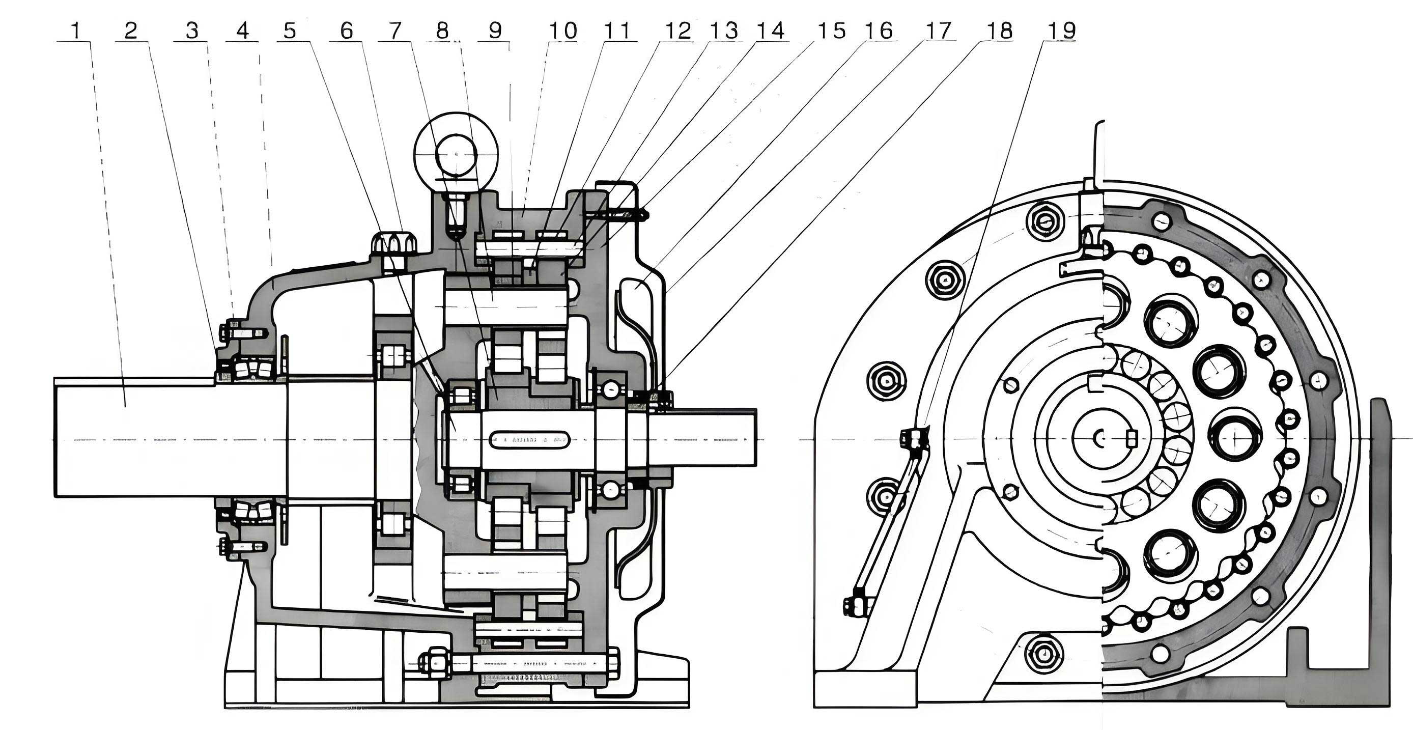
The damping unit is a simple hydraulic cylinder with a piston featuring a one-way check valve and a damping orifice. Fluid flow from the lower chamber to the upper chamber through the small orifice creates a damping force that resists motion, while reverse flow through the check valve is unrestricted. The speed reduction unit is the heart of the timing mechanism. A cycloidal drive harmonic reducer, with its high reduction ratio, is employed. After a predetermined number of rotations of the cable drum (corresponding to the desired descent segment length), the output of the cycloidal drive completes one full revolution. This output is configured as a cam. During the cam’s rise (dwell) period, it presses the piston rod of the hydraulic damper, engaging the braking action. During the cam’s fall (return) period, the piston disengages, allowing free descent. Two overrunning clutches (freewheel mechanisms) are integrated for operational safety and ease: one between the manual rewind handle and the drum prevents the handle from spinning during descent, and another between the drum and the cycloidal drive input reduces resistance during manual cable retrieval.
The operational sequence is as follows: As the user descends, their weight rotates the cable drum. This rotation is transmitted through the first clutch to the input of the cycloidal drive. After several drum rotations, the slow-moving output cam completes its return stroke and begins its rise stroke, compressing the hydraulic damper. The damping force generated opposes the drum’s rotation, decelerating the user to a stop. The cam then moves back to its return stroke, the damping disengages, and the next descent segment begins automatically. This design ensures the descent interval is mechanically fixed, while the speed within the free-fall phase and the braking force automatically scale with the user’s weight via the hydraulic damping principle.
Cycloidal Drive Design and Kinematics
The cycloidal drive was selected for its exceptional qualities: very high single-stage reduction ratios, compactness, high torque capacity, and good efficiency. These attributes make it ideal for transforming the multiple rotations of the cable drum into the single, slow output revolution required to actuate the cam. The basic configuration consists of an input eccentric cam, a cycloidal disk (the lobed element), and a stationary ring of cylindrical pins (the ring gear).
The design process begins with defining the required reduction ratio. Targeting a descent segment length \( L \) of ~1 meter, and given the cable drum’s effective average diameter \( D_{avg} \), the number of drum rotations \( N_{drum} \) per segment is:
$$ N_{drum} = \frac{L}{\pi D_{avg}} $$
For a drum with inner and outer diameters of 63 mm and 102 mm respectively, the average diameter is 82.5 mm, giving \( N_{drum} \approx 3.86 \). Therefore, a reduction ratio \( i \) of approximately 4:1 is needed from the drum to the cam output (\( i = N_{drum} \)). A standard cycloidal drive reduction ratio is given by \( i = Z_p / (Z_p – Z_c) \), where \( Z_p \) is the number of pins in the ring gear and \( Z_c \) is the number of lobes on the cycloidal disk. Selecting \( Z_p = 12 \) and \( Z_c = 9 \) yields \( i = 12 / (12 – 9) = 4 \), perfectly matching the requirement.
The tooth profile of the cycloidal disk is defined by the epitrochoidal/hypocycloidal curve generated as a circle rolls around another circle. The parametric equations for the lobe profile relative to the disk’s center are crucial for accurate modeling and manufacturing. The coordinates of a point on the cycloidal lobe are given by:
$$ x(\theta) = R_c \sin\left(\frac{Z_p}{Z_c} \theta\right) – r_p \sin(\theta) \cos\left(\frac{Z_p}{Z_c} \theta + \theta\right) $$
$$ y(\theta) = R_c \cos\left(\frac{Z_p}{Z_c} \theta\right) + r_p \sin(\theta) \sin\left(\frac{Z_p}{Z_c} \theta + \theta\right) $$
Where:
- \( \theta \) is the generation angle parameter.
- \( R_c \) is the radius of the rolling circle (related to the pin center radius \( R_p \) by \( R_c = R_p \cdot Z_c / Z_p \)).
- \( r_p \) is the radius of the generating point (the roller/pin radius).
- The term \( \frac{Z_p}{Z_c} \theta \) accounts for the different number of lobes and pins.
For structural integration and compactness, the stationary ring of pins is housed within an outer casing whose external profile is machined into the output cam. This cam profile is designed to provide the necessary displacement curve for the hydraulic piston: a rapid-return profile followed by a dwell-rise profile for braking. The motion characteristics of the cycloidal drive ensure smooth transmission of torque from the high-speed, low-torque drum input to the low-speed, high-torque cam output required to activate the damper.
| Parameter | Symbol | Value | Unit |
|---|---|---|---|
| Number of Ring Gear Pins | \( Z_p \) | 12 | – |
| Number of Cycloidal Disk Lobes | \( Z_c \) | 9 | – |
| Theoretical Reduction Ratio | \( i \) | 4 | – |
| Pin Circle Radius | \( R_p \) | 27.0 | mm |
| Pin (Roller) Radius | \( r_p \) | 4.5 | mm |
| Cycloidal Disk Width | \( B \) | 15.0 | mm |
| Eccentricity | \( e \) | 2.0 | mm |
Strength Analysis and Finite Element Modeling
The reliable function of the descender under maximum load is paramount. The cycloidal drive components and the support structure are subjected to significant stresses. Theoretical calculations and Finite Element Analysis (FEA) were employed to verify structural integrity.
The primary failure modes for the cycloidal drive are surface contact fatigue (pitting) at the pin-cycloid interface and bending fatigue at the root of the cycloidal lobes. The contact between a pin and a cycloidal lobe can be approximated as contact between two cylinders. The maximum contact stress \( \sigma_H \) is calculated using the Hertzian contact formula:
$$ \sigma_H = \sqrt{ \frac{F_n}{\pi B} \cdot \frac{1}{\frac{1-\nu_1^2}{E_1} + \frac{1-\nu_2^2}{E_2}} \cdot \frac{1}{\rho} } $$
Where \( F_n \) is the normal load at the contact point, \( B \) is the face width, \( E_1, E_2 \) and \( \nu_1, \nu_2 \) are the elastic moduli and Poisson’s ratios of the materials (typically alloy steel for both), and \( \rho \) is the equivalent curvature radius at the point of contact.
Bending stress at the lobe root is assessed using an adapted form of the Lewis bending equation for gear teeth, incorporating stress concentration factors:
$$ \sigma_b = \frac{K F_t Y_{Fa} Y_{Sa}}{B m_n} $$
Where \( K \) is a combined load factor accounting for dynamic effects, \( F_t \) is the tangential force component, \( Y_{Fa} \) is the lobe form factor (dependent on the cycloidal profile), \( Y_{Sa} \) is the stress correction factor, and \( m_n \) is a reference module. For a cycloidal drive with the specified parameters under a 200 kg (1962 N force) load, preliminary calculations indicated stresses well within the allowable limits for hardened alloy steel.
To obtain a more comprehensive and realistic stress distribution, a full 3D finite element model of the assembled descender was created. The geometry was modeled, simplified by removing small fillets and chamfers non-critical to global stress, and then meshed using tetrahedral solid elements (Solid187 in ANSYS). A fine mesh was applied to the cycloidal drive components and the cam-piston contact area. The model consisted of approximately 860,000 elements. Materials were assigned: Structural steel (E=206 GPa, ν=0.3) for the frame, drum, and cycloidal drive parts, and Aluminum (E=69 GPa, ν=0.33) for the hydraulic cylinder housing. A fixed constraint was applied to the base plate, and a static load equivalent to a 200 kg mass acting on the cable drum was simulated.
| Component Group | Material | Elastic Modulus (E) | Poisson’s Ratio (ν) | Boundary Condition |
|---|---|---|---|---|
| Frame, Drum, Cycloidal Parts | Alloy Steel | 206 GPa | 0.30 | N/A |
| Hydraulic Cylinder Body | Aluminum Alloy | 69 GPa | 0.33 | N/A |
| Base Plate | Alloy Steel | 206 GPa | 0.30 | Fixed Support |
| Cable Drum Shaft | Alloy Steel | 206 GPa | 0.30 | Load: 1962 N Force |
The FEA results provided valuable insights. The maximum von Mises stress in the stationary pin gear occurred at the contact points with the cycloidal disk, validating the Hertzian contact analysis. The stress in the cycloidal disk lobes was slightly higher but still significantly below the yield strength of the material. The highest stress in the overall assembly was found at the connection points between the vertical support plates and the base plate, a result of the bending moment induced by the hanging load. This pinpointed a location for potential design reinforcement, such as adding gussets or increasing the plate thickness locally. The analysis confirmed that the core cycloidal drive mechanism and the main frame were adequately designed for the specified safety load.
Hydraulic Damping and System Dynamics
The self-adapting feature of the descender is achieved through the hydraulic damping unit. The damping force \( F_d \) generated by fluid being forced through a small orifice is governed by the equation:
$$ F_d = \frac{\rho A_p^3}{2 C_d^2 A_o^2} v^2 $$
or for laminar flow conditions,
$$ F_d = \frac{12 \mu L A_p^2}{\pi d_o^4} v $$
Where:
- \( \rho \) is the fluid density.
- \( A_p \) is the piston area.
- \( C_d \) is the discharge coefficient of the orifice.
- \( A_o \) and \( d_o \) are the orifice area and diameter, respectively.
- \( \mu \) is the dynamic viscosity of the fluid.
- \( L \) is the length of the orifice.
- \( v \) is the piston velocity.
The quadratic relationship with velocity in turbulent flow is particularly significant. During the braking phase, the cam pushes the piston down. The force the cam must exert (and thus the torque required from the cycloidal drive output) is directly related to this damping force. A heavier user will cause the drum and thus the cycloidal drive input to rotate faster during the free-fall phase. This results in a higher angular velocity for the cam during its rise stroke, leading to a higher piston velocity \( v \). Since the damping force \( F_d \) increases with \( v \) (or \( v^2 \)), the braking force automatically increases for a heavier user, effectively modulating the deceleration. This intrinsic feedback loop is what allows the device to function without manual adjustment.
The system’s dynamic behavior can be modeled by coupling the equations of motion for the falling mass with the kinematics of the cycloidal drive and the force from the hydraulic damper. The equation during the free-fall (cam return) phase is simply:
$$ m \ddot{z} = mg – T $$
where \( m \) is the mass, \( z \) is the vertical position, \( g \) is gravity, and \( T \) is a small, constant frictional torque in the system. During the braking (cam rise) phase, the equation becomes:
$$ m \ddot{z} = mg – \frac{2}{D_{drum}} \left( \tau_{cam}(\theta, \dot{\theta}) + \tau_{fric} \right) $$
Here, \( \tau_{cam} \) is the torque at the cam shaft, which is a function of the cam profile angle \( \theta \) and its angular velocity \( \dot{\theta} \), directly related to the hydraulic damping force \( F_d \). The relationship between the drum rotation and the cam rotation is defined by the reduction ratio \( i \) of the cycloidal drive: \( \theta_{cam} = \theta_{drum} / i \). This system of equations explains the observed performance: a fixed descent segment length (determined by \( i \)) and a descent speed during the free-fall phase that increases with mass, while the braking phase provides proportionally greater deceleration.
Prototype Fabrication and Experimental Validation
A functional prototype was constructed to validate the theoretical and simulation work. Key components like the cycloidal drive (cycloidal disk and pin gear) were precision machined from steel. The hydraulic cylinder was fabricated with a carefully sized damping orifice. The assembly integrated the cable drum, the cycloidal drive reducer, the cam, the damper, and the overrunning clutches into a compact frame.
Experimental tests were conducted by deploying the device from a fixed height of 6.5 meters (simulating a third-story window). Three different loads were used: 15 kg (dummy weight), 40 kg (dummy weight), and 64 kg (a human test subject). The total descent time and the behavior in each segment were recorded.
| Test Load (kg) | Total Descent Height (m) | Average Segment Length (m) | Total Descent Time (s) | Average Descent Speed (m/s) | Observations |
|---|---|---|---|---|---|
| 15 | 6.5 | ~0.80 | 7.8 | 0.83 | Smooth, pronounced stop at each cycle. |
| 40 | 6.5 | ~0.80 | 6.4 | 1.02 | Faster free-fall, stronger but controlled brake. |
| 64 | 6.5 | ~0.81 | 5.3 | 1.23 | Consistent segment length, firm braking, user-reported stability. |
The results conclusively demonstrate the key features of the design. First, the descent segment length remained constant (~0.8 m) regardless of the load, confirming the fixed mechanical timing provided by the cycloidal drive reduction ratio. Second, the average descent speed increased with load, from 0.83 m/s for 15 kg to 1.23 m/s for 64 kg. This is a direct consequence of the system dynamics: heavier loads achieve higher velocities during the free-fall portion of the cycle. Crucially, the hydraulic damping provided proportionally greater braking force, as evidenced by the controlled and safe stop in each cycle even at the highest load. The human subject test confirmed the device’s usability and the non-jarring nature of the graded descent.
Conclusion and Advantages
The development of this novel descender successfully addresses major limitations of existing emergency escape devices. By harnessing the high-ratio, compact power transmission of a cycloidal drive to regulate a hydraulic damping brake, the system achieves automatic, weight-adaptive, graded descent. The integration of the cycloidal drive is pivotal, as it provides the precise mechanical timing needed to segment the fall while operating reliably under impact loads.
The principal advantages of this cycloidal drive-based apparatus are:
- Automatic Speed Regulation: No user adjustment is needed. The hydraulic damping naturally scales the braking force with the descent velocity, which itself depends on the user’s weight.
- Graded Descent Safety: The repetitive “drop-and-brake” cycle prevents the buildup of excessive kinetic energy, mimicking controlled rappelling techniques but without required skill.
- Simplicity and Reliability: The system is entirely passive, requiring no motors, batteries, or electronic controls. Its operation depends on fundamental mechanical and fluid principles.
- Ease of Use: Operation is intuitive—simply attach the harness and step off. The manual rewind feature allows for easy resetting.
- Compact and Robust Design: The use of a cycloidal drive allows for a high reduction ratio in a small package, contributing to a portable and sturdy device.
Finite Element Analysis confirmed the structural integrity of the critical cycloidal drive components and frame under maximum design load. Experimental testing with varying weights, including a human subject, validated the functional principle, demonstrating consistent segment length and adaptive braking performance. This work establishes a viable and innovative approach to personal emergency escape technology, with the cycloidal drive serving as a key enabler for its mechanical intelligence. Future work may focus on optimizing the cam profile for even smoother force transitions, miniaturizing the package further, and conducting extensive durability cycle testing to establish a definitive service life.