
In my extensive work with precision power transmission systems, I have consistently found the cycloidal drive to be a superior mechanism for applications demanding high torque, compact size, and reliable motion control. The fundamental principle hinges on a planetary configuration where a low-eccentricity input causes a cycloidal disk to mesh with a stationary ring of pins. This engagement creates a smooth, multi-tooth contact that results in a high reduction ratio within a single stage. The mathematical foundation for the tooth profile, a key to its performance, is derived from the epicycloidal and hypotrochoidal family of curves. The standard generating equations for the theoretical tooth profile of a cycloidal disk, relative to a fixed pin circle, are given by:
$$
\begin{aligned}
x &= R_p \sin(\phi) – r_r \sin(\phi + \theta) – A \sin(\phi) \\
y &= R_p \cos(\phi) – r_r \cos(\phi + \theta) – A \cos(\phi)
\end{aligned}
$$
Here, \( R_p \) is the pitch radius of the pin circle, \( r_r \) is the radius of the roller pins, \( A \) is the eccentricity of the input crank, \( \phi \) is the input rotation angle, and \( \theta \) is the angular position on the cycloid, related by \( \theta = \frac{Z_p}{Z_c} \phi \), where \( Z_p \) is the number of pins and \( Z_c \) is the number of lobes on the cycloidal disk (typically \( Z_p – Z_c = 1 \)). The working profile is then the equidistant offset curve of this generated path by the roller radius. The reduction ratio \( i \) for a standard single-stage cycloidal drive is remarkably simple and high: \( i = -Z_c \). The negative sign indicates the direction reversal between the input (eccentric bearing) and the output (cycloidal disk rotation).
The practical implementation of this elegant theory, however, presents significant design and manufacturing challenges. The complex, non-involute tooth profile of the cycloidal disk is difficult to machine with high precision. Furthermore, the load distribution among the multiple simultaneous contact points between the disk and the pins is statically indeterminate and highly sensitive to manufacturing tolerances, assembly clearances, and component deformations. Traditional design methods relying heavily on handbook formulas and physical prototyping are time-consuming and may not reveal stress concentrations or dynamic weaknesses early in the development cycle. This is where modern digital engineering tools become indispensable. In my approach, I utilize a fully integrated workflow from parametric 3D modeling to advanced finite element analysis (FEA) and dynamic simulation. This virtual prototyping methodology allows me to explore the behavior of the cycloidal drive under real-world operating conditions, optimize its components for weight and strength, and predict its dynamic response long before a physical prototype is built. The core of this analysis lies in creating a highly accurate digital twin of the drive assembly.
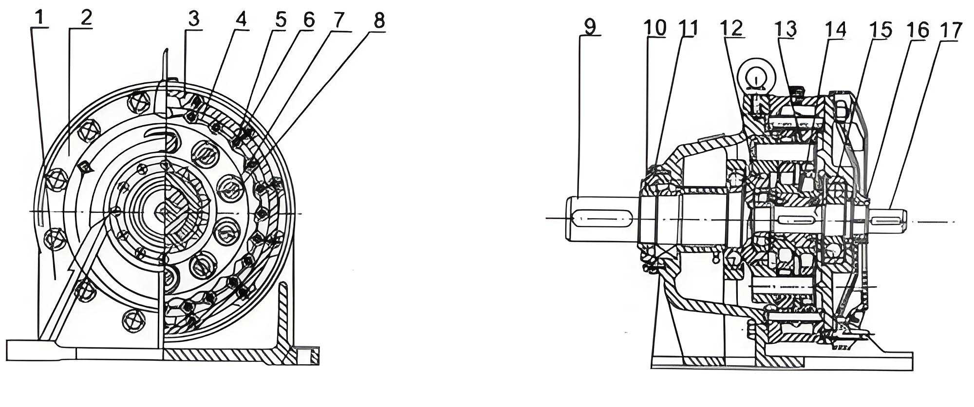
Constructing a reliable digital model begins with precise geometry. I start by defining the key parameters based on the service requirements: input power, speed, desired reduction ratio, and lifetime. For a typical industrial cycloidal drive, common parameters might include an input power of 1-10 kW, input speeds of 1000-3000 rpm, and reduction ratios from 6:1 to over 100:1 in a single stage. Using a parametric CAD system, I generate the cycloidal disk profile programmatically based on the equations mentioned earlier, accounting for the necessary profile modifications (like tooth tip and root relief) to ensure proper lubrication, reduce edge loading, and accommodate manufacturing variances. The other critical components—the pin housing (or ring gear), the eccentric cam assembly with its bearings, the output mechanism (often a set of rollers in holes of the cycloidal disk engaging with pins on the output flange), and the housing—are modeled with careful attention to fit and tolerances. The assembly is constrained to reflect real mechanical joints: fixed connections for bolts and press-fits, revolute joints for bearings, and most importantly, a series of contact conditions between the cycloidal disk lobes and the pin rollers. Defining these contacts correctly is crucial for a meaningful FEA. I model them as non-linear, no-penetration contacts, often with a friction coefficient to represent realistic operating conditions. The material properties assigned are critical for accurate results. I typically use high-performance alloy steels for the cycloidal disk and pins. A common choice is a case-hardened steel like AISI 8620 or a through-hardened bearing steel like AISI 52100 (GCr15). Their properties are defined in the FEA pre-processor as shown in the table below.
| Component | Material | Young’s Modulus (GPa) | Poisson’s Ratio | Yield Strength (MPa) | Density (kg/m³) |
|---|---|---|---|---|---|
| Cycloidal Disk | AISI 8620 (Case Hardened) | 205 | 0.29 | ≥ 1000 (Core) / ≥ 58 HRC (Case) | 7850 |
| Pin Rollers & Output Rollers | AISI 52100 | 210 | 0.30 | ≈ 1700 | 7800 |
| Housing | Ductile Iron (e.g., GGG-40) | 170 | 0.28 | ≥ 250 | 7100 |
| Input/Output Shafts | AISI 4140 | 205 | 0.29 | ≥ 600 | 7850 |
With the assembly prepared, I move to the static structural analysis of the cycloidal drive. The primary goal is to determine the stress and strain distribution in the most critically loaded parts—the cycloidal disk and the pin rollers—under peak torque conditions. Applying the boundary conditions requires careful consideration of the load path. The input torque is applied as a remote force couple on the eccentric cam. The pin housing is fixed to ground. The output flange is constrained to only rotate about its axis, simulating the connection to the driven load. A key challenge is estimating the load sharing among the several meshing teeth. While theoretical models assume equal load distribution among half the pins, in reality, due to deformations, the load is concentrated on a smaller number of pins, often 1/3 of the total or fewer. For a conservative analysis, I often apply the full output torque reaction through a simplified force distribution on the output rollers in the cycloidal disk, which then transfers to the pins via the disk’s deformation. The finite element mesh is refined in the contact regions. For the cycloidal disk, a fine mesh on the tooth flanks is essential to capture the high contact (Hertzian) stresses. The analysis solves for the non-linear contact problem, revealing the von Mises stress distribution.
The results consistently show that the maximum stress occurs not at the pitch point but slightly toward the dedendum of the cycloidal disk tooth, and on the corresponding contact point on the pin roller. This is the region of highest contact pressure. The Hertzian contact stress \( \sigma_H \) between a cylinder (pin roller) and a concave surface (cycloidal tooth) can be approximated for initial verification:
$$
\sigma_H = \sqrt{ \frac{F}{\pi L} \cdot \frac{\frac{1}{R_1} \pm \frac{1}{R_2}}{\frac{1-\nu_1^2}{E_1} + \frac{1-\nu_2^2}{E_2}} }
$$
where \( F \) is the normal load per unit face width \( L \), \( R_1 \) and \( R_2 \) are the radii of curvature (positive for convex), and the `+` sign is used for convex-concave contact. The FEA result should be compared to the allowable contact stress for the chosen material (often in the range of 1500-2500 MPa for hardened steels). A typical result from my static analysis of a mid-size cycloidal drive might show a peak von Mises stress of 1200 MPa in the cycloidal disk subsurface and a contact pressure of 1900 MPa. The safety factor is then evaluated based on the material’s fatigue strength. Furthermore, the deflection of the cycloidal disk is analyzed, as excessive bending can negatively affect the load distribution and lead to uneven wear or even edge loading on the pins. The output mechanism, particularly the pins and holes for the output rollers, is also checked for bearing and shear stress. This comprehensive static analysis validates the structural integrity of the cycloidal drive under load.
Beyond static strength, the dynamic behavior of a cycloidal drive is paramount for applications involving variable loads or high speeds. Modal analysis, performed using the same finite element model (though often with simplified contacts for linear dynamics), reveals the natural frequencies and mode shapes of key components like the input shaft, the cycloidal disk, and the entire assembly. Excitation at or near these frequencies can lead to resonance, causing excessive vibration, noise, and accelerated fatigue failure. For the input shaft, which is subject to the unbalanced mass effect of the eccentric cam, the first few bending modes are of particular interest. I constrain the shaft at the bearing locations and perform a free-vibration analysis. The results typically show the first bending mode occurring at a frequency significantly higher than the input rotational frequency and its harmonics, which is desirable. However, for high-speed cycloidal drives, or those driven by motors with potential torque pulsations, a Campbell diagram can be constructed to ensure no excitation frequencies intersect the natural frequency lines during operation. The table below summarizes a typical modal analysis result for an input shaft assembly.
| Mode Number | Natural Frequency (Hz) | Description of Mode Shape | Criticality Assessment |
|---|---|---|---|
| 1 | 1,250 | First bending, in-plane of eccentricity | Low. Far above typical 1X (16.7-50Hz) and 2X input frequencies. |
| 2 | 1,280 | First bending, orthogonal to mode 1 | Low. Similar separation from excitation. |
| 3 | 3,450 | Second bending | Very Low. |
| 4 | 8,100 | Torsional vibration of shaft | Requires check if driven by servo motor with high frequency ripple. |
For the cycloidal disk itself, its modes are more complex, involving disk-like vibrations such as diametral and circular modes. While these frequencies are usually very high due to the disk’s stiffness, they should be checked in precision applications. The dynamic analysis extends to a transient study where I apply a time-varying load torque to the output. This reveals how stress fluctuates in the components over a loading cycle and is essential for a fatigue life prediction based on stress-life (S-N) or strain-life (ε-N) approaches. I can apply load spectra representative of real duty cycles (e.g., startup, steady operation, shock loads) to estimate the service life of the cycloidal drive. This level of analysis is crucial for designing reliable drives for robotics, aerospace actuators, or heavy machinery where failure is not an option.
The power of integrating FEA into the design cycle of a cycloidal drive is fully realized during the optimization phase. Parameters such as the disk’s thickness, the pin diameter, the eccentricity value, and the size of the output roller holes can be treated as design variables. The objectives are typically to minimize mass (or volume) while constraining the maximum stress to be below a safety factor limit, and sometimes to maximize the first natural frequency to avoid resonance. Using built-in optimization tools, I can set up a design study—like a parametric sweep, design of experiments (DOE), or gradient-based optimization—to automatically run dozens or hundreds of FEA iterations. For instance, I might explore the relationship between cycloidal disk thickness and both its maximum deflection and mass. The results often reveal a non-linear relationship; increasing thickness initially reduces deflection significantly with a modest mass penalty, but after a certain point, the gains in stiffness diminish while mass continues to rise linearly. This helps identify the most efficient design point. Another critical optimization is for the bearing arrangement on the eccentric cam. The forces on these bearings are very high. FEA can help assess different bearing types (needle vs. cylindrical roller) and spacing to minimize shaft deflection and bearing load, thereby increasing the overall lifespan of the cycloidal drive.
Manufacturing considerations must be fed back into the simulation model to ensure robustness. No component is made perfectly. Therefore, I perform sensitivity analyses or deterministic studies with intentional geometric variations. What is the effect of a 0.01 mm profile error on the cycloidal tooth? What if the pin circle has a 0.02 mm radial runout? By simulating these imperfections, I can assess their impact on load distribution and peak stress. This allows me to specify realistic and cost-effective tolerances rather than unnecessarily tight ones. Furthermore, the thermal performance of the cycloidal drive can be analyzed. Under high load and speed, friction in the contacts and in the bearings generates heat. A coupled thermal-structural analysis can model this heat generation and subsequent thermal expansion. Differential expansion between the steel pins and the aluminum or iron housing can affect clearances and preloads, potentially altering the performance and stress state. While often secondary for standard industrial drives, this analysis is vital for high-power density or sealed/lubricated-for-life applications.
| Design Parameter | Typical Range / Formula | Primary Influence | FEA-Guided Optimization Trend |
|---|---|---|---|
| Number of Lobes (Z_c) & Pins (Z_p) | \( Z_p – Z_c = 1 \); \( Z_c \) often 7-31 | Reduction Ratio (\( i = -Z_c \)), Size, Load Sharing | Higher \( Z_c \) gives higher ratio but smaller, weaker teeth. FEA balances contact stress. |
| Eccentricity (A) | \( A \approx (0.5 – 1.2)\% \) of \( R_p \) | Component Size, Bearing Load, Cycloid Profile | Larger A increases bearing forces but can improve torque capacity. FEA optimizes for min. shaft deflection. |
| Pin Roller Diameter (d_r) | \( d_r \approx (0.10 – 0.15) \times R_p \) | Contact Stress, Bending Stress in Disk, Stiffness | Larger \( d_r \) reduces contact pressure but weakens disk web. FEA finds Pareto-optimal diameter. |
| Cycloidal Disk Thickness (t) | Empirical, often \( t \approx (2 – 4) \times A \) | Bending Stiffness, Mass, Bearing Span | Thicker disk reduces deflection and improves load share. FEA finds point of diminishing returns vs. mass. |
| Lobe Profile Modification | Tip/root relief, backlash adjustment | Stress Concentration, Lubrication, Backlash | FEA identifies high-stress regions for targeted relief, smoothing load transition. |
In conclusion, the application of integrated finite element analysis transforms the design process of a cycloidal drive from an experience-based, iterative physical prototyping endeavor into a predictable, optimized, and robust digital engineering workflow. By building a precise virtual model and subjecting it to static, modal, dynamic, and thermal analyses, I can gain profound insights into the true mechanical behavior of the drive. This methodology allows me to push the performance boundaries—increasing torque density, extending service life, and reducing size and weight—while simultaneously mitigating risks associated with stress concentrations, resonance, and manufacturing variances. The cycloidal drive, with its inherent advantages of high reduction and compactness, benefits immensely from this modern design approach. The ability to virtually test and refine countless design iterations rapidly leads to a superior product: a cycloidal drive that is not only powerful and efficient but also reliable and durable in its intended application. This digital twin philosophy is no longer a luxury but a necessity for developing competitive high-performance motion solutions in today’s market.