
In the realm of precision power transmission, the cycloidal drive stands out as a remarkably efficient and robust solution. As an engineer and researcher focused on mechanical systems, I have extensively studied and applied these drives in various industrial settings. The cycloidal drive, often referred to as a cycloidal speed reducer or cycloidal disc drive, leverages a unique planetary gear mechanism that offers high torque density, exceptional overload capacity, and prolonged service life. Its compact design, however, can sometimes lead to oversight in regular upkeep, which may precipitate operational failures and diminish its inherent advantages. Through this article, I aim to provide a comprehensive guide on the fundamental operating principles of the cycloidal drive and elaborate on systematic maintenance practices. By adhering to proper care routines, users can fully harness the superior characteristics of the cycloidal drive, ensuring optimal performance and extended durability in demanding applications such as robotics, material handling, mining, and construction machinery.
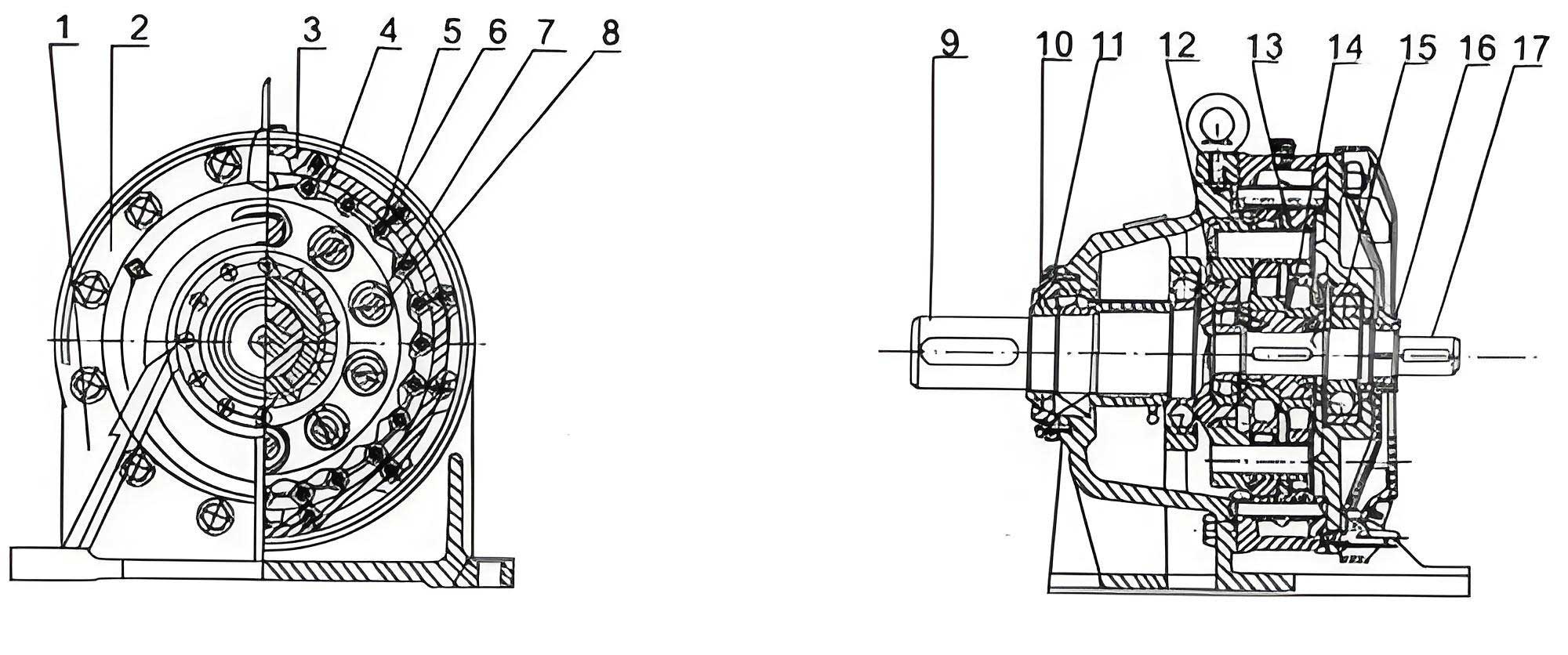
The core innovation of the cycloidal drive lies in its deviation from traditional involute gear systems. As I will explain, it belongs to the class of K-H-V (Kurzweil-Habenicht-Variator) planetary gear trains, specifically a type of少齿差 (small tooth difference) transmission. The fundamental motion is achieved through a hypocycloidal or, more precisely, a curtate epicycloidal curve generation. In a standard single-stage N-type cycloidal drive, the primary components include an input shaft, an eccentric cam or crank (forming the H mechanism with a rotating arm bearing), one or two cycloidal discs (also called planet wheels), and a stationary ring gear equipped with cylindrical pins, often sheathed with needle roller bearings to reduce friction. The cycloidal disc features tooth profiles generated from an epitrochoid curve, while the ring gear employs simple cylindrical pins as its teeth. The critical design parameter is the tooth difference; typically, the number of pins on the ring gear (Z_p) exceeds the number of lobes on the cycloidal disc (Z_c) by a small integer, usually 1. This tooth difference is the cornerstone of the high reduction ratio.
To mathematically describe the kinematics, let us define the following variables. Let the input speed (eccentric cam speed) be $n_{in}$ in revolutions per minute (RPM). The cycloidal disc undergoes a compound motion: it orbits around the center of the ring gear due to the eccentric input and simultaneously rotates about its own axis due to the constraint imposed by the meshing with the stationary pins. The reduction ratio $i$ for a single-stage cycloidal drive is given by:
$$ i = \frac{n_{in}}{n_{out}} = -\frac{Z_p}{Z_p – Z_c} $$
Since $Z_p – Z_c = 1$ in the most common configuration, the ratio simplifies to $i = -Z_p$. The negative sign indicates that the output rotation direction is opposite to the input direction. For instance, if a cycloidal drive uses a ring gear with 40 pins and a cycloidal disc with 39 lobes, the theoretical reduction ratio is 40:1. The output motion of the cycloidal disc is a slow, wobbling rotation. This motion is then converted into a concentric output shaft rotation through an output mechanism, typically a set of rollers (needle bearings) and slots or pins, often called a “cycloidal drive output unit” or “W-output机构”. This mechanism has a speed ratio of 1:1, transmitting only the pure rotation of the cycloidal disc while canceling its orbital eccentricity.
The tooth profile of the cycloidal disc is paramount for performance. It is derived from the path traced by a point on a generating circle rolling without slipping inside or outside a base circle. For the standard cycloidal drive, the curve is a curtate epitrochoid. The parametric equations for a point on the cycloidal disc lobe, relative to the disc’s center, can be expressed as:
$$ x = (R_p – R_r) \cos(\theta) + e \cos\left(\frac{Z_p}{Z_c} \theta\right) $$
$$ y = (R_p – R_r) \sin(\theta) – e \sin\left(\frac{Z_p}{Z_c} \theta\right) $$
Where:
- $R_p$ is the pitch circle radius of the pin ring.
- $R_r$ is the roller (pin sleeve) radius.
- $e$ is the eccentricity of the input cam.
- $\theta$ is the input rotation angle.
- $Z_p$ and $Z_c$ are as defined earlier.
This profile ensures multiple teeth are in contact simultaneously, often 50% or more of the pins are engaged, leading to exceptional load distribution and shock resistance—a hallmark of the cycloidal drive. The following table summarizes key geometrical relationships in a standard cycloidal drive design:
| Parameter | Symbol | Typical Relationship or Formula |
|---|---|---|
| Number of Ring Gear Pins | $Z_p$ | Typically 20 to 100+ |
| Number of Cycloidal Disc Lobes | $Z_c$ | $Z_c = Z_p – 1$ (for single tooth difference) |
| Eccentricity | $e$ | Design parameter, affects size and torque capacity |
| Pin Circle Radius | $R_p$ | Related to center distance: $a = e Z_p$ |
| Reduction Ratio | $i$ | $i = -Z_p / (Z_p – Z_c)$ |
| Transmission Efficiency | $\eta$ | Often 90-95% per stage due to rolling contact |
From my practical experience, the theoretical efficiency of a well-lubricated cycloidal drive can be estimated considering friction losses primarily in the rotating arm bearing and the needle bearings. A simplified model for mechanical efficiency $\eta$ might consider the torque loss due to friction:
$$ \eta \approx 1 – \frac{T_{loss}}{T_{in}} $$
Where $T_{loss}$ aggregates losses from bearing friction and sliding in the output mechanism. For a cycloidal drive operating under nominal load, this efficiency remains high, but it underscores the importance of lubrication, which I will address in detail later.
Moving beyond theory, the real-world performance of any cycloidal drive is inextricably linked to diligent maintenance. The compact and complex internal architecture of a cycloidal drive necessitates a proactive and informed approach to care. Neglect can rapidly degrade its advantages. In the following sections, I will dissect the maintenance regimen into four critical pillars: Operational Environment, Working State, Sealing Integrity, and Lubrication Management. Each pillar encompasses specific checks, procedures, and schedules that I have found essential for reliable operation.
Operational Environment
The cycloidal drive is designed for continuous duty in harsh conditions, but environmental limits must be respected. Based on my observations and manufacturer specifications, the ambient temperature for continuous operation should generally not exceed 40°C (104°F). At higher temperatures, the viscosity of lubricants can break down, and thermal expansion may alter clearances, leading to increased wear or even seizure. In applications such as furnace conveyors or outdoor equipment in hot climates, I recommend implementing active cooling measures. These can include forced air ventilation using fans, installing heat sinks or cooling fins on the housing, or employing thermal insulation plates to shield the cycloidal drive from radiant heat sources. Furthermore, the environment should be as free as possible from excessive dust, abrasive particles, moisture, and corrosive chemicals. If such contaminants are prevalent, additional protective enclosures or higher-grade sealing solutions for the cycloidal drive are mandatory. The table below provides a guideline for environmental adaptations:
| Environmental Factor | Acceptable Range (General) | Mitigation Strategy for Adverse Conditions |
|---|---|---|
| Ambient Temperature | -10°C to +40°C | For temperatures >40°C: Use cooling fans, heat sinks, or external cooling loops. For sub-zero starts, use low-temperature grease. |
| Relative Humidity | < 90% non-condensing | Use desiccants in enclosures, apply protective coatings, ensure breathers are functional. |
| Dust & Particulate Contamination | Minimal | Install additional seals (labyrinth, lip seals), use filtered breathers, implement positive pressure purge systems. |
| Chemical Exposure | None to mild | Select housing materials (e.g., stainless steel) and seals compatible with chemicals present. |
| Vibration & Shock | Within drive’s rated specifications | Ensure rigid mounting, use anti-vibration mounts if source is external, check balance of connected components. |
Working State and Mechanical Inspection
Regular monitoring of the cycloidal drive’s operational state is crucial. I advocate for a scheduled inspection routine that begins even before startup. First and foremost, the foundation and mounting of the cycloidal drive must be secure. All fastening bolts should be torqued to the manufacturer’s specification and checked periodically for loosening, especially after the initial run-in period. Misalignment between the cycloidal drive’s input/output shafts and the connected machinery (e.g., motor, pump, conveyor drum) is a primary cause of premature bearing failure and vibration. Alignment should be verified using dial indicators or laser alignment tools, ensuring parallel and angular misalignment are within tolerances (typically less than 0.05 mm and 0.05 degrees for precise applications).
During operation, listen for unusual noises such as grinding, knocking, or excessive whining. A healthy cycloidal drive operates with a relatively quiet, rhythmic hum. Use a stethoscope or vibration analysis equipment to detect early signs of bearing wear or tooth contact issues. Temperature monitoring is also vital; housing temperature can be monitored with infrared thermometers. A sudden temperature rise often indicates lubrication problems or overload.
Overloading is a silent killer of cycloidal drives. While they are renowned for high momentary overload capacity, sustained operation above the rated torque causes accelerated wear of the cycloidal disc lobes, needle pins, and especially the expensive rotating arm (eccentric) bearing. I emphasize that the rated torque of the cycloidal drive should be selected with a sufficient safety factor for the application. Implementing torque limiters or current sensing on the input motor can provide protection against prolonged overloads.
When disassembly becomes necessary, such as for replacing the rotating arm bearing, extreme care must be taken. The internal components of a cycloidal drive are precision-matched. Never apply impact force asymmetrically to the housing or shafts. Use proper pullers and presses. During reassembly, cleanliness is paramount. All sealing surfaces must be meticulously cleaned of old sealant and debris. Apply a fresh, appropriate-grade sealant (e.g., silicone RTV, anaerobic flange sealant) or install new gaskets. Before final closure, ensure all needle rollers and washers are correctly positioned. After assembly, manually rotate the input shaft to feel for any binding or uneven resistance—it should turn smoothly. Only after this verification should power be reapplied.
Sealing Integrity
The sealing system is the first line of defense for the cycloidal drive’s internal environment. The most critical seal is typically at the output shaft, where rotational motion occurs. Output shaft seals are consumable items subject to wear, hardening, and lip degradation over time. Failure of this seal leads to lubricant leakage, which starves internal components of oil, and allows ingress of contaminants. I recommend establishing a preventive replacement schedule for shaft seals based on operating hours or annually in severe environments. The choice of seal material (e.g., Nitrile, Viton, Polyurethane) should match the lubricant type and environmental exposure.
Static seals on housing joints and bearing covers also require attention during maintenance intervals. Inspect for signs of weeping or seepage. Breathers or vent plugs are often overlooked; they must be kept clean to prevent pressure buildup inside the cycloidal drive housing, which can force oil past seals. In dusty environments, use filtered breathers. The following checklist can be used for sealing system inspection:
| Component | Inspection Criteria | Action if Faulty |
|---|---|---|
| Output Shaft Seal | Check for visible leaks, grease wash-out, or dust accumulation on shaft near seal. Feel for shaft play. | Replace seal. Check shaft surface for wear or scoring; repair or replace if damaged. |
| Input Shaft Seal (if applicable) | Similar inspection as output seal. | Replace seal. |
| Housing Joints & Covers | Look for oil stains or seepage along mating flanges. | Disassemble, clean surfaces, reapply sealant or replace gasket. |
| Breather/Vent Plug | Ensure it is not clogged with dirt or paint. | Clean or replace. Upgrade to a filtered breather if needed. |
| Drain and Fill Plugs | Check sealing washer or O-ring for integrity. | Replace washer/O-ring during oil change. |
Lubrication Management
Proper lubrication is arguably the most critical aspect of cycloidal drive maintenance. The lubrication system must cater to two primary areas: the sliding/rolling contact between the cycloidal disc lobes and the needle pins, and the rotating arm bearing (a large needle roller bearing) which experiences high cyclic loads. An appropriate lubricant reduces friction, dissipates heat, and protects against wear and corrosion.
I always begin by adhering to the manufacturer’s recommendation for lubricant type (oil or grease) and viscosity grade. For oil-lubricated cycloidal drives, the oil level must be checked regularly via sight glasses or dipsticks. The drive should be stationary and level during checking. Under-lubrication leads to metal-to-metal contact and rapid failure. Overfilling can cause churning losses, overheating, and seal blow-out. For grease-lubricated units, the regreasing interval and quantity must be strictly followed. Over-greasing can generate excessive heat and damage seals.
The lubricant change interval is not fixed; it depends on duty cycle, temperature, and contamination. As a rule of thumb derived from industry practice and my own field data:
- After the initial break-in run (first 150-200 hours), change the oil/grease to remove wear-in particles.
- For continuous operation (24/7), change oil every 3-4 months.
- For single-shift operation (8 hours/day), change oil every 6-8 months.
- For intermittent, light-duty service, an annual change may suffice.
However, these are guidelines. Condition-based monitoring, such as oil analysis for viscosity, water content, and particle count, provides a more scientific approach to determining the optimal change interval for a cycloidal drive.
The process of changing lubricant must be executed cleanly. Before opening any ports, wipe the area around the fill and drain plugs. Use clean, dedicated tools. For oil changes, drain the old oil while the cycloidal drive is warm to facilitate better flow and removal of contaminants. Refill with the exact grade and quantity specified. For grease lubrication, purge out the old grease completely until fresh grease emerges from the relief port, avoiding mixing old and new grease. Here is a summary table for lubrication schedules:
| Operational Profile | Daily/Weekly Check | Oil Change Interval | Grease Replenishment Interval | Special Considerations |
|---|---|---|---|---|
| Continuous Heavy Duty (24/7, high load) | Check for leaks, noise, temperature daily. | Every 3 months or 2000 hours | N/A if oil-lubricated. For grease: Purge every 500-1000 hours. | Consider oil cooling or synthetic lubricants for high temperatures. |
| Intermittent Medium Duty (8-16 hrs/day) | Weekly checks sufficient. | Every 6-8 months or 3000 hours | Every 6 months or 1500 hours. | Monitor for condensation in oil. |
| Light Duty, Occasional Use | Monthly visual inspection. | Annually or per 1000 hours | Annually. | Ensure lubricant hasn’t separated or degraded during idle periods. |
| Harsh Environment (Dusty, Wet, Hot) | Daily checks mandatory. | Reduce interval by 30-50%. | Reduce interval by 30-50%. | Use sealed-for-life or special environment greases if applicable. |
Furthermore, the selection of lubricant can be guided by operating conditions. For low-speed, high-torque applications of the cycloidal drive, a lubricant with extreme pressure (EP) additives is beneficial. For wide temperature ranges, synthetic oils or greases offer better stability. The viscosity index (VI) should be high for applications with significant temperature variations. The required viscosity $\mu$ at operating temperature can be estimated based on the pitch line velocity and load, but generally, ISO VG 150-320 oils are common for industrial cycloidal drives.
A mathematical model for minimum oil film thickness $h_{min}$ in the rolling contacts, while simplified, underscores the importance of viscosity:
$$ h_{min} \propto (\mu_0 u)^{0.7} R^{0.43} / (E’^{0.03} w^{0.13}) $$
Where $\mu_0$ is the dynamic viscosity at operating temperature, $u$ is the entraining surface velocity, $R$ is the effective radius of curvature, $E’$ is the equivalent Young’s modulus, and $w$ is the load per unit width. Maintaining adequate film thickness is essential to prevent wear in the cycloidal drive’s critical meshing zones.
Advanced Considerations and Failure Analysis
In my research and troubleshooting experience, certain failure modes are recurrent in poorly maintained cycloidal drives. Pitting or spalling on the cycloidal disc lobes indicates surface fatigue due to overloading or insufficient lubrication. Flattening or brinelling of the needle pins suggests shock loads or misalignment. Excessive clearance or noise from the rotating arm bearing is often a result of contamination or lubricant breakdown. By understanding these failure signatures, maintenance can shift from time-based to condition-based, increasing the uptime and life of the cycloidal drive.
Another aspect is the dynamic behavior. While the cycloidal drive is inherently smooth due to multi-tooth engagement, torsional vibrations can be excited if the system’s natural frequency aligns with operating harmonics. The torsional stiffness $k_t$ of a cycloidal drive is high, contributing to a high natural frequency. An approximate formula for the system’s lowest torsional natural frequency $f_n$ is:
$$ f_n = \frac{1}{2\pi} \sqrt{\frac{k_t}{J_{load} + J_{drive}}} $$
Where $J_{load}$ and $J_{drive}$ are the inertias of the driven load and the cycloidal drive’s output side, respectively. Ensuring the operating speed and its harmonics do not coincide with $f_n$ helps avoid resonance issues.
In applications requiring ultra-precise positioning, such as robotic joints, backlash becomes a concern. The design of the cycloidal drive inherently minimizes backlash, but it can increase with wear. Regular inspection and, if designed for it, adjustment of the eccentric bearing preload or the output mechanism can help maintain low backlash levels.
To consolidate the maintenance philosophy, I propose an integrated approach. Use a digital log to record operating hours, environmental conditions, maintenance actions, and any observed anomalies for each cycloidal drive. This data trends performance and helps predict failures. Investing in simple predictive maintenance tools like infrared thermometers, vibration pens, and ultrasonic leak detectors pays dividends in preventing unexpected downtime.
Conclusion
The cycloidal drive is a masterpiece of mechanical engineering, offering a compelling blend of compactness, strength, and efficiency. However, its sophisticated internal geometry demands respect and conscientious care. Through this detailed exposition, I have endeavored to share insights from both theoretical foundations and practical field experience. The longevity and reliability of a cycloidal drive are not merely products of its design but are profoundly influenced by the rigor of its maintenance regimen. By systematically addressing the operational environment, mechanical state, sealing integrity, and lubrication—supported by periodic inspections and condition monitoring—users can ensure that their cycloidal drives operate at peak performance. This proactive approach mitigates the risk of catastrophic failure, reduces total cost of ownership, and ultimately allows the cycloidal drive to deliver on its promise of high torque density and durable service across countless industrial revolutions. The cycloidal drive, when properly maintained, remains an indispensable workhorse in the engineer’s arsenal for motion control.