
In the field of precision mechanical transmission, the cycloidal drive stands out for its high reduction ratio, compact design, and excellent load-sharing capabilities. However, achieving optimal performance in practical applications is heavily dependent on the precise control of tooth flank engagement clearances. These clearances are not merely manufacturing tolerances but are complex functions arising from a synthesis of machining errors, assembly misalignments, and inherent design principles. In this comprehensive study, I investigate the distribution laws of both tangential and normal engagement clearances within a cycloidal speed reducer. My analysis employs an analytical methodology to model the tooth profiles generated by form grinding—a relatively modern process—and to compute the resulting clearances when the drive is assembled with realistic component variations. The results fundamentally challenge the idealized assumption of multi-tooth contact, revealing that under no-load conditions, typically only one tooth pair is in contact. Furthermore, under load, especially when the cycloidal wheel is modified, the number of load-bearing teeth can be significantly less than half the theoretical number. This has profound implications for calculating the drive’s load capacity, stress distribution, and elastohydrodynamic lubrication analysis.
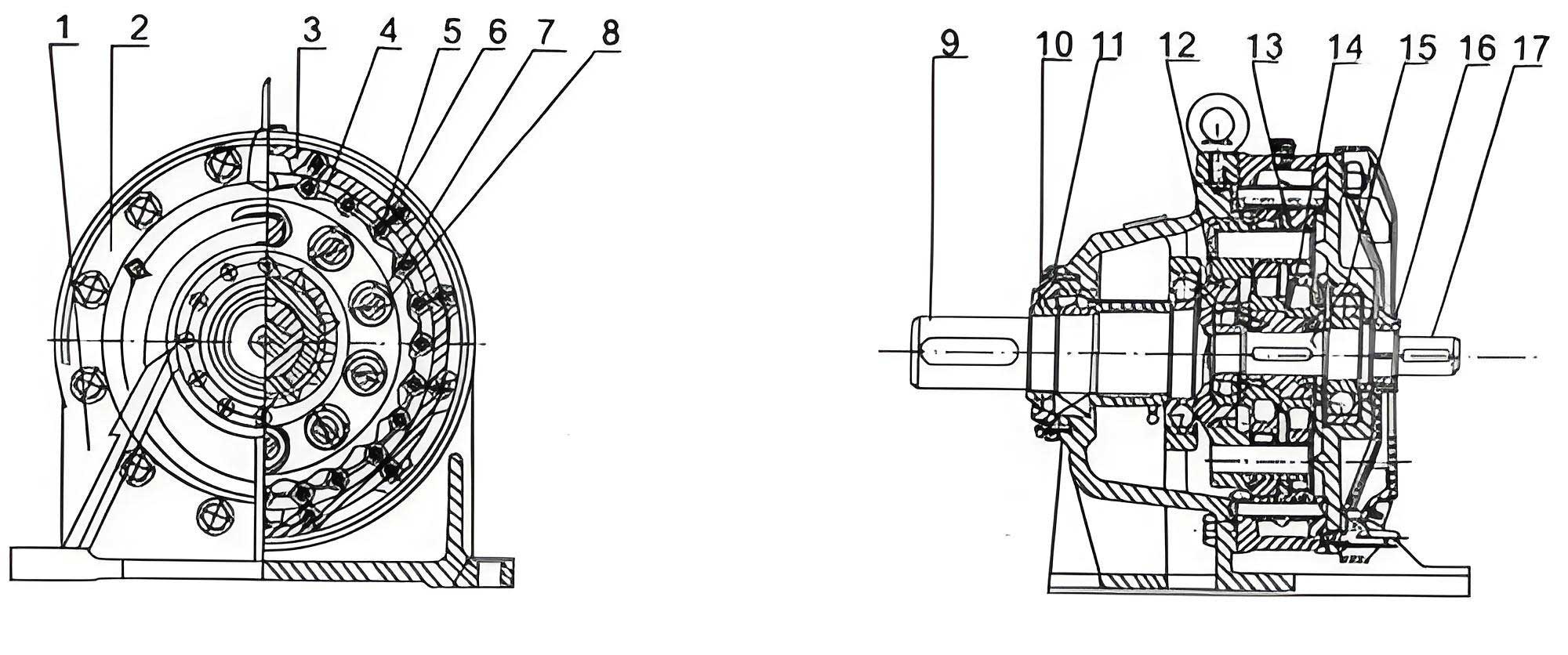
The core mechanism of a cycloidal drive involves a cycloidal disk (or wheel) meshing with a ring of cylindrical pins housed in a pin wheel. The motion is transmitted through an eccentric crank, resulting in a high speed reduction. The unique epitrochoidal shape of the cycloidal tooth is designed for conjugate action with the pins. However, in a real-world cycloidal drive, imperfections are inevitable. The tooth profiles on the cycloidal wheel are subject to machining inaccuracies; the pins and their housing have dimensional and positional variations; and the assembly of bearings, housings, and shafts introduces further eccentricities and misalignments. All these factors conspire to create a distribution of clearances between the cycloidal teeth and the pins when the drive is assembled. It is this clearance distribution, rather than a uniform theoretical contact, that determines the actual load-sharing behavior when torque is applied.
My investigation begins with the mathematical modeling of the cycloidal tooth profile as produced by form grinding. In this process, the grinding wheel is dressed to the exact theoretical shape of the cycloidal tooth. The workpiece (cycloidal wheel) is mounted on a machining arbor and indexed. The critical coordinates are established in a static frame \( (X_4, O_a, Y_4) \) attached to the machine. The theoretical profile of the grinding wheel, which replicates the desired cycloidal flank, is given by the following set of parametric equations. For a cycloidal drive with \( Z_a \) teeth on the cycloidal wheel and \( Z_b \) pins on the pin wheel, the coordinates are:
$$ X_4 = – R_Z \sin\left(\frac{\theta_b}{Z_a}\right) – \frac{K_1}{Z_b} \sin\left(\frac{Z_b}{Z_a}\theta_b\right) – \frac{r_Z \left[ K_1 \sin\left(\frac{Z_b}{Z_a}\theta_b\right) – \sin\left(\frac{\theta_b}{Z_a}\right) \right]}{\left[1 + K_1^2 – 2K_1 \cos\theta_b \right]^{1/2}} + \delta X_4 $$
$$ Y_4 = R_Z \cos\left(\frac{\theta_b}{Z_a}\right) – \frac{K_1}{Z_b} \cos\left(\frac{Z_b}{Z_a}\theta_b\right) + \frac{r_Z \left[ K_1 \cos\left(\frac{Z_b}{Z_a}\theta_b\right) – \cos\left(\frac{\theta_b}{Z_a}\right) \right]}{\left[1 + K_1^2 – 2K_1 \cos\theta_b \right]^{1/2}} + \delta Y_4 + \Delta Y_4(n) $$
Here, \( K_1 \) is the shortening coefficient, \( R_Z \) is the generating circle radius, \( r_Z \) is the pin radius (or grinding wheel equivalent), and \( \theta_b \) is the rolling angle parameter ranging from \(-\pi\) to \(\pi\). The terms \( \delta X_4 \) and \( \delta Y_4 \) represent dressing errors of the grinding wheel’s CNC system, while \( \Delta Y_4(n) \) is the feed error for the \(n\)-th tooth (\(n = 1\) to \(Z_a\)). Modifications such as negative offset or positive equidistant correction are applied by adjusting \( R_Z \) and \( r_Z \). After grinding, the actual tooth profile must be expressed in a coordinate system fixed to the cycloidal wheel’s theoretical center \( O’_{a1} \). Accounting for mounting eccentricity \( \Delta A \) with phase angle \( \varphi \), and arbor runout \( \Delta B \), the transformation yields the profile coordinates \( (X’_2, Y’_2) \):
$$ X’_2 = X_4 \cos\beta – Y_4 \sin\beta – \Delta A \cos\varphi – \Delta B $$
$$ Y’_2 = X_4 \sin\beta + Y_4 \cos\beta – \Delta A \sin\varphi $$
where \( \beta = \frac{2\pi}{Z_a}(n-1) + \beta_0 + \Delta\beta(n) \). The angle \( \beta_0 \) is an initial mounting angle, and \( \Delta\beta(n) \) is the indexing error of the grinding machine, obtainable through calibration. For mass-produced cycloidal drives, parameters like \( R_Z, r_Z, \delta X_4, \delta Y_4, \Delta Y_4(n), \Delta A, \varphi, \beta_0 \) become random variables within their tolerance bands.
The next stage of my analysis involves modeling the assembled cycloidal drive. In the converted mechanism (where the carrier is fixed), the centers of the pin wheel and the cycloidal wheel are not perfectly aligned due to assembly errors. Let \( O_b \) be the theoretical center of the input shaft, and \( O_a \) the center of the eccentric crank, with distance \( A’ \). The actual pin wheel center \( O’_b \) is offset from \( O_b \) by \( \Delta_2 \) at angle \( \alpha_2 \), due to bearing clearances and housing fit errors. Similarly, the actual cycloidal wheel center \( O’_{a1} \) is offset from \( O_a \) by \( \Delta_1 \) at angle \( \alpha_1 \), due to the clearance in the crank bearing. The actual pin radius (accounting for pin sleeve fit) is \( r’_Z \), and the pitch radius of the pin circle is \( R’_Z \). All these are treated as random variables. A static coordinate system \( (X’_4, O’_{a1}, Y’_4) \) is established, with \( O’_{a1}Y’_4 \) parallel to the crank vector \( \vec{O_a O_b} \).
To determine the engagement condition for any tooth pair, consider the \(n\)-th pin and the \(n\)-th cycloidal tooth. At a given input shaft rotation angle \( \theta_T \) in the converted mechanism, the pin has rotated from its initial position. The angle from the static axis to the center \( C’ \) of the \(n\)-th pin is:
$$ \theta’_b = (K-1) \cdot \frac{2\pi}{Z_b} + \delta_n – \theta_T $$
Here, \( K \) is the index number of the tooth counted from the static axis, and \( \delta_n \) is the tangential position error of that specific pin. The coordinates of the pin center \( C’ \) in the static frame are:
$$ X’_{C’4} = -R’_Z \sin\theta’_b – (\Delta_1 \cos\alpha_1 + \Delta_2 \cos\alpha_2) $$
$$ Y’_{C’4} = -R’_Z \cos\theta’_b – A’ + \Delta_1 \sin\alpha_1 – \Delta_2 \sin\alpha_2 $$
Meanwhile, a potential contact point \( E \) on the cycloidal tooth profile, defined by parameter \( \theta_b \) and transformed by the cycloidal wheel’s rotation angle \( \theta’_a \), has coordinates:
$$ X’_{E4} = X’_2 \cos\theta’_a + Y’_2 \sin\theta’_a $$
$$ Y’_{E4} = -X’_2 \sin\theta’_a + Y’_2 \cos\theta’_a $$
The condition for perfect contact (zero clearance) is that the distance \( C’E \) equals the pin radius \( r’_Z \). Therefore, for a given tooth pair (fixed \( K \)) and given \( \theta_T \), we solve the following equation for \( \theta_b \) and \( \theta’_a \):
$$ (X’_{C’4} – X’_{E4})^2 + (Y’_{C’4} – Y’_{E4})^2 = (r’_Z)^2 $$
This typically requires a two-dimensional numerical search around the theoretical contact positions. If a solution exists, it defines the exact kinematic position for that isolated pair. The deviation of the cycloidal wheel’s actual rotation from its theoretical position, when only that pair is meshing, is the tangential engagement error:
$$ \Delta\theta_N = \theta’_a – \frac{Z_b}{Z_a}\theta_T – \frac{J}{Z_a} 2\pi $$
where \( J \) indicates the number of cycloidal teeth to the right of the static axis. In a no-load cycloidal drive, only the tooth pair with the smallest absolute value of \( \Delta\theta_N \) will be in actual contact. For all other non-contacting tooth pairs, the tangential engagement clearance \( D_N \) is calculated as:
$$ D_N = \left( |\Delta\theta_N| – |\Delta\theta_N|_{min} \right) \frac{Z_a}{Z_b} R_Z $$
This tangential clearance is crucial for load distribution analysis because under load, the cycloidal wheel rotates as a whole, and only teeth with sufficiently small tangential clearances can come into contact and share the load.
Another metric is the normal engagement clearance \( D_F \), which is the shortest distance between the pin circle and the cycloidal tooth flank at a given assembly position. Once the contacting tooth pair (with rotation \( \theta’_{ac} \)) is identified, the normal clearance for any other pair is found by a one-dimensional search over \( \theta_b \):
$$ D_F = \min_{\theta_b} \left\{ \left[ (X’_{C’4} – X’_{E4})^2 + (Y’_{C’4} – Y’_{E4})^2 \right]^{1/2} – r’_Z \right\} $$
While informative, the normal clearance alone does not determine load-sharing; the tangential clearance, which incorporates the kinematic positioning, is the dominant factor in a cycloidal drive.
To illustrate the application of this analytical model, I conducted a detailed computational example for a common cycloidal drive configuration. The key parameters and their nominal versus realistic tolerance-affected values are summarized in the table below. This table encapsulates the myriad of factors influencing clearance in a real cycloidal drive.
| Parameter Symbol | Description | Nominal Value | Actual Value (With Tolerances) |
|---|---|---|---|
| \( Z_a \) | Number of cycloidal teeth | 25 | 25 (fixed) |
| \( Z_b \) | Number of pins | 26 | 26 (fixed) |
| \( K_1 \) | Shortening coefficient | 0.8 | 0.8 (fixed) |
| \( R_Z \) (Design) | Generating circle radius | 195.000 mm | 194.775 mm (modified) |
| \( r_Z \) (Design) | Pin/Grinding wheel radius | 13.500 mm | 13.875 mm (modified) |
| \( R’_Z \) | Actual pin circle radius | 195.000 mm | 195.000 ± 0.014 mm |
| \( r’_Z \) | Actual effective pin radius | 13.500 mm | 13.500 -0.025 mm |
| \( A’ \) | Eccentricity (crank arm) | 6.000 mm | 6.000 ± 0.020 mm |
| \( \Delta A \) | Workpiece mounting eccentricity | 0 mm | ± 0.0315 mm |
| \( \Delta B \) | Arbor radial runout | 0 mm | 0.005 mm |
| \( \delta X_4, \delta Y_4 \) | Grinding wheel dressing error | 0 mm | ± 0.002 mm |
| \( \Delta Y_4(n) \) | Wheel feed error | 0 mm | ± 0.010 mm |
| \( \Delta \beta(n) \) | Machine indexing error | 0 arcsec | ± 30 arcsec |
| \( \Delta_1 \) | Cycloidal wheel center offset | 0 mm | +0.0575 mm |
| \( \Delta_2 \) | Pin wheel center offset | 0 mm | +0.0173 mm |
| \( \delta_n \) | Pin tangential position error | 0 mm | ± 0.016 mm |
| \( \varphi \) | Phase of \( \Delta A \) | 0° | ±180° |
| \( \alpha_1 \) | Direction of \( \Delta_1 \) | 40° | 40.86° to 46.92° |
| \( \alpha_2 \) | Direction of \( \Delta_2 \) | 21.8° | 15.74° to 4.44° |
| \( \beta_0 \) | Initial mounting angle | 0° | ±180° |
Using a specific instance from the tolerance ranges (e.g., \( R’_Z = 195.014 \) mm, \( r’_Z = 13.475 \) mm, \( \Delta_1 = 0.0575 \) mm, \( \alpha_1 = 40^\circ \), etc.), I computed the engagement clearances over one full mesh cycle of the input shaft ( \( \theta_T \) from 0 to \( 2\pi/Z_b \) ). The results vividly demonstrate the clearance distribution. For a cycloidal drive with teeth generated by form grinding, the tangential clearance \( D_N \) for each potential contact pair (K=1 to Z_b/2) varies with input angle. In the unmodified case, the curves show that only one pair (in this instance, corresponding to K=5) maintains near-zero clearance across the cycle, confirming single-tooth contact under no-load. The other pairs exhibit significant tangential clearances, often exceeding 0.1 mm. When tooth profile modification (negative offset and positive equidistant) is applied, the pattern persists, but the magnitude of clearances for non-contacting teeth changes. The contacting pair might shift, and the clearances generally become larger for teeth farther from the contact zone.
For comparison, I also computed the clearances assuming the cycloidal wheel was generated by the traditional hobbling or generating grinding method. The equations differ slightly, as detailed in prior work, but the analytical framework remains similar. The results show a comparable single-tooth contact pattern, though the specific values and the identity of the contacting tooth pair (e.g., K=4) can differ. This underscores that the phenomenon is inherent to the assembly of imperfect components, not solely dependent on the machining method.
The normal clearance \( D_F \) distributions tell a complementary story. They are generally smaller in magnitude than the tangential clearances but follow a similar pattern: one tooth pair has essentially zero clearance, while others have a finite gap. The modification of the cycloidal tooth profile notably affects the shape and uniformity of the normal clearance distribution curve.
The implications of these findings for the design and analysis of cycloidal drives are substantial. First, it is unequivocal that the engagement clearance in a cycloidal drive is a synthesized outcome of all component errors and modifications. Designers must consider the entire system tolerance stack-up, not just individual part accuracy. Second, the distinction between tangential and normal clearance is critical. For load capacity calculation, the tangential clearance is the relevant parameter because it determines the kinematic “readiness” of a tooth to engage as the cycloidal wheel rotates under load deformation. A tooth might have a small normal gap but a large tangential offset, preventing it from bearing load until significant elastic torsion occurs.
Third, profile modification has a decisive impact on the number of teeth that will share the load. In my calculated example, for the theoretical 13 contacting pairs (since \( Z_b/2 = 13 \)), the unmodified profile could allow a larger proportion of teeth to potentially engage under load—perhaps 10 to 11 pairs if the maximum permissible tangential elastic deformation is around 0.2 mm. However, the modified profile, which is often applied to improve lubrication and reduce noise, results in a much harsher clearance distribution. In this case, only about 5 to 6 tooth pairs are within a 0.2 mm tangential clearance band and are likely to become load-bearing. This reduction must be accounted for in stress calculations, as the load per tooth will be higher. The performance of the cycloidal drive in terms of torque density, fatigue life, and transmission error is directly tied to this active tooth count.
Finally, regarding manufacturing processes, under the specific set of assumed tolerances and machine accuracies in this study, form grinding yielded slightly smaller engagement clearances compared to generating grinding. However, this is not a universal rule. The relative performance depends on the precision and error characteristics of each specific manufacturing system. A holistic analysis of the entire process chain is necessary to determine the optimal method for minimizing harmful clearances in a high-performance cycloidal drive.
In conclusion, my analytical investigation into tooth flank engagement clearance distribution provides a rigorous framework for understanding the real meshing behavior of cycloidal drives. By modeling the combined effects of form grinding errors, assembly misalignments, and intentional profile modifications, I have shown that the idealized multi-tooth contact is replaced by a single primary contact under no-load conditions. The load-sharing capability is governed by the distribution of tangential clearances, which can be severely affected by profile modification, potentially reducing the number of load-bearing teeth by more than half. This knowledge is indispensable for accurately predicting the static and dynamic performance, lifespan, and reliability of these compact and powerful precision drives. Future work should integrate this clearance model with finite element analysis for detailed stress computation and with elastohydrodynamic models to optimize lubrication design for cycloidal drives operating under various load conditions.