
In the realm of industrial material handling, belt conveyors stand as ubiquitous workhorses, facilitating the efficient transport of bulk goods across various sectors such as mining, agriculture, manufacturing, and logistics. The heart of any belt conveyor system is its drive mechanism, which dictates performance, reliability, and operational cost. Traditional drive configurations for belt conveyors have predominantly fallen into two categories. The first is the external drive assembly, comprising a separate electric motor, a reduction gearbox (often using involute gears), and a driving drum. This setup, while robust, demands significant footprint space, involves complex alignment procedures, and necessitates multiple mechanical couplings, leading to potential points of failure and increased maintenance. The second common approach is the oil-cooled electric drum, where the motor and reduction gearing are integrated within the hollow drum shell and immersed in oil for cooling and lubrication. Although compact, this design harbors critical flaws. The heat generated by the motor during operation accelerates the degradation of sealing elements at the interface between the motor housing and the rotating drum. This premature seal failure results in oil leakage or, worse, ingress of oil into the motor windings, causing insulation breakdown and eventual motor burnout. Furthermore, the involute gear systems typically employed in such drums offer a limited range of transmission ratios, exhibit relatively lower mechanical efficiency, and suffer from poor shock load capacity due to their single-tooth engagement characteristics, ultimately curtailing service life.
To fundamentally overcome these persistent limitations, we embarked on the development of a novel, advanced drive solution: the air-cooled cycloidal drive electric drum. This integrated unit represents a paradigm shift, merging a high-performance cycloidal drive speed reducer with a specially designed motor into a singular, compact drum assembly. The core innovation lies in the adoption of a cycloidal disc reduction mechanism, renowned for its exceptional durability, high torque density, and smooth power transmission. This article delves into the comprehensive design philosophy, operational principles, mechanical advantages, and application potential of this next-generation cycloidal drive electric drum, supported by detailed analytical models, comparative data, and performance specifications.
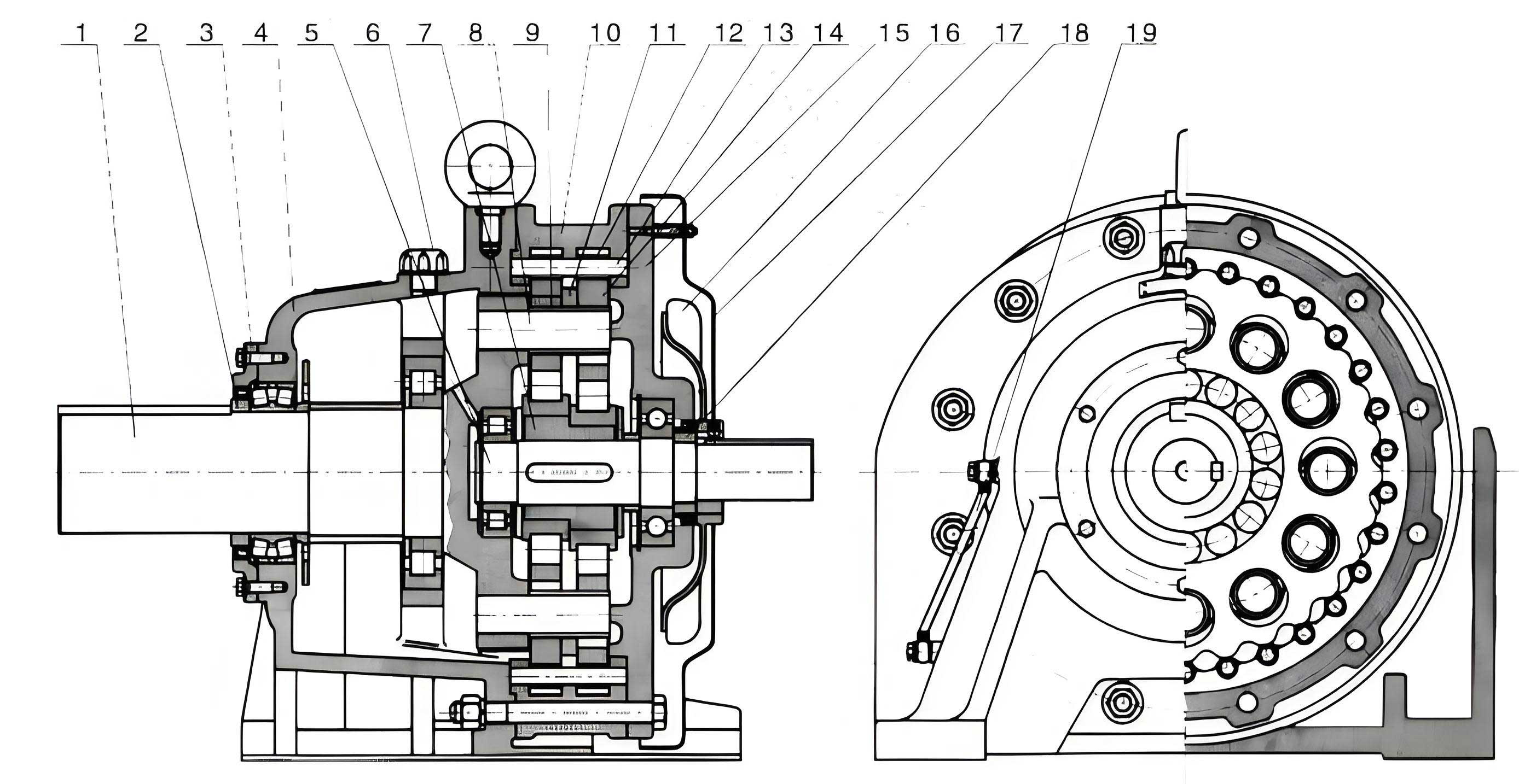
The architectural elegance and functional synergy of the cycloidal drive electric drum can be fully appreciated by examining its core components and their interaction. The assembly is characterized by a coaxial layout, ensuring compactness and direct power transmission. The primary subsystems are: the dedicated electric motor, the cycloidal drive speed reducer, the drum shell assembly, and the supporting bearing housings or foot mounts.
At the conceptual center is the cycloidal drive mechanism. Unlike conventional gear systems, a cycloidal drive operates on the principle of hypotrochoidal motion. It primarily consists of three key elements: an eccentric input cam (often part of the motor shaft), one or two cycloidal discs (also called lobed wheels or planet gears), and a stationary ring of cylindrical pins (the ring gear or stator). The motor, specifically engineered for this integrated application, features a stator frame rigidly connected to a non-rotating central shaft. The motor’s rotor is mounted on the eccentric portion of the high-speed input shaft. As the motor energizes, the rotor and the eccentric cam rotate. This eccentric motion imparts a complex orbiting and rotating movement to the cycloidal discs, which mesh with the fixed ring of pins. The geometry of the cycloidal disc’s lobes ensures that multiple pins are in contact simultaneously, distributing the load. The rotation of the cycloidal disc is slower than the input shaft’s rotation. This reduced rotation is extracted via a set of output pins or rollers and an output flange, which is directly keyed or bolted to the rotating drum shell. The supporting structure involves a fixed shaft (left side) that carries the motor housing and the outer casing of the cycloidal drive, forming a stationary assembly. The right-side shaft is the output member, rigidly connected to the drum and supported by bearings housed in mounting brackets.
The mathematical foundation of the cycloidal drive is fascinating and critical for understanding its performance advantages. The profile of a cycloidal disc is generated by a circle rolling inside another circle. The parametric equations defining the ideal cycloidal curve are given by:
$$ x(\theta) = (R_r – R_p) \cos(\theta) + e \cos\left(\frac{R_r – R_p}{R_p} \theta\right) $$
$$ y(\theta) = (R_r – R_p) \sin(\theta) – e \sin\left(\frac{R_r – R_p}{R_p} \theta\right) $$
Where:
\( R_r \) is the radius of the pin circle (ring gear pitch circle),
\( R_p \) is the radius of the rolling circle used to generate the lobe,
\( e \) is the eccentricity of the input cam,
\( \theta \) is the rotation angle of the generating circle.
The fundamental reduction ratio \( i \) of a standard cycloidal drive, a key metric, is determined by the difference between the number of pins on the stationary ring \( Z_p \) and the number of lobes on the cycloidal disc \( Z_c \). The formula is:
$$ i = -\frac{Z_p}{Z_p – Z_c} $$
Typically, \( Z_c = Z_p – 1 \), leading to a high reduction ratio \( i = Z_p \). The negative sign indicates direction reversal, which is often corrected by using two cycloidal discs phased 180° apart. For a single-stage cycloidal drive, ratios from 11:1 to 87:1, and even up to 119:1, are common and achievable in a remarkably compact space. The transmission ratio directly governs the output speed of the drum. The relationship between motor speed \( N_m \), reduction ratio \( i \), drum diameter \( D \), and belt linear speed \( V \) is:
$$ V = \frac{\pi D N_m}{60 i} $$
Where \( V \) is in m/s, \( D \) in meters, and \( N_m \) in RPM.
To elucidate the operational parameters and design flexibility offered by the cycloidal drive core, consider the following table detailing standard reduction ratios and their impact on drum speed for a common motor speed of 1440 RPM and a drum diameter of 0.32 m:
| Cycloidal Drive Ratio (i) | Output Speed (RPM) | Theoretical Belt Speed (m/s) | Application Suitability |
|---|---|---|---|
| 11 | 130.9 | 2.19 | High-speed conveying, light bulk |
| 17 | 84.7 | 1.42 | General purpose conveying |
| 29 | 49.7 | 0.83 | Moderate speed, medium duty |
| 59 | 24.4 | 0.41 | Slow speed, heavy-duty, inclined conveyors |
| 87 | 16.6 | 0.28 | Very low speed, precision feeding, heavy loads |
The inherent advantages of the cycloidal drive mechanism permeate every aspect of the electric drum’s performance, establishing it as a superior alternative. Below is a systematic exposition of its defining characteristics.
Extended Operational Speed Range: The cycloidal drive offers a wide spectrum of reduction ratios within a single-stage design. This allows the electric drum to achieve output speeds spanning from high velocity down to very slow creep speeds, with linear belt velocities easily reaching as low as 0.25 m/s or even less. This versatility eliminates the need for multi-stage gearboxes or external variable frequency drives for many applications. Furthermore, modifying the output speed does not necessitate replacing the entire drum unit. It can often be accomplished by simply exchanging the cycloidal disc and, in some cases, the pin ring—a modular feature that significantly reduces inventory costs and downtime. The relationship between desired speed and required cycloidal drive ratio can be precisely calculated using the formula provided earlier, enabling custom tailoring for specific processes.
Superior Load Distribution and Smooth Operation: The kinematics of the cycloidal drive ensure that at any given instant, approximately half of the pins in the ring are in contact with the lobes of the cycloidal disc. This multi-tooth simultaneous engagement is the cornerstone of its robustness. The contact stresses are distributed over a large surface area, leading to exceptional overload and shock load capacity. This makes the cycloidal drive electric drum exceptionally reliable for applications involving frequent starts and stops, jarring impacts from lumpy materials, or reversible operation. The motion transmission is inherently smoother and quieter compared to involute gear systems, which suffer from vibration and noise due to fewer teeth in contact and profile errors. The dynamic load capacity \( C_{dyn} \) can be modeled as a function of the number of engaging teeth \( n_e \), the material properties, and the force per tooth \( F_t \):
$$ C_{dyn} \propto n_e \cdot S_{ys} \cdot A_c $$
Where \( S_{ys} \) is the yield strength of the material and \( A_c \) is the effective contact area per tooth. For a cycloidal drive, \( n_e \) is high (often 6-10 or more), whereas for an involute gear pair, \( n_e \) is typically 1-2.
High Mechanical Efficiency: The rolling contact between the hardened cycloidal disc lobes and the cylindrical pins minimizes sliding friction. Primary losses are due to bearing friction on the eccentric cam and viscous drag in the lubricant. Consequently, the mechanical efficiency \( \eta_{cd} \) of a well-lubricated cycloidal drive is remarkably high, typically ranging from 90% to 97% per stage. This stands in contrast to many worm gear drives or complex multi-stage spur gear systems, which can have efficiencies as low as 50-80%. The overall drum efficiency \( \eta_{drum} \) combines the motor efficiency \( \eta_{motor} \) and the cycloidal drive efficiency:
$$ \eta_{drum} = \eta_{motor} \cdot \eta_{cd} $$
For a standard IE3 or IE4 efficiency class motor (η ~ 94-96%) coupled with a 95% efficient cycloidal drive, the overall efficiency can exceed 89-91%. This high efficiency translates directly into lower energy consumption, reduced heat generation, and smaller required motor ratings for the same output power, offering significant lifecycle cost savings. The following table compares key performance indicators between a traditional external drive and the cycloidal drive electric drum:
| Feature | Traditional External Drive (Motor+Gearbox) | Oil-cooled Involute Gear Drum | Air-cooled Cycloidal Drive Electric Drum |
|---|---|---|---|
| Transmission Principle | Involute Gears (e.g., helical, bevel) | Involute Gears | Cycloidal Drive |
| Footprint & Space | Large (separate components) | Compact | Very Compact (fully integrated) |
| Speed Range (Ratio Flexibility) | Moderate (requires gearbox changes) | Limited | Very Wide (11:1 to 87:1+) |
| Shock Load Capacity | Moderate (depends on gear design) | Poor (single-tooth engagement) | Excellent (multi-tooth engagement) |
| Transmission Efficiency | 85-95% (depends on stages) | 80-88% | 90-97% |
| Noise Level | Moderate to High | Moderate | Low |
| Maintenance Complexity | High (alignment, coupling wear) | High (seal failures, oil changes) | Low (sealed-for-life bearing, minimal seals) |
| Expected Service Life | Standard | Shorter (seal/gear wear issues) | 2-3 times longer |
| Cooling Method | External fan (motor), oil bath (gearbox) | Oil immersion (causes seal heat stress) | Air-cooled (natural convection/fan) |
Compact and Lightweight Design: The high torque-to-volume ratio of the cycloidal drive mechanism allows the entire reduction stage to be housed within the drum’s internal cavity without significantly increasing its diameter or length. This intrinsic compactness facilitates the creation of a streamlined, low-profile drum that can be easily installed in space-constrained environments. The mass of the cycloidal components is also lower than an equivalent rated involute gearset, contributing to a reduction in the rotational inertia of the drum, which benefits dynamic response during acceleration and deceleration. This design flexibility enables the production of a complete series of drums in various standard diameters (e.g., 200mm to 1000mm) and face widths to suit different belt widths and tension requirements. Furthermore, the entire assembly can be encased in a sealed housing, creating a totally enclosed, fan-cooled (TEFC) or even a completely enclosed non-ventilated (CENV) unit that is impervious to dust, moisture, and corrosive atmospheres, making it ideal for harsh industrial and outdoor settings.
Extended Service Life and Reliability: The dominant wear mechanism in the cycloidal drive is rolling contact fatigue, which progresses much slower than the abrasive and pitting wear common in sliding-contact gear systems. The use of high-carbon chromium bearing steel, heat-treated to high hardness (60-62 HRC), for both the discs and pins ensures exceptional wear resistance. The absence of an oil bath surrounding the motor eliminates the primary failure mode of seal degradation and oil ingress. Instead, the cycloidal drive compartment is lubricated with a moderate amount of high-quality grease or oil, sufficient for the rolling elements but isolated from the motor windings. The motor is cooled by ambient air flowing over its external fins or by an integrated external fan, preventing thermal stress on critical seals. This separation of functions dramatically enhances reliability. Empirical data and field tests indicate that the service life of a cycloidal drive electric drum, under comparable operating conditions, can be 2 to 3 times longer than that of a conventional oil-cooled involute gear drum. The mean time between failures (MTBF) is substantially increased, reducing total cost of ownership.
The selection and engineering of a cycloidal drive electric drum for a specific application involve a detailed analysis of several interrelated parameters. A systematic design approach must account for the required belt pull (effective tension), belt speed, drum diameter, installed power, and environmental conditions. The core calculation starts with determining the drum’s shaft torque \( T \) requirement:
$$ T = F_e \cdot \frac{D}{2} $$
Where \( F_e \) is the effective tension in the belt (N). The required motor power \( P_m \) is then:
$$ P_m = \frac{F_e \cdot V}{1000 \cdot \eta_{drum}} \quad \text{(kW)} $$
or $$ P_m = \frac{T \cdot \omega_{out}}{1000 \cdot \eta_{drum}} = \frac{T \cdot 2 \pi N_{out}}{60000 \cdot \eta_{drum}} \quad \text{(kW)} $$
Where \( \omega_{out} \) is the output angular velocity in rad/s and \( N_{out} \) is the output speed in RPM. Once \( P_m \) and \( N_{out} \) (or \( V \) and \( D \)) are known, the necessary cycloidal drive reduction ratio \( i \) can be selected from the standard range to match the motor’s synchronous speed (e.g., 1500 RPM or 1000 RPM for 50Hz supply). The torque capacity of the selected cycloidal drive must exceed the calculated shaft torque with an appropriate service factor \( S_f \) accounting for shock loads and duty cycle:
$$ T_{rated\ drive} \geq T \cdot S_f $$
Typical service factors for conveyor applications range from 1.2 to 1.8. The physical integration also requires careful thermal management. The heat dissipation \( Q_{gen} \) from losses must be balanced by the cooling capacity. For an air-cooled drum, the heat generated is primarily from motor losses \( P_{loss,m} \) and drive losses \( P_{loss,cd} \):
$$ Q_{gen} = P_{loss,m} + P_{loss,cd} = P_m \left( \frac{1}{\eta_{motor}} – 1 \right) + (P_m \cdot \eta_{motor}) \left( \frac{1}{\eta_{cd}} – 1 \right) $$
This heat is dissipated via convection and radiation from the drum surface area \( A_s \). A simplified steady-state heat balance can be expressed as:
$$ Q_{gen} = h \cdot A_s \cdot (T_{surface} – T_{ambient}) $$
Where \( h \) is the combined heat transfer coefficient. Ensuring \( T_{surface} \) remains within safe limits for motor insulation class (e.g., Class F, 155°C) is critical for reliable operation.
The application spectrum for the cycloidal drive electric drum is vast. Its robustness suits heavy-duty industries like mining (for ore and coal conveyors), ports (ship loaders and unloaders), and steel plants. Its precise speed control down to very low ranges makes it ideal for feeding applications in packaging, food processing, and chemical dosing systems. The enclosed design is perfect for washdown environments in the pharmaceutical and food & beverage industries. The modularity of the cycloidal drive allows for easy field retrofitting onto existing conveyor frames, upgrading performance and reliability without major structural modifications.
In conclusion, the integration of a cycloidal drive mechanism into an electric drum represents a significant technological advancement for belt conveyor drives. By directly addressing the shortcomings of traditional systems—through multi-tooth engagement for durability, high efficiency for energy savings, a wide speed ratio range for flexibility, and a sealed air-cooled design for reliability—the cycloidal drive electric drum delivers a compelling value proposition. Its compact, integrated form factor simplifies installation and maintenance, while its extended service life reduces the total cost of ownership. As industries continue to strive for higher efficiency, reliability, and automation, the adoption of advanced drive solutions like the cycloidal drive electric drum is poised to become the new standard for modern material handling systems. The underlying principles of the cycloidal drive, rooted in elegant mathematics and precision engineering, ensure that this technology will remain at the forefront of power transmission innovation for years to come.