
In the field of precision power transmission, cycloidal drives, also known as cycloidal pinwheel reducers, are widely recognized for their high torque density, compact design, and excellent efficiency. These drives are commonly employed in robotics, industrial machinery, and aerospace applications where reliable speed reduction is critical. However, during my extensive involvement in designing and manufacturing these reducers, I have consistently observed a persistent issue: the unequal distribution of transmitted power between the left and right cycloidal gears in the standard W-mechanism with pin-slot output. This imbalance not only leads to uneven wear on components, such as pin sleeves, but also limits the overall torque capacity and operational lifespan of the drive, particularly in high-power applications. This article aims to delve deeply into this problem from a theoretical standpoint, establish a comprehensive analytical framework, and propose practical design enhancements to mitigate the imbalance, thereby unlocking the full potential of cycloidal drive systems.
The core of the cycloidal drive’s operation lies in its unique kinematic principle. A high-speed input shaft rotates an eccentric cam, which drives a pair of cycloidal gears—often referred to as the left and right gears—in a planetary motion against a stationary ring of pin teeth. This motion is then converted into a low-speed rotation of the output shaft via an output mechanism. The most prevalent output mechanism is the pin-slot or W-mechanism, where a set of pins (or rollers) attached to the output shaft engages with corresponding holes (slots) in the cycloidal gears. While theoretically elegant, this configuration, when implemented with a cantilevered pin structure, introduces a significant mechanical asymmetry that results in the left cycloidal gear bearing the brunt of the load. The right gear, though essential for dynamic balance and constraint, contributes minimally to torque transmission under standard designs. This inherent flaw has been a known yet under-analyzed challenge in the industry.
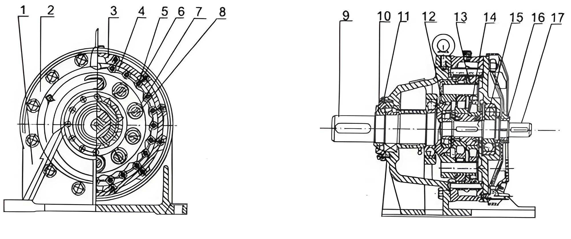
To quantify this power transmission imbalance, a fundamental re-examination of the pin-slot W-mechanism is necessary. In a typical cycloidal drive, the pins are fixed at one end (near the output side) and extend cantilever-style through the cycloidal gears. The left cycloidal gear is positioned closer to the fixed base of the pins, while the right gear is located near the free end. If the pins were perfectly rigid, the force exerted by each gear on the pins would be equal, leading to balanced torque sharing. However, in reality, the pins exhibit both bending and shear deformation under load. This deformation causes a relative displacement between the pin and the gear holes, altering the force distribution. The key insight is that the deformation pattern of the cantilevered pin forces the left gear to carry most of the load, as it must deform the pin at a point of higher stiffness, while the right gear acts on a more compliant section. A preliminary simplified estimate, considering only bending and assuming each gear drives only its adjacent pin segment, reveals a dramatic disparity. For instance, with typical arm lengths L1 (left) and L2 (right), the force ratio can be as high as $(L2/L1)^3$, indicating that the right gear’s contribution might be negligible. This underscores the critical need for a detailed elastomechanical analysis of the pin under combined loading from both gears.
The foundation of our analysis is the modeling of pin deformation under the action of forces from both cycloidal gears. We define the left cycloidal gear as the one adjacent to the output shaft (fixed end of pins), and the right gear as the one near the input side. The pins are analyzed as elastic beams subjected to concentrated forces. Three key forces are identified: $Q_L$ from the left gear acting at point L (distance L1 from fixed end), $Q_R$ from the right gear acting at point R (distance L2 from fixed end), and an interaction force $Q_{RL}$ that arises because the left pin’s deformation at point R is constrained by the hole in the right gear. The total output torque $M_v$ is the resultant of these forces acting on the pin circle. The deformation of the pin, comprising both bending and shear components, must satisfy compatibility conditions at points L and R. The following table summarizes the key geometric and material parameters used in the analysis for a cycloidal drive.
| Parameter | Symbol | Description |
|---|---|---|
| Number of Pins | $Z_w$ | Total pins in the output mechanism. |
| Pin Circle Radius | $R_w$ | Radius of the circle on which pin centers lie on the cycloidal gear. |
| Pin Diameter | $d_w$ | Diameter of the load-carrying pins. |
| Left Arm Length | $L_1$ | Distance from pin fixed end to left gear force point. |
| Right Arm Length | $L_2$ | Distance from pin fixed end to right gear force point. |
| Total Pin Length | $L_3$ | Overall cantilever length of the pin. |
| Young’s Modulus | $E$ | Elastic modulus of pin material. |
| Shear Modulus | $G$ | Shear modulus of pin material. |
| Area Moment of Inertia | $J$ | $J = \frac{\pi}{64}d_w^4$ for a solid circular pin. |
| Cross-sectional Area | $F$ | $F = \frac{\pi}{4}d_w^2$ for a solid circular pin. |
| Output Torque | $M_v$ | Design output torque of the cycloidal drive. |
The bending deformation is calculated using the principle of superposition and Mohr’s theorem. For the right pin, subjected only to force $Q_R$ at point R, the bending deflections at points L, R, and J (the free end) are derived. The flexibility coefficients $\lambda_{ij}$ represent the deflection at point i due to a unit force at point j. For bending:
$$ \lambda_{11} = \frac{L_1^3}{3EJ}, \quad \lambda_{12} = \lambda_{21} = \frac{1}{3EJ}\left(\frac{3}{2}L_1^2 L_2 – \frac{1}{2}L_1^3\right), \quad \lambda_{22} = \frac{L_2^3}{3EJ}, \quad \lambda_{32} = \frac{1}{3EJ}\left(\frac{3}{2}L_2^2 L_3 – \frac{1}{2}L_2^3\right) $$
For the left pin, subjected to both $Q_L$ and $Q_{RL}$, the total bending deflections are obtained by superposition. Simultaneously, shear deformation is considered by assuming a uniform shear stress distribution across the pin section for simplicity. The shear deflection at a point distance $x$ from the fixed end due to a force $Q$ is given by $f_{shear} = \frac{Q x}{GF}$, where $G$ is the shear modulus and $F$ is the cross-sectional area. Defining coefficients $t_1 = \frac{L_1}{GF}$ and $t_2 = \frac{L_2}{GF}$, the total deflections (bending + shear) at critical points can be expressed. For the right pin, the total deflections at L and R are:
$$ f_{RL} = (\lambda_{12} + t_1)Q_R, \quad f_{RR} = (\lambda_{22} + t_2)Q_R $$
For the left pin, the total deflections at L and R are:
$$ f_{LL} = (\lambda_{11} + t_1)Q_L – (\lambda_{12} + t_1)Q_{RL}, \quad f_{LR} = (\lambda_{12} + t_1)Q_L – (\lambda_{22} + t_2)Q_{RL} $$
The deformation compatibility conditions require that: 1) The deflection of the left pin at point L equals its deflection at point R ($f_{LL} = f_{LR}$), as it is a rigid body in itself. 2) The deflection of the right pin at point R equals the deflection of the left pin at point R ($f_{RR} = f_{LR}$), as both are connected through the right cycloidal gear’s hole. These provide two equations. The third equation comes from the equilibrium of torque: the sum of the forces $Q_L$, $Q_{RL}$, and $Q_R$ must generate the total output torque $M_v$. From standard cycloidal drive theory, the maximum force on a pin is related to torque by $Q_{max} = \frac{4M_v}{Z_w R_w}$. Since the three forces collectively act to produce the output, we have:
$$ Q_L + Q_{RL} + Q_R = C = \frac{4M_v}{Z_w R_w} $$
Solving these three simultaneous equations yields expressions for the three forces. After algebraic manipulation, we obtain:
$$ a = \frac{\lambda_{22} – \lambda_{12} – t_1 + t_2}{\lambda_{12} – \lambda_{11}}, \quad b = \frac{\lambda_{22} + t_2}{\lambda_{12} + \lambda_{22} + t_1 + t_2} $$
$$ Q_L = bC, \quad Q_{RL} = \frac{b}{a} C, \quad Q_R = C – Q_L – Q_{RL} $$
The torque transmitted by the left cycloidal gear $M_L$ and the right cycloidal gear $M_R$ can then be calculated:
$$ M_L = \frac{Z_w R_w}{4} Q_L, \quad M_R = \frac{Z_w R_w}{4} (Q_{RL} + Q_R) $$
The power transmission imbalance ratio is a critical metric:
$$ \text{Imbalance Ratio} = \frac{M_L}{M_R} = \frac{Q_L}{Q_{RL} + Q_R} $$
This ratio clearly demonstrates the extent to which one cycloidal gear dominates the load-sharing in the drive. Furthermore, the percentage of total torque carried by each gear is:
$$ \text{Left Gear Share} = \frac{Q_L}{C} \times 100\%, \quad \text{Right Gear Share} = \frac{Q_{RL} + Q_R}{C} \times 100\% $$
To validate this theoretical model, I applied it to a specific industrial cycloidal drive design with the following parameters: maximum power $P_{max} = 37 \text{ kW}$, efficiency $\eta = 0.9$, total ratio $i = 59$, input speed $n_e = 1000 \text{ rpm}$, $Z_w = 10$, $d_w = 40 \text{ mm}$, $R_w = 150 \text{ mm}$, $L_1 = 18 \text{ mm}$, $L_2 = 73 \text{ mm}$, $L_3 = 105 \text{ mm}$, $E = 2.1 \times 10^5 \text{ MPa}$, and $G = 8.02 \times 10^4 \text{ MPa}$. The calculated output torque $M_v$ from Equation (22) is:
$$ M_v = 9550 \cdot \eta \cdot i \cdot \frac{P_{max}}{n_e} = 9550 \times 0.9 \times 59 \times \frac{37}{1000} \approx 18700 \text{ N·m} $$
$$ C = \frac{4M_v}{Z_w R_w} = \frac{4 \times 18700}{10 \times 0.15} \approx 50000 \text{ N} $$
Computing the coefficients and forces:
$$ J = \frac{\pi}{64} \times (0.04)^4 \approx 1.2566 \times 10^{-7} \text{ m}^4, \quad F = \frac{\pi}{4} \times (0.04)^2 \approx 1.2566 \times 10^{-3} \text{ m}^2 $$
$$ \lambda_{11} \approx 1.23 \times 10^{-9} \text{ m/N}, \quad \lambda_{12} \approx 1.45 \times 10^{-8} \text{ m/N}, \quad \lambda_{22} \approx 8.45 \times 10^{-7} \text{ m/N} $$
$$ t_1 \approx 1.78 \times 10^{-10} \text{ m/N}, \quad t_2 \approx 7.23 \times 10^{-10} \text{ m/N} $$
$$ a \approx 13.94, \quad b \approx 0.923 $$
$$ Q_L \approx 46150 \text{ N}, \quad Q_{RL} \approx 3310 \text{ N}, \quad Q_R \approx 540 \text{ N} $$
The resulting torques and imbalance are:
$$ M_L \approx 17300 \text{ N·m}, \quad M_R \approx 1440 \text{ N·m} $$
$$ \text{Imbalance Ratio} = \frac{17300}{1440} \approx 12.0 $$
$$ \text{Left Gear Share} \approx 92.3\%, \quad \text{Right Gear Share} \approx 7.7\% $$
This calculation confirms a severe power transmission imbalance, with the left cycloidal gear carrying over 92% of the load. The deformation $S$ at the output, calculated from the deflection formulas, is approximately 0.052 mm, which is consistent across the compatibility points. Such imbalance inevitably leads to accelerated wear on the left pin sleeves and bearings, reducing the drive’s reliability and effective torque capacity. This quantitative insight provides a strong basis for redesign efforts aimed at improving the performance of cycloidal drives.
To address this fundamental flaw in the cycloidal drive, several design modifications can be explored. The primary goal is to redistribute the load more evenly between the two cycloidal gears without drastically altering the overall dimensions of the reducer. One effective approach is to introduce a load-equalizing ring at the free end of the pins. This ring mechanically links all pins together at their right ends (near the input side), effectively creating a much stiffer elastic support for the cantilevered pins. This transforms the pin’s boundary condition from a pure cantilever to a beam fixed at one end and supported by a high-stiffness elastic foundation at the other, significantly reducing the deflection disparity between points L and R. The equalizing ring forces the pins to share loads more collectively, thereby allowing the right cycloidal gear to engage more effectively. In practice, this modification has shown promising results in prototype testing, where the drive exhibited reduced wear patterns and lower operating temperatures even under increased torque loads.
Another theoretical avenue involves intentionally introducing a controlled clearance or compliance mismatch. For instance, one could design the pin sleeves or the gear holes with slightly different diameters. By making the left gear’s engagement have a small radial clearance that must be taken up before full load transfer, the initial load can be shifted toward the right gear. However, such approaches require careful dynamic analysis to avoid introducing backlash, vibration, or impact noise during start-up or torque reversals. A more integrated solution might involve optimizing the pin geometry itself, using tapered or stepped pins to tailor the bending stiffness along the length, thereby balancing the deformation under load. These strategies all aim to modify the flexibility coefficients $\lambda_{ij}$ and $t_i$ in our equations to achieve a more favorable force distribution.
The implications of solving this imbalance extend beyond mere durability. For high-performance cycloidal drives used in precision applications like robotic joints or satellite positioning systems, even torque distribution is crucial for smooth operation, minimal backlash, and high positional accuracy. By ensuring both cycloidal gears contribute significantly to power transmission, the overall stress on components is lowered, allowing for either a more compact design for the same torque rating or a higher torque capacity for the same envelope size. This enhances the competitiveness of cycloidal drives against other speed reducer technologies like harmonic drives or planetary gear sets.
In conclusion, this research provides a rigorous theoretical framework for analyzing and quantifying the power transmission imbalance inherent in standard cycloidal drive designs with cantilevered pin output mechanisms. The developed mathematical model, incorporating both bending and shear deformations, successfully predicts the severe load bias toward the left cycloidal gear, as confirmed by a detailed numerical example. The proposed methodology serves as a valuable tool for designers to evaluate and optimize key parameters such as pin diameters, arm lengths, and material properties. Furthermore, the suggested design improvements, particularly the implementation of a load-equalizing ring, offer a practical path toward mitigating this imbalance. Future work should include experimental validation through instrumented testing to directly measure torque sharing between gears under various operating conditions. Additionally, advanced finite element analysis could be employed to refine the model by considering factors like contact stresses, bearing clearances, and thermal effects. Ultimately, addressing this imbalance is essential for advancing the reliability, efficiency, and power density of cycloidal drives, ensuring they continue to meet the demanding requirements of modern mechanical systems.