
In the realm of precision machinery and robotics, the cycloidal drive stands out as a critical component for high-torque, low-backlash applications, particularly in robotic joints. My research focuses on exploring innovative design approaches for cycloidal drives, specifically those with large eccentricity values, to enhance transmission accuracy and reduce backlash. Traditional cycloidal drives typically operate with eccentricities that adhere to the constraint $E < R_1 / N$, where $E$ is the eccentricity, $R_1$ is the pitch circle radius of the pin gears, and $N$ is the number of pins. However, by pushing beyond this conventional boundary to large eccentricities where $E > R_1 / N$, I aim to investigate how such modifications impact geometric modeling, manufacturing processes, and overall transmission performance. This article delves into the methodologies for designing cycloidal gears with large eccentricities, utilizing cutting simulation techniques for profile generation, and employing multi-body dynamics simulations to analyze transmission errors. The goal is to provide insights that could lead to more stable and precise cycloidal drive systems, thereby contributing to advancements in high-precision reducers like the RV reducer commonly used in industrial robots.
The cycloidal drive mechanism, often referred to as a cycloidal speed reducer, relies on the meshing between a cycloidal gear and a set of pin gears to achieve high reduction ratios with minimal vibration. In my work, I prioritize understanding the fundamental principles that govern the cycloidal drive’s operation, especially when eccentricity is increased beyond traditional limits. The geometric design of the cycloidal gear tooth profile is paramount, as it directly influences contact patterns, load distribution, and transmission errors. For a conventional cycloidal drive with normal eccentricity, the tooth profile coordinates $(x, y)$ can be derived from the following parametric equations, which account for the rolling motion of the generating circle:
$$x = R_1 \cos t – R_p \left[ \cos \left( t + \arctan \frac{\sin[(1-N)t]}{R_1/N – \sin[(1-N)t]} \right) \right] – E \cos(Nt)$$
$$y = -R_1 \sin t + R_p \sin \left( t + \cos \left( t + \arctan \frac{\sin[(1-N)t]}{R_1/N – \sin[(1-N)t]} \right) \right) + E \sin(Nt)$$
Here, $R_p$ represents the pin radius, $t$ is the contact angle ranging from $0^\circ$ to $360^\circ$, and other parameters are as defined earlier. These equations yield the equidistant curve of an elongated epicycloid, which forms the basis for the cycloidal gear teeth in standard designs. However, when dealing with a large eccentricity cycloidal drive, these equations become inadequate because the condition $E > R_1 / N$ leads to geometric constraints that prevent direct application. Instead, I adopt a cutting simulation method to generate the tooth profile. This approach involves modeling the motion of a milling cutter with a radius equal to $R_p$ along a toolpath trajectory defined by modified equations. The trajectory coordinates $(x, y)$ for the cutter are given by:
$$x = R_p N \cos t – E \cos(Nt)$$
$$y = R_p N \sin t – E \sin(Nt)$$
By simulating this toolpath over a full cycle of $t$, I can virtually machine a blank to produce the cycloidal gear tooth profile. This method ensures accurate profile generation for large eccentricity cycloidal drives, allowing for precise control over tooth geometry. To illustrate the differences, I developed geometric models for various eccentricity values using CAD software and AutoLISP scripting, which facilitated the visualization of tooth contours. The resulting profiles show that as eccentricity increases, the tooth thickness decreases, potentially affecting strength, but this trade-off is evaluated in the context of improved transmission performance. For clarity, Table 1 summarizes the key design parameters used in my analysis for the cycloidal drive, highlighting the range of eccentricities considered.
| Parameter | Symbol | Value |
|---|---|---|
| Number of Cycloidal Gear Teeth | $Z_c$ | 35 |
| Number of Pin Gears | $N$ | 36 |
| Pin Pitch Circle Radius | $R_1$ | 90 mm |
| Pin Radius | $R_p$ | 5 mm |
| Eccentricity | $E$ | 1.75 mm, 3 mm, 4 mm |
| Critical Eccentricity | $R_1 / N$ | 2.5 mm |
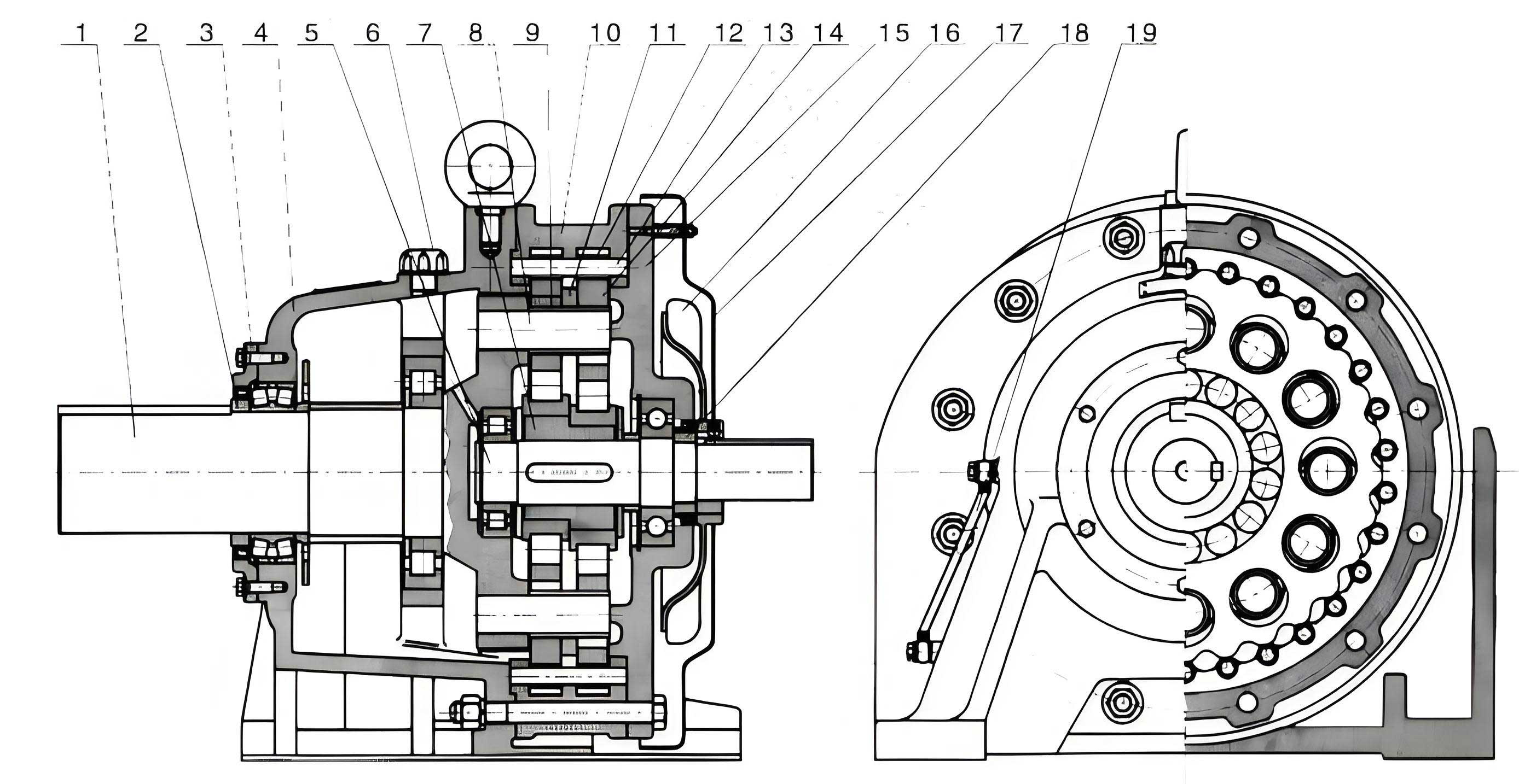
Transitioning from geometric modeling to performance analysis, I focus on evaluating the transmission errors of a cycloidal drive integrated into an RV reducer configuration. The RV reducer, which incorporates a cycloidal drive as its second stage, is renowned for its compactness and high precision in robotic applications. To assess the impact of large eccentricity on transmission performance, I constructed a virtual prototype model using MSC ADAMS, a multi-body dynamics simulation software. This model includes key components such as the input sun gear, planetary gears, cycloidal gears with large eccentricity, pin gear housing, and output disk. I defined appropriate joints and constraints: fixed joints for stationary parts like the housing, revolute joints for rotating elements, and contact forces to simulate meshing interactions between gears and pins. For the cycloidal drive meshing, I applied contact forces between the cycloidal gear teeth and the pins, capturing the multi-point contact characteristic inherent to cycloidal drives.
In the simulation, I imposed a constant input speed of 400 rpm on the sun gear, using a STEP function to gradually ramp up from 0 to 400 rpm over 0.2 seconds to avoid convergence issues. A constant output torque of 423 N·m was applied in the opposite direction to simulate load conditions, also implemented via a STEP function. The transmission error, denoted as $\theta_{error}$, is calculated as the difference between the actual output rotation $\theta_2$ and the ideal output rotation based on the reduction ratio, defined as $\theta_{error} = \theta_2 – \theta_1 / i$, where $i$ is the gear ratio. To quantify performance, I derived several error metrics: the average error $\bar{\theta}_{error}$, the average absolute error $|\bar{\theta}_{error}|$, and the maximum absolute error $|\theta_{error}|_{max}$. These are computed using the formulas:
$$\bar{\theta}_{error} = \frac{1}{n} \sum_{k=1}^{n} \theta_{error}(k)$$
$$|\bar{\theta}_{error}| = \frac{1}{n} \sum_{k=1}^{n} |\theta_{error}(k)|$$
$$|\theta_{error}|_{max} = \max(|\theta_{error}(k)|)$$
where $n$ is the number of sampling points during simulation. My simulations covered three eccentricity cases: a normal eccentricity of 1.75 mm (below the critical value) and large eccentricities of 3 mm and 4 mm (above the critical value). The results, plotted over time, reveal significant insights into the behavior of cycloidal drives under varying eccentricities. For the normal eccentricity cycloidal drive, the transmission error exhibits relatively larger fluctuations, indicating higher vibration and potential backlash. In contrast, for large eccentricity cycloidal drives, the error curves show reduced amplitude oscillations, suggesting smoother operation. Specifically, as eccentricity increases from 1.75 mm to 4 mm, the average absolute error decreases substantially, highlighting enhanced stability. Table 2 presents a comparative summary of the transmission error metrics for the different cycloidal drive configurations, underscoring the benefits of large eccentricity.
| Error Metric | $E = 1.75$ mm (Normal) | $E = 3$ mm (Large) | $E = 4$ mm (Large) |
|---|---|---|---|
| Average Error $\bar{\theta}_{error}$ | 0.025 arc-min | 0.026 arc-min | 0.024 arc-min |
| Average Absolute Error $|\bar{\theta}_{error}|$ | 0.199 arc-min | 0.161 arc-min | 0.113 arc-min |
| Maximum Absolute Error $|\theta_{error}|_{max}$ | 0.887 arc-min | 0.793 arc-min | 0.484 arc-min |
The improvement in transmission performance with large eccentricity can be attributed to the altered contact dynamics in the cycloidal drive. With a larger eccentricity, the cycloidal gear teeth engage more tightly with the pins, increasing the contact area and distributing loads more evenly. This reduces elastic deformations and minimizes gaps that contribute to backlash. In essence, the cycloidal drive becomes more compliant to misalignments while maintaining precision, which is crucial for applications like robotic joints where repeatability is key. However, it is important to note that increasing eccentricity also reduces tooth thickness, which may compromise structural integrity. Therefore, in designing a cycloidal drive with large eccentricity, I recommend conducting strength analyses, such as finite element simulations, to ensure that the gear can withstand operational stresses without failure. This balance between improved transmission accuracy and mechanical strength is a critical aspect of optimizing cycloidal drives for high-performance systems.
To further elaborate on the geometric implications, I explore the mathematical foundations of the cycloidal drive tooth profile generation. For a standard cycloidal drive, the profile is an epitrochoid curve derived from the motion of a circle rolling around another circle. The parametric equations involve complex trigonometric functions, as shown earlier. When eccentricity exceeds the critical threshold, the profile generation shifts to a machining-based approach. The toolpath equations simplify to a hypocycloid form, where the cutter center moves along a path defined by $x = R_p N \cos t – E \cos(Nt)$ and $y = R_p N \sin t – E \sin(Nt)$. This path ensures that the cutter envelopes the correct tooth shape for large eccentricity cycloidal drives. I implemented this in CAD environments to produce accurate 3D models, which were then exported to ADAMS for dynamics analysis. The transition from normal to large eccentricity not only changes the profile but also affects the pressure angle and contact ratio, which in turn influences the cycloidal drive’s efficiency and noise characteristics.
In terms of simulation methodology, the ADAMS model incorporated realistic material properties and contact parameters to mimic actual cycloidal drive behavior. The contact forces between the cycloidal gear and pins were modeled using a Hertzian contact theory approach, with stiffness and damping coefficients calibrated from literature. I simulated multiple cycles of operation to capture steady-state errors, ensuring that the results are representative of long-term performance. The transmission error analysis focused on the cycloidal drive stage within the RV reducer, as this stage is primarily responsible for the high reduction ratio and precision. By comparing the error metrics across different eccentricities, I validated that large eccentricity cycloidal drives exhibit lower error magnitudes and less variability, which translates to reduced backlash and higher positional accuracy. This is particularly beneficial for cycloidal drives used in precision robotics, where minute errors can accumulate and affect end-effector positioning.
Moreover, I investigated the effect of manufacturing tolerances on the cycloidal drive with large eccentricity. In real-world applications, geometric deviations from ideal profiles can exacerbate transmission errors. Using the ADAMS model, I introduced small perturbations in pin positions and gear tooth profiles to simulate manufacturing imperfections. The results indicated that large eccentricity cycloidal drives are somewhat more tolerant to such errors due to their increased contact conformity. This resilience further supports the adoption of large eccentricity designs in industrial settings where perfect machining is not always feasible. Additionally, I explored thermal effects on the cycloidal drive performance, as temperature variations can alter clearances and material properties. While not covered in detail here, this aspect is essential for comprehensive cycloidal drive design, especially in high-duty cycles.
From an efficiency standpoint, the cycloidal drive with large eccentricity may experience changes in friction losses. The increased contact area could lead to higher friction, but the reduced sliding motion due to better rolling contact might offset this. I plan to conduct further studies on efficiency metrics, but initial simulations suggest that the net effect on power transmission remains favorable. The cycloidal drive’s inherent advantage of high torque capacity is preserved, if not enhanced, with large eccentricity, making it suitable for demanding applications. To summarize the design process, I propose a step-by-step methodology for developing cycloidal drives with large eccentricity: (1) Determine design parameters based on application requirements; (2) Generate tooth profile using cutting simulation equations; (3) Create 3D CAD model and perform strength analysis; (4) Build multi-body dynamics model for transmission error simulation; (5) Optimize eccentricity and other parameters to balance performance and durability.
In conclusion, my research demonstrates that cycloidal drives with large eccentricity offer significant improvements in transmission accuracy and stability compared to conventional designs. By leveraging cutting simulation for profile generation and multi-body dynamics for performance analysis, I have shown that increasing eccentricity reduces transmission error fluctuations and minimizes backlash, leading to smoother operation in applications like RV reducers. While considerations such as tooth strength and manufacturing tolerances must be addressed, the benefits make large eccentricity cycloidal drives a promising direction for innovation in high-precision mechanical systems. Future work will involve experimental validation with physical prototypes and extended studies on durability and efficiency under varied loads. The cycloidal drive, with its unique kinematics, continues to be a focal point in advancing motion control technology, and large eccentricity designs represent a meaningful evolution in this field.
To encapsulate the key findings, I present a final table comparing the overall performance characteristics of cycloidal drives across the eccentricity spectrum. This table integrates geometric, dynamic, and practical aspects, providing a holistic view for engineers and designers interested in optimizing cycloidal drive systems. The insights gained from this study underscore the importance of eccentricity as a design variable and pave the way for next-generation cycloidal drives with enhanced capabilities.
| Aspect | Normal Eccentricity ($E < R_1/N$) | Large Eccentricity ($E > R_1/N$) | Remarks |
|---|---|---|---|
| Tooth Profile Generation | Derived from standard epicycloid equations | Based on cutting simulation toolpath equations | Large eccentricity requires machining simulation |
| Transmission Error | Higher average absolute error and fluctuations | Lower average absolute error, reduced vibrations | Improves with increasing eccentricity |
| Backlash | Potentially higher due to larger clearances | Reduced due to tighter meshing and increased contact area | Critical for precision applications |
| Contact Stress | Distributed over standard contact zones | Spread over larger area, but tooth thickness decreases | Strength analysis essential for large eccentricity |
| Manufacturing Complexity | Relies on traditional gear cutting methods | Requires CNC machining based on toolpath coordinates | More involved but feasible with modern CAM |
| Application Suitability | Suitable for general-purpose reducers | Ideal for high-precision, low-backlash systems like robotic joints | Large eccentricity enhances performance in demanding cycles |
Throughout this article, I have emphasized the term “cycloidal drive” to maintain focus on the core mechanism. The cycloidal drive’s versatility and efficiency make it a cornerstone in many mechanical systems, and by exploring large eccentricity designs, we can unlock new levels of performance. I encourage further research into material innovations and advanced simulation techniques to fully realize the potential of cycloidal drives in emerging technologies. As robotics and automation continue to evolve, the demand for precise, reliable, and compact cycloidal drives will only grow, and designs with large eccentricity are poised to meet these challenges head-on.