
Rotary vector reducers, representing a significant evolution from cycloidal pin-wheel drives, have cemented their position as a cornerstone in modern precision power transmission. Characterized by their two-stage closed epicyclic design with a shared crankshaft and central disc support structure, these reducers offer an exceptional blend of high reduction ratio, compactness, superior load-bearing capacity, substantial torsional stiffness, and excellent positional accuracy. While development has progressed steadily for small to medium-sized rotary vector reducers, the realm of high-precision, heavy-duty variants for specialized applications remains a critical frontier. These heavy-load rotary vector reducers are indispensable in demanding sectors such as heavy-duty robotics, armored vehicle transmissions, aerospace actuation systems, and marine propulsion, where they must operate reliably under extreme torques without compromising performance.
Dynamic analysis is paramount in the design and optimization of any rotary vector reducer. Understanding the system’s natural frequencies is essential to avoid resonance, which can lead to excessive noise, accelerated wear, and catastrophic failure. Previous research has established various dynamic models, ranging from pure torsional models to more complex translational-torsional coupled systems. A common simplification in many models is the assumption of an infinitely rigid pin housing. However, in heavy-load rotary vector reducers, the forces transmitted through the pin-teeth are substantially larger, making the compliance of the pin housing a non-negligible factor that can influence the global dynamic characteristics. Furthermore, to guide efficient structural optimization, it is crucial to understand how sensitive the system’s natural frequencies are to changes in its constituent parameters, such as inertias and stiffnesses. This sensitivity analysis provides a theoretical roadmap, indicating which components most significantly affect dynamic performance and should be prioritized in design refinements.
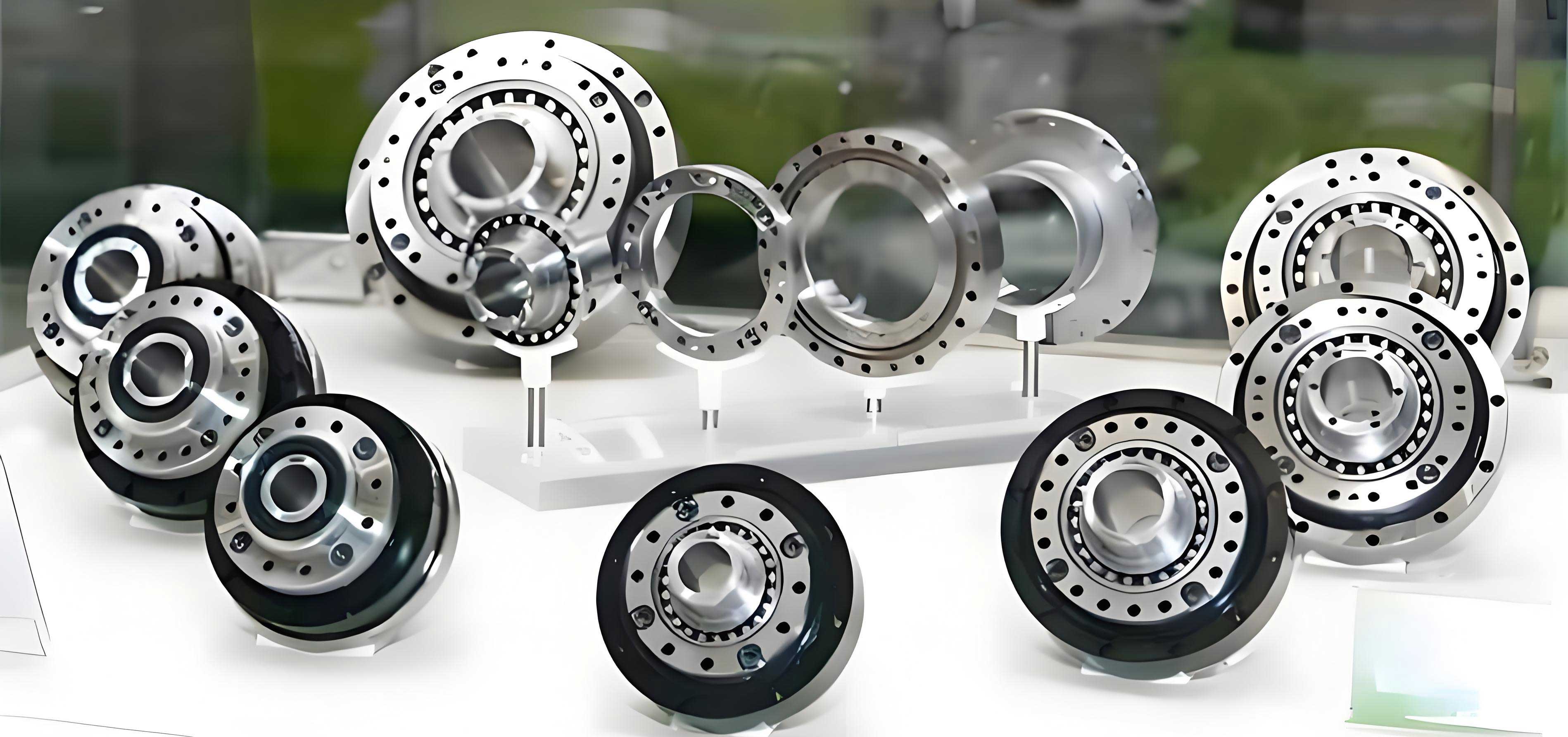
Structural Principles and Kinematics of the Rotary Vector Reducer
The operational principle of the rotary vector reducer can be understood through its two-stage power flow. The first stage is a standard involute planetary gear train. The input shaft drives the sun gear, which meshes with multiple planet gears (typically three). The second stage is the unique cycloidal drive. Each planet gear is rigidly connected to a crankshaft. This crankshaft, via a turning arm bearing, engages with a cycloidal disc, causing it to undergo an eccentric revolution. Two cycloidal discs are often mounted 180 degrees out of phase to balance forces. The cycloidal discs mesh internally with a ring of stationary pin-teeth mounted on the pin housing. The interaction between the eccentrically revolving cycloidal disc and the fixed pins forces the cycloid disc to undergo a reverse rotation relative to its revolution. This reverse rotation is transmitted through the crankshafts to the planet carrier, which serves as the output member. The overall speed reduction is the product of the ratios from both stages.
Dynamic Modeling of a Heavy-Load Rotary Vector Reducer
To accurately capture the dynamic behavior of a heavy-load rotary vector reducer, a comprehensive 16-degree-of-freedom (16-DOF) model is developed using the lumped parameter method. This model intentionally incorporates the torsional stiffness of the pin housing, a critical consideration for heavy-duty applications. The modeling is based on several key assumptions to balance complexity and accuracy: uniform mass distribution for all components, mean values for time-varying mesh stiffnesses and bearing stiffnesses represented by equivalent springs, concentrated force at the cycloid-pin mesh contact point, negligible damping and friction, omission of bending deformation in the crankshaft (as its stiffness is significantly higher than bearing stiffness), and exclusion of assembly and manufacturing errors.
The model accounts for the following degrees of freedom:
- Torsional DOFs (11 total): Sun gear, planet carrier, pin housing, two cycloidal discs, three planet gears, and three crankshafts.
- Translational DOFs (5 total): The translational motion (in the plane of rotation) of the two cycloidal discs and the three crankshafts as they revolve around the central axis.
This sums to the 16-DOF system. The linear displacements along the lines of action for the torsional vibrations are defined as:
$$ u_s = r_s \theta_s, \quad u_{pi} = r_p \theta_{pi}, \quad u_{hi} = a \theta_{hi} $$
$$ u_{cj} = r_h \theta_{cj}, \quad u_o = r_h \theta_o, \quad u_r = r_r \theta_r $$
where \( i = 1 \sim 3 \), \( j = 1 \sim 2 \), and \( \theta_s, \theta_{pi}, \theta_{hi}, \theta_{cj}, \theta_o, \theta_r \) are the angular displacements of the sun, planet gear, crankshaft, cycloid disc, carrier, and pin housing, respectively. The radii \( r_s, r_p, a, r_h, r_r \) correspond to the sun base circle, planet base circle, eccentricity, crankshaft distribution circle, and pin distribution circle.
Applying Newton’s second law, the system of differential equations governing the motion is derived. The equations for key components are summarized below:
$$ I_s \ddot{\theta}_s + k_a \theta_s + k_{spi} r_s \sum_{i=1}^{3} (u_s – u_{pi} – \eta_{hi} \cos \alpha) = T_0 $$
$$ I_{pi} \ddot{\theta}_{pi} – k_{spi} r_p (u_s – u_{pi} – \eta_{hi} \cos \alpha) + k_h (\theta_{pi} – \theta_{hi}) = 0 $$
$$ I_{hi} \ddot{\theta}_{hi} – k_h (\theta_{pi} – \theta_{hi}) + k_{hc} a \sum_{j=1}^{2} \Delta c_{ij} = 0 $$
$$ (m_{pi} + m_{hi}) \ddot{\eta}_{hi} – k_{spi} (u_s – u_{pi} – \eta_{hi} \cos \alpha) \cos \alpha – k_{hc} \sum_{j=1}^{2} \Delta c’_{ij} + k_{oh} (\eta_{hi} – u_o) = 0 $$
$$ I_{cj} \ddot{\theta}_{cj} – k_{cr} r_r \Delta cc_{jr} + k_{hc} r_h \sum_{i=1}^{3} \Delta c’_{ij} = 0 $$
$$ m_{cj} \ddot{\eta}_{cj} – k_{hc} \sum_{i=1}^{3} \Delta c_{ij} + k_{cr} \Delta cc_{jr} \cos \beta = 0 $$
$$ I_o \ddot{\theta}_o – k_{oh} r_h (\eta_{h1} + \eta_{h2} + \eta_{h3} – 3 u_o) = T_c $$
$$ I_r \ddot{\theta}_r – k_{cr} r_r \sum_{j=1}^{2} \Delta cc_{jr} \cos \beta + k_r \theta_r = 0 $$
Here, \( I, m \) denote mass moments of inertia and masses; \( k_a, k_h, k_r \) are torsional stiffnesses; \( k_{spi}, k_{cr} \) are mesh stiffnesses; \( k_{hc}, k_{oh} \) are bearing stiffnesses (crankshaft arm and carrier support); \( \alpha, \beta \) are pressure angle and equivalent mesh angle; \( \eta_{hi}, \eta_{cj} \) are translational displacements; \( T_0, T_c \) are input and output torques. The relative displacement terms \( \Delta c_{ij}, \Delta c’_{ij}, \Delta cc_{jr} \) are defined based on the system geometry and phase angles.
This system can be assembled into the canonical matrix form for a linear, undamped vibration system:
$$ \mathbf{M} \ddot{\mathbf{X}} + \mathbf{K} \mathbf{X} = \mathbf{0} $$
where \( \mathbf{M} \) is the mass matrix, \( \mathbf{K} \) is the stiffness matrix, and \( \mathbf{X} \) is the vector of generalized coordinates. The natural frequencies \( \omega_r \) and mode shapes \( \phi_r \) are found by solving the associated eigenvalue problem:
$$ ( -\omega_r^2 \mathbf{M} + \mathbf{K} ) \phi_r = \mathbf{0} $$
Inherent Characteristics of a Heavy-Duty Rotary Vector Reducer
The analysis is performed on an RV-550E type heavy-load rotary vector reducer. Its fundamental geometric and dynamic parameters, obtained from CAD modeling and standard calculations, are listed below.
| Parameter | Symbol | Value |
|---|---|---|
| Number of Sun Gear Teeth | – | 14 |
| Number of Planet Gear Teeth | – | 42 |
| Number of Cycloid Disc Teeth | – | 59 |
| Number of Pin Teeth | – | 60 |
| Module | m | 3 mm |
| Pressure Angle | α | 20° |
| Eccentricity | a | 2.2 mm |
| Sun Gear Base Circle Radius | r_s | 21 mm |
| Planet Gear Base Circle Radius | r_p | 63 mm |
| Crankshaft Distribution Circle Radius | r_h | 84 mm |
| Pin Distribution Circle Radius | r_r | 165 mm |
| Component | Mass (kg) | Moment of Inertia (kg·m²) | Relevant Stiffness (N/m or N·m/rad) |
|---|---|---|---|
| Sun Gear | 5.083 | 2.43e-3 | Torsional Stiffness \( k_a \): 3.62e6 |
| Planet Gear | 1.326 | 2.87e-3 | Mesh Stiffness \( k_{spi} \): 3.92e9 |
| Crankshaft | 1.761 | 4.73e-4 | Torsional Stiffness \( k_h \): 1.56e6 |
| Cycloid Disc | 8.562 | 0.14 | – |
| Planet Carrier | 42.96 | 0.513 | – |
| Pin Housing | 51.209 | 1.986 | Torsional Stiffness \( k_r \): 1.0e10 |
| – | – | – | Arm Bearing Stiffness \( k_{hc} \): 1.18e8 |
| – | – | – | Support Bearing Stiffness \( k_{oh} \): 3.15e8 |
| – | – | – | Cycloid-Pin Mesh Stiffness \( k_{cr} \): 3.15e10 |
Solving the eigenvalue problem yields the first six natural frequencies of this heavy-load rotary vector reducer, which are most critical for resonance avoidance.
| Mode Order | Natural Frequency (Hz) |
|---|---|
| 1 | 305 |
| 2 | 830 |
| 3 | 864 |
| 4 | 1686 |
| 5 | 1739 |
| 6 | 1750 |
The influence of pin housing torsional stiffness (\(k_r\)) on the first three natural frequencies is investigated, providing crucial insight for the design of this costly component. The results show that as \(k_r\) increases, the 1st and 2nd natural frequencies rise, but they plateau after reaching certain thresholds (approximately \(2 \times 10^7\) N·m/rad for the 1st mode and \(8 \times 10^7\) N·m/rad for the 2nd mode). This indicates a design guideline: specifying a pin housing stiffness beyond these thresholds yields diminishing returns for shifting these frequencies. Notably, the 3rd natural frequency remains completely unaffected by changes in \(k_r\), identifying it as a mode shape dominated by translational motion where the pin housing does not torsionally deform. A mode veering phenomenon is observed between the 2nd and 3rd frequencies around \(k_r = 6 \times 10^7\) N·m/rad.
Sensitivity Analysis for Design Guidance
To systematically identify which parameters most significantly influence the dynamic behavior of the rotary vector reducer, a sensitivity analysis of the natural frequencies with respect to system inertias and stiffnesses is conducted. The direct differentiation method is employed due to its clear physical interpretation and computational simplicity. For an undamped system, the sensitivity of the r-th natural frequency \( \omega_r \) to a generic parameter \( p_m \) is given by:
$$ \frac{\partial \omega_r}{\partial p_m} = – \frac{1}{2 \omega_r} \left( \omega_r^2 \phi_r^T \frac{\partial \mathbf{M}}{\partial p_m} \phi_r – \phi_r^T \frac{\partial \mathbf{K}}{\partial p_m} \phi_r \right) $$
From this, specific formulas for sensitivity to mass/inertia terms (\(m_{ij}\)) and stiffness terms (\(k_{ij}\)) are derived:
$$ \frac{\partial \omega_r}{\partial m_{ij}} = \begin{cases}
-\omega_r \phi_{ir} \phi_{jr}, & i \neq j \\
-\frac{1}{2} \omega_r \phi_{ir}^2, & i = j
\end{cases} $$
$$ \frac{\partial \omega_r}{\partial k_{ij}} = \begin{cases}
\phi_{ir} \phi_{jr} / \omega_r, & i \neq j \\
\phi_{ir}^2 / (2\omega_r), & i = j
\end{cases} $$
where \( \phi_{ir} \) is the i-th element of the r-th mass-normalized eigenvector. The sensitivity results for the first three modes are calculated and normalized for comparison. The findings are summarized in the table below and reveal clear trends for optimizing the heavy-load rotary vector reducer.
| Parameter Category | Most Sensitive Modes | Key Insight for the Rotary Vector Reducer |
|---|---|---|
| Moments of Inertia | 1st Mode: Planet Carrier 2nd & 3rd Modes: Crankshaft |
Modifying the carrier inertia most effectively tunes the fundamental frequency. Crankshaft inertia is a strong influence on higher low-frequency modes. |
| Bearing Stiffnesses (\(k_{hc}\), \(k_{oh}\)) |
All three low-order modes, especially the 1st mode to \(k_{hc}\). | Bearing stiffnesses are dominant factors. The turning arm bearing stiffness (\(k_{hc}\)) has a larger impact than the support bearing stiffness (\(k_{oh}\)), primarily due to its lower nominal value. These are practical components to modify. |
| Torsional Stiffnesses (\(k_a\), \(k_h\), \(k_r\)) |
Relatively low sensitivity for all. | Changes in shaft and housing torsional stiffness have a lesser effect on natural frequencies compared to bearing stiffnesses, within typical design ranges. |
Further analysis of the 1st natural frequency’s variation with bearing stiffness reveals a critical operational insight. If the turning arm bearing stiffness \(k_{hc}\) degrades due to wear or damage below a critical level (around \(1.2 \times 10^9\) N/m), the 1st natural frequency can drop precipitously. This increases the risk of it coinciding with the input rotation frequency or its harmonics, potentially inducing severe resonance during service. Therefore, selecting high-quality bearings, employing wear-resistant treatments, or even increasing the number of crankshafts to reduce individual bearing load are essential strategies for ensuring the long-term dynamic stability of a heavy-load rotary vector reducer.
Conclusions
This investigation into the dynamics of a heavy-load rotary vector reducer underscores the importance of comprehensive modeling and analysis for high-performance design. The established 16-DOF model, which incorporates pin housing compliance, provides a more accurate tool for predicting the natural frequencies of heavy-duty variants. The analysis confirms that for such a rotary vector reducer, the low-order natural frequencies are most sensitive to the stiffness of the turning arm bearings and the support bearings, as well as the inertia of the planet carrier and crankshafts. The pin housing stiffness, while important, exhibits a saturating effect on frequency shift, offering a cost-effective design limit. Crucially, the sensitivity and parametric studies highlight that maintaining bearing integrity is vital for preventing operational resonance due to frequency drift caused by wear. These results form a solid theoretical foundation for the targeted structural optimization of heavy-load rotary vector reducers, guiding designers to prioritize bearing selection and critical inertia components to enhance dynamic performance and operational reliability.