
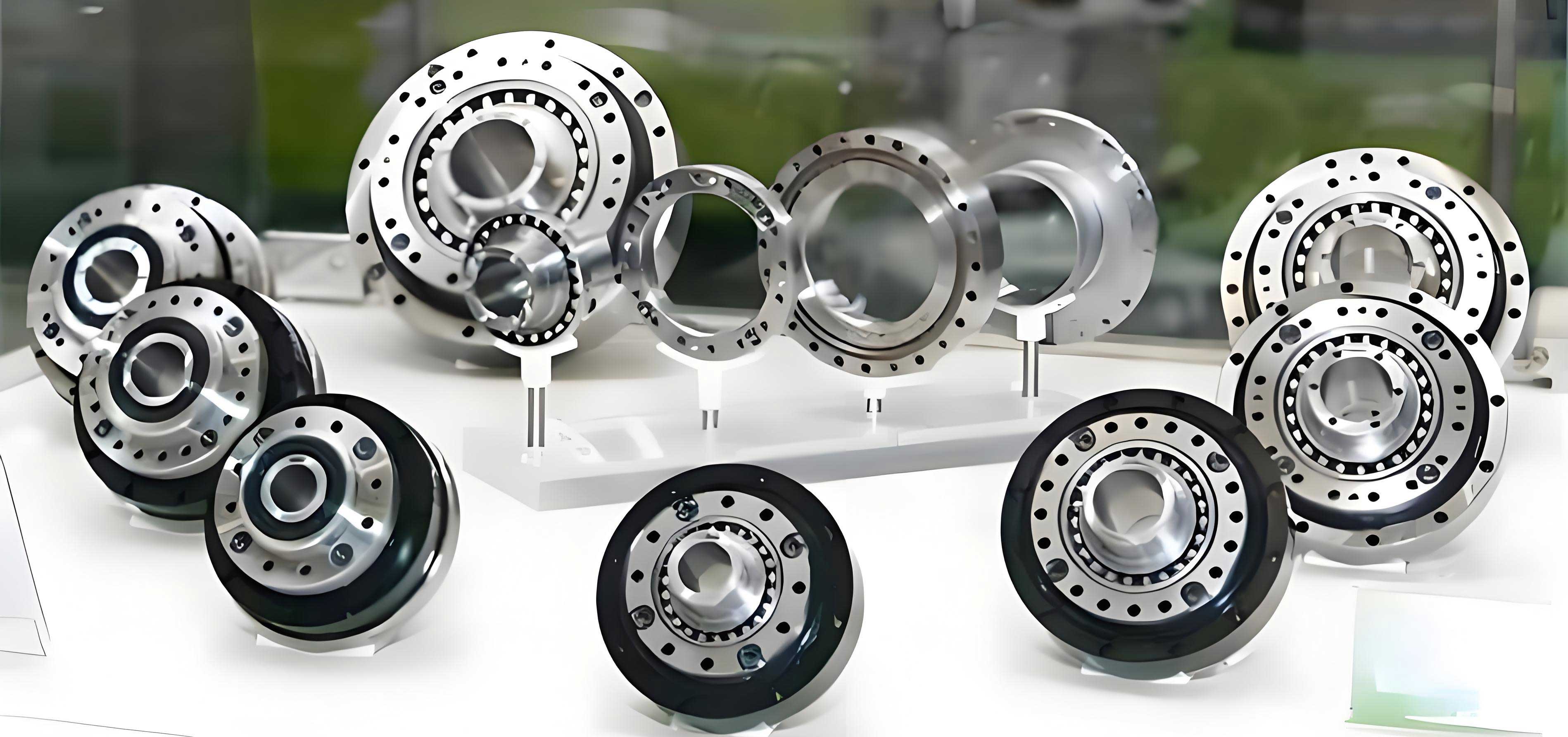
The pursuit of precision, compactness, and high torque density in modern robotic drivetrains has established the rotary vector reducer as a paramount component. As the core transmission element within an industrial robot’s joints, its performance directly dictates the system’s accuracy, stiffness, and long-term reliability. The unique two-stage reduction mechanism of the rotary vector reducer offers exceptional advantages, including high reduction ratios, minimal backlash, excellent torsional rigidity, and a compact form factor. This article delves into the advanced design and rapid prototyping of its most critical component—the cycloidal disk—through parametric modeling and Fused Deposition Modeling (FDM), presenting a modern, iterative workflow for development and validation.
The operational principle of a standard rotary vector reducer hinges on a compound planetary-cycloidal system. The first stage is a conventional planetary gear train. An input shaft, often connected directly to a servo motor, drives a central sun gear. This sun gear meshes with multiple planet gears (typically three), which are housed within a planet carrier, achieving the initial speed reduction. The second, and most distinctive, stage involves a cycloidal drive. The planet gears are mounted on eccentric crankshafts (or simply “eccentrics”). These crankshafts, rotating with the planet carrier, act as the input to the cycloidal stage. A pair of cycloidal disks, offset by 180 degrees, are mounted on these eccentrics. The disks engage with a stationary ring of cylindrical pins (the pin wheel) housed in the reducer’s casing. As the eccentrics rotate (carrying the cycloidal disks in a orbital motion), the meshing between the cycloid teeth and the stationary pins forces the cycloidal disks to rotate on their own axis, but in the opposite direction to the orbital motion. This “counter-rotation” is the second reduction stage. The slow rotation of the cycloidal disks is then transferred to the output flange through a series of pins or a parallel crank mechanism, resulting in a very high overall reduction ratio in a remarkably stiff and compact assembly. The design of the rotary vector reducer is thus a sophisticated balance between these kinematic stages.
At the heart of this mechanism lies the cycloidal disk. Its performance is more sensitive to geometric precision than perhaps any other part in the rotary vector reducer. Unlike involute gears, the cycloidal tooth profile provides multi-tooth simultaneous contact, distributing the load across several teeth and leading to high shock load capacity, smooth motion, and theoretically zero backlash. The accurate generation of this profile is therefore the cornerstone of designing an effective rotary vector reducer.
Mathematical Foundation: Deriving the Cycloidal Tooth Profile
The ideal tooth profile of a cycloidal disk is a curtate epicycloid. It can be visualized as the path traced by a point on the circumference of a rolling circle (the generating circle) as it rolls without slipping on the outside of a fixed base circle (the pin circle). For a functional rotary vector reducer, this generated curve must then be offset by the radius of the pin rollers to create the actual working tooth flank.
The fundamental parametric equations begin with the pure epicycloid. Let \( R_p \) be the radius of the pin center circle (the fixed base circle), \( r_g \) be the radius of the rolling generating circle, and \( \theta \) be the rotation angle of the generating circle. The coordinates of a point on the rim of the generating circle are:
$$ x = (R_p + r_g) \cos \theta – r_g \cos\left(\frac{R_p + r_g}{r_g} \theta\right) $$
$$ y = (R_p + r_g) \sin \theta – r_g \sin\left(\frac{R_p + r_g}{r_g} \theta\right) $$
In a standard epicycloid, the generating circle rolls externally. For the curtate epicycloid used in a rotary vector reducer, the tracing point is *inside* the generating circle’s circumference. This is introduced by modifying the terms involving the generating circle radius \( r_g \) with a tracing point distance \( r_t \), where \( r_t < r_g \). Furthermore, the relationship between the circles is defined by the number of pins \( Z_p \) on the fixed ring and the number of lobes (teeth) \( Z_c \) on the cycloidal disk. The fundamental design rule is \( Z_p = Z_c + 1 \). The ratio \( R_p / r_g = Z_p \).
Introducing the eccentricity \( a \), which is the distance between the center of the generating circle and the center of the cycloidal disk (and also the crank throw), we have \( a = R_p – r_g \). A more practical form uses the shortening coefficient \( K \), defined as:
$$ K = \frac{a Z_p}{R_p} = 1 – \frac{r_g Z_p}{R_p} $$
The value of \( K \) is critical; it determines the “fullness” or “curtateness” of the tooth. A value between 0.65 and 0.90 is typical for high-performance rotary vector reducers to ensure proper tooth strength and contact conditions.
The final parametric equations for the theoretical tooth profile of a cycloidal disk, before offset for pin radius, are thus expressed as:
$$ x = R_p \left[ \cos(\theta) – \frac{K}{Z_p} \cos(Z_p \theta) \right] $$
$$ y = R_p \left[ \sin(\theta) – \frac{K}{Z_p} \sin(Z_p \theta) \right] $$
Here, \( \theta \) is the parameter, typically varied from \( 0 \) to \( 2\pi \) to generate one full tooth profile. Since the profile has \( Z_c \) lobes, it will repeat every \( 2\pi / Z_c \) radians of the parameter \( \theta \). To generate the actual machinable profile, these coordinates must be offset outwardly by the pin roller radius \( r_{rp} \) along the normal to the curve. This offset operation is computationally intensive and is a key step in parametric CAD.
For design purposes, key parameters must be selected from established standards and validated through stress and contact analysis. The following table summarizes critical initial design parameters for a sample rotary vector reducer cycloidal stage.
| Parameter | Symbol | Sample Value | Design Notes |
|---|---|---|---|
| Number of Pin Teeth | \( Z_p \) | 36 | Fixed ring. |
| Number of Cycloid Lobes | \( Z_c \) | 35 | \( Z_p = Z_c + 1 \). |
| Pin Center Circle Radius | \( R_p \) | 85.0 mm | Determines overall size. |
| Pin Roller Radius | \( r_{rp} \) | 3.0 mm | Subject to Hertzian contact stress. |
| Eccentricity (Crank Throw) | \( a \) | 1.75 mm | Key for reduction ratio & size. |
| Shortening Coefficient | \( K \) | 0.7206 | Calculated as \( aZ_p / R_p \). |
| Tooth Width | \( W \) | 14.0 mm | Affects bending strength. |
With \( R_p = 85 \) mm and \( a = 1.75 \) mm, the shortening coefficient calculates to \( K = (1.75 \times 36) / 85 \approx 0.7206 \), which falls within the recommended range for robust design. Substituting these values into the parametric equations yields the specific curve for modeling:
$$ x(\theta) = 85.0 \left[ \cos(\theta) – \frac{0.7206}{36} \cos(36\theta) \right] $$
$$ y(\theta) = 85.0 \left[ \sin(\theta) – \frac{0.7206}{36} \sin(36\theta) \right] $$
This curve, when offset by \( r_{rp} = 3.0 \) mm, defines the precise tooth flank geometry for this instance of a rotary vector reducer.
Parametric Modeling Workflow for the Cycloidal Disk
The transition from mathematical equations to a manufacturable 3D model is efficiently achieved through parametric modeling. Software like SolidWorks, Creo Parametric, or Siemens NX allows the designer to embed the governing equations directly into the sketch geometry, creating an “intelligent” model that updates dynamically when key parameters (e.g., \( R_p \), \( Z_p \), \( a \)) are changed. This is indispensable for the iterative design process of a rotary vector reducer.
The workflow proceeds as follows:
1. Equation-Driven Curve: Within the CAD software’s sketching environment, the tool for creating an equation-driven curve (or “parametric spline”) is activated. The modified equations, accounting for the pin radius offset, are entered. The parameter \( \theta \) (often renamed as a variable like ‘t’) is defined to sweep from 0 to a value sufficient to create one complete lobe, typically \( 2\pi / Z_c \) (approximately 0.1795 rad for \( Z_c=35 \)).
2. Pattern Generation: The single lobe curve is then patterned circularly around the disk’s center point. The number of instances in the pattern is set to \( Z_c \) (35). This creates the complete, closed tooth profile sketch.
3. Disk Body Creation: The central hub and crank bearing bores are added to the sketch. The entire profile is then extruded to the designed tooth width \( W \).
4. Parameter Linking: Key dimensions—such as the pin circle diameter (\( 2R_p \)), the offset distance for the curve (linked to \( r_{rp} \)), and the pattern count—are defined as named parameters in a global table or via equations. Changing the master parameter values automatically regenerates the entire cycloidal disk model. This parametric model becomes a powerful template for generating different sizes and ratios of rotary vector reducer disks rapidly.
Rapid Prototyping via Fused Deposition Modeling (FDM)
Traditional manufacturing of cycloidal disks for a rotary vector reducer, such as precision hobbing or grinding, requires expensive, dedicated tooling and is time-consuming for prototypes. Additive Manufacturing (AM), specifically Fused Deposition Modeling (FDM), offers a compelling alternative for functional prototyping, design validation, and even low-volume production of specialized reducers. FDM builds parts layer-by-layer by extruding a thermoplastic filament through a heated nozzle.
The process for creating a functional cycloidal disk prototype via FDM involves several critical steps:
1. Data Preparation and Slicing: The parametric 3D CAD model is exported in a tessellated format, typically STL (Standard Tessellation Language). This file is imported into slicing software (e.g., Ultimaker Cura, PrusaSlicer). The slicer’s role is to convert the 3D shape into a series of 2D layers (slices) and generate the toolpath (G-code) for the printer.
2. Key Process Parameter Selection: The choice of parameters profoundly affects the prototype’s dimensional accuracy, mechanical strength, and surface finish—all critical for a component like a rotary vector reducer disk. A sample parameter set is outlined below:
| Parameter | Setting | Rationale for Cycloidal Disk |
|---|---|---|
| Layer Height | 0.1 – 0.15 mm | Fine layers improve Z-axis resolution and tooth profile accuracy, reducing “stair-stepping”. |
| Infill Density & Pattern | 60-80%, Gyroid/Grid | High density is needed for structural rigidity under load. Gyroid offers good isotropic strength. |
| Wall/Perimeter Count | 4-6 | Multiple perimeters ensure strong, continuous tooth flanks and improve dimensional stability. |
| Printing Temperature | Material-specific (e.g., 215°C for PLA) | Optimal for layer adhesion and flow. |
| Build Plate Temperature | 60°C (for PLA) | Prevents warping and ensures strong first-layer adhesion. |
| Print Speed | 40-60 mm/s (outer walls slower) | Slower speeds on perimeters improve surface finish on critical tooth profiles. |
| Support Structure | Typically “None” | Cycloidal disks are generally prismatic in the Z-direction; no overhangs require support. |
3. Material Selection: While PLA is common for visual prototypes, engineering thermoplastics are preferred for functional testing of a rotary vector reducer component.
– PETG: Offers a good balance of strength, toughness, and thermal resistance, with low warping.
– ABS: Provides higher temperature resistance and toughness but requires a heated chamber to prevent cracking.
– Nylon (PA6/PA66): Excellent wear resistance and toughness, ideal for simulating the sliding/rolling contact in a reducer, though hygroscopic and challenging to print.
– Composite Filaments (e.g., Carbon Fiber reinforced): Significantly increase stiffness and strength, allowing prototypes to withstand higher loads during kinematic testing.
4. Printing and Post-Processing: The G-code is transferred to the FDM printer. After a leveling and heating sequence, the build begins. Post-processing involves removal from the build plate, and potentially light sanding of the tooth flanks or vapor smoothing (for materials like ABS) to reduce surface roughness and improve meshing smoothness. For a rotary vector reducer prototype, the bearing bores may require reaming to achieve precise tolerances for the eccentric bearings.
Precision Analysis and Compensatory Design Strategies
While FDM is highly capable, achieving the micron-level tolerances of a production-grade rotary vector reducer is challenging. A systematic analysis of error sources is essential for creating functional, test-worthy prototypes.
| Error Source | Effect on Cycloidal Disk | Typical Magnitude | Compensation Strategy |
|---|---|---|---|
| FDM Shrinkage/Warping | Overall part contraction, bore diameter reduction, tooth profile scaling. | 0.2% – 0.8% linear shrinkage. | Scale up the CAD model in the slicer (e.g., 100.4% on X/Y). Perform test prints and measure to determine exact scaling factor for the material/printer. |
| Layer Adhesion & Anisotropy | Reduced strength in the Z-direction. “Stair-step” effect on inclined tooth flanks. | Z-strength can be 30-80% of XY strength. | Orient the disk flat on the build plate (XY-plane). Use high perimeter count and optimal temperature for layer bonding. |
| Nozzle Diameter & Path Width | “Over-extrusion” can cause features like tooth tips to be thicker than designed. “Under-extrusion” can make them thinner. | Feature size deviation on the order of the nozzle diameter (0.4mm). | Calibrate extrusion multiplier (flow rate). Design parametric tolerances: slightly widen tooth root clearance in the CAD model to account for potential flank material accumulation. |
| Belt Backlash & Stepper Resolution | Minor inaccuracies in curve reproduction, especially at high curvatures. | Typically < 0.1mm positional error. | Use printers with direct-drive extruders and high-quality motion components. Minor errors are often within acceptable limits for prototype kinematic validation. |
| Thermal Expansion During Print | Localized distortion as newly deposited hot material cools. | Difficult to quantify; contributes to general shape inaccuracy. | Ensure stable, draft-free printing environment. Use an enclosed printer for materials like ABS. |
The most effective proactive strategy is compensatory parametric design. Instead of modeling the nominal theoretical profile, the designer modifies the governing equations in the CAD model to anticipate the dominant systematic error—typically uniform shrinkage. For example, if measurement of a test print indicates a consistent 0.4% undersize on critical diameters, the master parameter \( R_p \) in the equation can be increased by 0.4% in the parametric model itself:
$$ R_{p,\text{compensated}} = R_{p,\text{nominal}} \times (1 + 0.004) = 85.0 \times 1.004 = 85.34 \text{ mm} $$
This adjusted value is then used in the parametric equations. When this “pre-scaled” model is printed and naturally shrinks, it arrives much closer to the intended nominal dimensions. This closed-loop process of design-print-measure-compensate is key to producing highly accurate functional prototypes for a rotary vector reducer.
In conclusion, the integration of rigorous parametric modeling based on precise cycloidal equations with the agile capabilities of FDM additive manufacturing creates a powerful development ecosystem for the rotary vector reducer. This approach demystifies the design of the complex cycloidal disk, enabling rapid iteration, functional testing of novel tooth profiles or bearing arrangements, and significant acceleration of the development cycle. While the absolute precision of mass-production methods is not yet fully replicated, the ability to hold controlled tolerances through compensatory design allows engineers to validate kinematics, assembly fits, and basic load performance long before committing to expensive tooling. As materials and AM technologies continue to advance, this synergy between digital design and additive fabrication will undoubtedly play an increasingly central role in innovating the next generation of high-performance rotary vector reducers.