
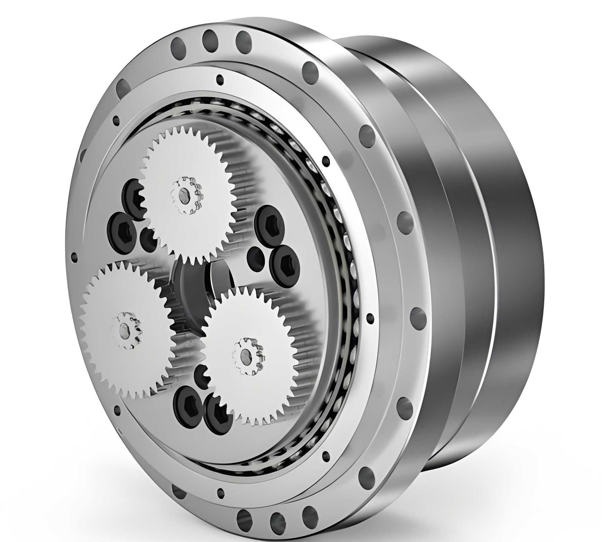
The pursuit of higher performance, compactness, and reliability in precision transmission systems, particularly for applications like industrial robots, is a continuous engineering challenge. The rotary vector reducer stands as a cornerstone in this field, renowned for its high torque density, compact size, and excellent positional accuracy. Traditionally, this reducer combines a first-stage involute planetary gear train with a second-stage cycloidal-pin wheel planetary mechanism utilizing an external cycloidal disc. This paper introduces a significant structural innovation: a novel rotary vector reducer where the second-stage transmission is replaced by an internal-cycloid planetary mechanism. This reconfiguration offers distinct advantages, including an inherently compact axial profile, an enlarged central hollow space, and the potential for improved dynamic performance. The following analysis details the design principles, virtual prototype simulation, and dynamic characteristic evaluation of this novel internal-cycloid based rotary vector reducer.
The operational principle of the proposed reducer retains the two-stage speed reduction characteristic of a standard rotary vector reducer but modifies its kinematic core. The first stage remains an involute planetary gear set, providing an initial speed reduction and power branching. The revolutionary change lies in the second stage. Instead of an external cycloid disc meshing with stationary pin gears housed in a casing, this design employs an internal cycloid gear. This internal gear rotates and meshes with pin gears that are mounted on the output flange. The motion is transferred from the first-stage planetary carrier to the internal cycloid gear via eccentric crank shafts, creating a controlled planetary motion of the internal gear relative to the pins. The anti-rotation of the internal cycloid gear is constrained, forcing its planetary motion to drive the pin-equipped output flange, thereby achieving the final, high-ratio speed reduction. This inversion of the traditional meshing arrangement is the key to its structural benefits.
The design process begins with the mathematical generation of the internal cycloid tooth profile. The theoretical tooth flank of the internal gear is derived from a shortened hypocycloid. As a generating circle of radius $r$ rolls without slipping inside a fixed base circle of radius $R_z$, a point $M$ attached to the generating circle traces the shortened hypocycloid. The center positions of the pin gears are located on the equidistant curve of this hypocycloid. The fundamental parametric equations governing this profile are critical for precise manufacturing and analysis of the rotary vector reducer.
The coordinates $(x_0, y_0)$ of the theoretical internal cycloid profile are given by:
$$
\begin{align*}
x_0 &= \frac{z_b}{K_1}A\cos\psi + A\cos(z_b\psi) \\
y_0 &= \frac{z_b}{K_1}A\sin\psi + A\sin(z_b\psi)
\end{align*}
$$
where $z_b$ is the number of pin gears, $K_1$ is the shortening coefficient of the theoretical profile ($K_1 = OM / r$), $A$ is the eccentricity (the distance between the base circle center and the crank axis), and $\psi$ is the rotation angle of the generating circle’s center around the base circle center.
Accounting for the pin radius $r_z$, the equation for the actual working tooth profile of the internal cycloid gear in the rotary vector reducer becomes:
$$
\begin{align*}
x &= \cos\psi\left( \frac{A z_b}{K_1} + \frac{r_z}{W_1′} \right) + \cos(z_b\psi)\left( A – \frac{K_1 r_z}{W_1′} \right) \\
y &= \sin\psi\left( \frac{A z_b}{K_1} + \frac{r_z}{W_1′} \right) – \sin(z_b\psi)\left( A – \frac{K_1 r_z}{W_1′} \right)
\end{align*}
$$
Here, $W_1′ = \sqrt{1 + K_1^2 – 2K_1\cos\left[(z_b+1)\psi\right]}$.
Based on these principles, a specific design of the novel rotary vector reducer was developed. The primary design goals were to achieve a high reduction ratio, structural compactness, and high load capacity. A comparative overview of the key structural differences between the traditional and the novel rotary vector reducer is summarized in Table 1.
| Feature | Traditional RV Reducer | Novel Internal-Cycloid RV Reducer |
|---|---|---|
| Second-Stage Type | External Cycloid-Pin Drive | Internal Cycloid-Pin Drive |
| Cycloid Component | External Cycloid Disc(s) | Internal Cycloid Gear |
| Pin Location | Fixed in Housing | Mounted on Output Flange |
| Output Member | Flange connected to Cycloid Disc carrier | Flange integrated with Pin carrier |
| Inherent Hollow Space | Moderate | Large |
| Axial Stack Length | Standard | Potentially Shorter |
The main technical parameters selected for the virtual prototype of this novel rotary vector reducer are listed in Table 2. These parameters ensure a significant reduction ratio and define the geometric constraints for modeling.
| Parameter | Value | Unit |
|---|---|---|
| Pin Distribution Circle Diameter | 50 | mm |
| Pin Diameter | 4 | mm |
| Crank Eccentricity, $A$ | 1 | mm |
| Number of Internal Cycloid Gear Teeth, $z_a$ | 41 | – |
| Number of Pin Gears, $z_b$ | 40 | – |
| Sun Gear (Input) Teeth | 102 | – |
| Planet Gear Teeth | 17 | – |
| Ring Gear (Fixed) Teeth | 63 | – |
| Gear Module (First Stage) | 2 | mm |
| Motor Input Speed | 1500 | rpm |
| Motor Output Pinion Teeth | 34 | – |
The total reduction ratio $i_{total}$ of this rotary vector reducer can be calculated using the formula for compound planetary systems:
$$
i_{total} = \left(1 + \frac{z_{ring}}{z_{sun}}\right) \times \frac{z_a}{z_a – z_b}
$$
Where $z_{ring}$ is the fixed ring gear tooth count, $z_{sun}$ is the input sun gear tooth count, $z_a$ is the number of internal cycloid gear teeth, and $z_b$ is the number of pin gears. For the chosen parameters, this yields a high theoretical reduction ratio. A 3D model was meticulously built using CAD software, incorporating all major components like the internal cycloid gear, crank shafts, planetary gears, sun gear, and the output flange with pins. This model served as the basis for subsequent dynamic analysis.
To validate the kinematic and dynamic performance of the novel rotary vector reducer design, a multi-body dynamics simulation was performed using ADAMS software. The imported CAD assembly was assigned realistic material properties, joints, and constraints to create a virtual prototype. The first-stage gear meshes were modeled as geared constraints, while the critical second-stage contacts between the internal cycloid gear teeth and the pin gears were modeled using a robust impact-based contact force algorithm (IMPACT function). This accurately captures the fluctuating contact forces during operation. The simulation conditions were set to reflect a typical robotic servo application: a motor input speed of 1500 rpm was applied to the motor pinion, which meshes with the 102-tooth sun gear, resulting in an effective sun gear input speed of approximately 500 rpm (3000 °/s). A constant load torque of 681 N·m was applied to the output flange to simulate a working load.
The simulation results confirmed the fundamental kinematic correctness of the novel rotary vector reducer design. The angular velocity of the output flange stabilized at the expected reduced speed, accurately reflecting the designed high reduction ratio. The motion of the internal cycloid gear itself is complex, involving both rotation and orbital translation. The simulation traced the centroidal velocity of the internal cycloid gear. The X and Y components of this velocity were plotted over one full revolution of the output, revealing perfect sinusoidal and cosinusoidal waveforms, respectively. This pattern conclusively demonstrates that the internal cycloid gear undergoes a smooth, circular planetary motion around the central axis of the rotary vector reducer, precisely as the theoretical design intended.
A paramount aspect of evaluating any rotary vector reducer is understanding its load distribution and internal force dynamics. The contact forces between the internal cycloid gear and the pin gears are of particular interest. The simulation extracted the contact force history for a representative pin gear during engagement. Figure 9 (referencing the force component plots from the source, but not by number in this text) shows that the contact force components in the X and Y directions also follow periodic, wave-like patterns—closely resembling sinusoidal and cosinusoidal functions, respectively. This periodic fluctuation is inherent to cycloidal meshing and is influenced by factors such as the changing contact angle, elastic deformations, and minor vibrations within the multi-body system. The magnitude and pattern of these forces are crucial for stress analysis and fatigue life prediction of the rotary vector reducer components. Key results from the dynamics simulation are consolidated in Table 3.
| Simulated Parameter | Result | Observation | |
|---|---|---|---|
| Output Angular Velocity | Stable at ~278 °/s | Matches theoretical reduction ratio from 3000 °/s input. | |
| Internal Cycloid Gear Motion | Sinusoidal centroid velocity | Confirms pure rotational + orbital planetary motion. | |
| Pin-Cycloid Contact Force Pattern | Periodic, wave-like fluctuation | Characteristic of cycloidal meshing; vital for stress analysis. | |
| System Stability | Steady-state achieved | No kinematic lock or instability observed under load. |
Beyond kinematics and static loading, the dynamic vibrational characteristics of the rotary vector reducer are critical for ensuring smooth operation and avoiding resonant failures. A modal analysis was conducted using the Finite Element Method (FEM) on both the key components and the fully constrained reducer assembly. This analysis determines the natural frequencies and corresponding mode shapes of the structure. The results for the first 12 natural frequencies of the assembled reducer are presented in Table 4, alongside the constrained modal frequencies of two critical components: the crank shaft and the internal cycloid gear.
| Mode Order | Full Assembly Frequency (Hz) | Crank Shaft (Constrained) Frequency (Hz) | Internal Cycloid Gear (Constrained) Frequency (Hz) |
|---|---|---|---|
| 1 | 2455.0 | 16648.0 | 649.7 |
| 2 | 2542.9 | 16730.0 | 1126.1 |
| 3 | 2624.8 | 33355.0 | 1924.6 |
| 4 | 2718.3 | 33947.0 | 3116.9 |
| 5 | 2876.6 | 37955.0 | 3178.3 |
| 6 | 2965.6 | 46421.0 | 4107.9 |
| 7 | 2986.7 | 58858.0 | 4634.8 |
| 8 | 3059.5 | 64640.0 | 5273.6 |
| 9 | 3110.3 | 64840.0 | 5608.9 |
| 10 | 3435.5 | 71486.0 | 5965.0 |
| 11 | 3559.2 | 73294.0 | 6577.7 |
| 12 | 3587.2 | 73502.0 | 7284.4 |
The analysis reveals that the first natural frequency of the fully assembled novel rotary vector reducer is above 2455 Hz. The primary excitation frequencies during operation are significantly lower. For instance, the rotational frequency of the input sun gear is approximately 8.3 Hz (500 rpm/60), and the output flange rotates at about 0.77 Hz. Therefore, the operational frequencies are orders of magnitude below the system’s lowest natural frequency, effectively eliminating the risk of resonance during normal service—a crucial requirement for a precision rotary vector reducer used in robotics. The table also allows for component-specific analysis. For example, the fourth natural frequency of the isolated internal cycloid gear (3116.9 Hz) is close to the ninth assembly frequency (3110.3 Hz). This insight is valuable for targeted design optimization, such as adding strategic stiffening ribs to the internal cycloid gear to shift its local frequency if necessary, thereby avoiding potential component-level resonant coupling within the rotary vector reducer assembly.
In conclusion, this study has successfully presented and analyzed a novel internal-cycloid based rotary vector reducer. The design principles, rooted in hypocycloid geometry, were detailed, leading to the development of a functional 3D model. Comprehensive multi-body dynamics simulations proved the design’s kinematic validity, demonstrating correct motion transfer, stable reduction ratio, and characteristic cycloidal contact force patterns. Furthermore, a modal analysis confirmed the structural integrity of the design, showing that its natural frequencies are well separated from operational excitation frequencies. The proposed rotary vector reducer architecture offers tangible benefits over the traditional design, including a more compact axial form factor, a larger central passage for cables or shafts, and a potentially more rigid output structure. The methodologies and findings presented here provide a robust reference framework for the design, simulation, and dynamic analysis of similar high-precision cycloidal and rotary vector reducer transmissions, contributing to the advancement of compact, high-performance drive technology.