
In the field of precision machinery, the rotary vector reducer plays a critical role due to its compact design, high torque capacity, and exceptional positioning accuracy. As a key component in industrial robots, machine tools, and medical devices, the performance of the rotary vector reducer directly impacts system efficiency and longevity. This study focuses on the contact behavior of the cycloidal pin wheel pair within the rotary vector reducer, employing finite element analysis to explore the transient meshing state under load conditions. By developing a detailed three-dimensional model and simulating realistic operational scenarios, we aim to provide insights into stress distribution and deformation patterns that influence the durability and reliability of the rotary vector reducer.
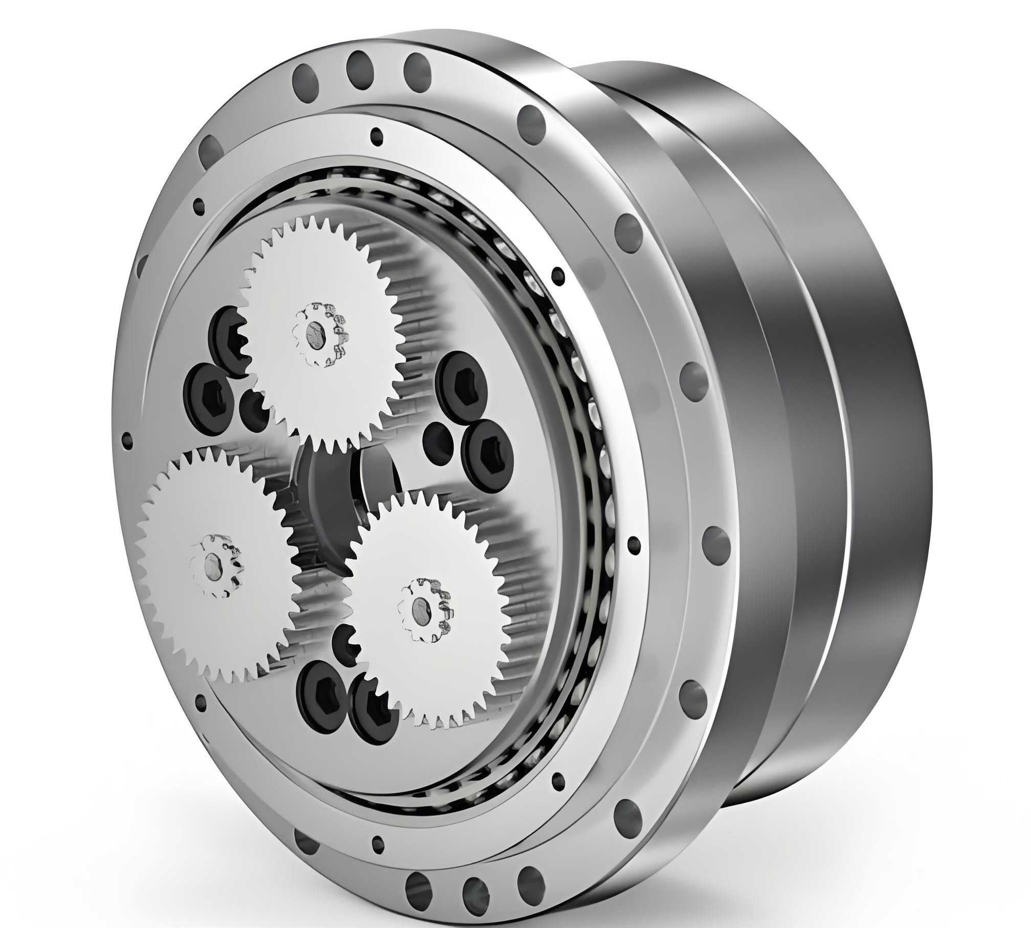
The rotary vector reducer operates through a two-stage reduction mechanism. The first stage involves an involute planetary gear system, while the second stage comprises a cycloidal pin wheel planetary mechanism. This dual-stage design enables the rotary vector reducer to achieve high reduction ratios within a confined space. The core of the second stage is the interaction between the cycloidal gear and the pin wheel, where accurate meshing dictates the overall performance. Understanding the contact dynamics during initial engagement is essential for optimizing the design of the rotary vector reducer, particularly in terms of load distribution and wear resistance.
To model the cycloidal pin wheel pair, we first define the geometric parameters based on standard design principles for the rotary vector reducer. The cycloidal gear profile is derived from a mathematical equation that accounts for the rolling motion of a circle around another circle. The parametric equations for the cycloidal tooth profile are given by:
$$ x = (R_p – r_p) \cos(\theta) + e \cos(Z_p \theta) – r_c \cos(\phi) $$
$$ y = (R_p – r_p) \sin(\theta) + e \sin(Z_p \theta) – r_c \sin(\phi) $$
where $R_p$ is the pitch radius of the pin wheel, $r_p$ is the radius of the pin, $e$ is the eccentricity, $Z_p$ is the number of pins, $\theta$ is the rotation angle, $r_c$ is the radius of the cycloidal gear, and $\phi$ is related to $\theta$ through the gear ratio. For the rotary vector reducer analyzed here, specific values are summarized in the table below.
| Parameter | Symbol | Value | Unit |
|---|---|---|---|
| Number of Cycloidal Teeth | $Z_c$ | 39 | – |
| Number of Pins | $Z_p$ | 40 | – |
| Pin Wheel Radius | $R_p$ | 52.5 | mm |
| Pin Radius | $r_p$ | 2.35 | mm |
| Eccentricity | $e$ | 0.9 | mm |
| Cycloidal Gear Pitch Radius | $r_c$ | 35.1 | mm |
| Pin Wheel Pitch Radius | $r_{pw}$ | 36 | mm |
| Bearing Hole Radius | $l$ | 24 | mm |
| Cycloidal Gear Width | $b$ | 8.9 | mm |
| Output Speed | $n$ | 15 | rpm |
Profile modification is often applied to the cycloidal gear to enhance meshing performance and reduce stress concentrations in the rotary vector reducer. The modification amounts include a radial shift $\Delta r$ and a pin wheel radius adjustment $\Delta R_p$. These values are determined based on lubrication and load requirements, as shown in the following table.
| Profile Type | Radial Modification $\Delta r$ (μm) | Pin Wheel Modification $\Delta R_p$ (μm) |
|---|---|---|
| Standard Cycloidal Gear | 0 | 0 |
| Modified Cycloidal Gear | 5.69 | -3.68 |
The material properties for both the cycloidal gear and pins are consistent, typical of high-strength alloy steels used in rotary vector reducer applications. The elastic modulus $E$ and Poisson’s ratio $\nu$ are:
$$ E = 2.06 \times 10^{11} \, \text{Pa}, \quad \nu = 0.3 $$
These properties ensure accurate simulation of elastic deformations under operational loads.
Building the finite element model requires careful consideration of mesh quality and computational efficiency. We use ANSYS Parametric Design Language (APDL) to create a parameterized three-dimensional model of the cycloidal pin wheel pair. This approach avoids geometric inaccuracies that may arise from importing CAD files. The cycloidal tooth profile is discretized into a series of points using the profile equations, and a B-spline curve is fitted through these points to form a single tooth. The complete gear profile is generated by replicating this tooth around the gear axis. Boolean operations are then applied to create holes for the crankshaft and output pins, essential components in the rotary vector reducer assembly.
For meshing, we select SOLID185 hexahedral elements due to their high accuracy and robustness in contact analysis. Each element has eight nodes with three degrees of freedom per node, suitable for simulating complex stress states in the rotary vector reducer. To balance detail and computation time, we refine the mesh near the contact surfaces where stress gradients are high. The global element size is set to 1 mm, while the tooth profile edges are meshed with a size of 0.25 mm. The VSWEEP command is employed to generate a structured hexahedral mesh, ensuring element quality and reducing skewness. The resulting finite element model comprises approximately 500,000 elements, capturing the intricate geometry of the cycloidal pin wheel pair in the rotary vector reducer.
Contact pairs are defined to simulate the interaction between the cycloidal gear teeth and the pins. Since both components are deformable, we use surface-to-surface contact with the cycloidal gear as the target surface and the pins as the contact surface. The contact elements are TARGE170 and CONTA174, respectively. Key contact properties include a friction coefficient of 0.3 to account for sliding friction, which is common in rotary vector reducer operation. The augmented Lagrangian method is chosen for contact resolution due to its stability in handling large deformations. Initial gaps are preserved without automatic adjustment to reflect the modified profile, and penetration is eliminated through iterative solutions. We establish 13 potential contact pairs around the gear to model the initial meshing phase, as the rotary vector reducer transitions from single-tooth to multi-tooth contact under load.
Boundary conditions and loads are applied to mimic the actual working environment of the rotary vector reducer. The pin wheel is fixed in space, while the cycloidal gear undergoes both rotation and orbital motion. Constraints are applied to the pins to restrict translational and rotational degrees of freedom except for rotation about their axes. For the cycloidal gear, we create multipoint constraints (MPC184) at the crankshaft hole centers and the gear center to simulate the connection to the crankshaft and output mechanism. A mass element (MASS21) is added at the gear center to represent eccentric motion. The output torque $T$ of 167 N·m is applied as a rotational load, corresponding to the rated capacity of the rotary vector reducer. The equation for torque transmission in the cycloidal stage can be expressed as:
$$ T = F_t \cdot r_c \cdot Z_c $$
where $F_t$ is the tangential force per tooth. However, due to multi-tooth contact, the load distribution is non-uniform, which our finite element analysis aims to capture.
Under the applied load, the initial meshing state of the cycloidal pin wheel pair reveals significant insights. The von Mises stress distribution shows that six teeth simultaneously participate in load transmission at the moment of engagement, contrary to the single-tooth contact in unloaded conditions. This multi-tooth contact is attributed to elastic deformation of the cycloidal gear, which compensates for profile modifications and clearances in the rotary vector reducer. The maximum contact stress occurs at the sixth tooth, indicating it is the first to engage. The contact stress $\sigma_c$ between the cycloidal tooth and pin can be approximated by the Hertzian contact theory for cylindrical surfaces:
$$ \sigma_c = \sqrt{\frac{F}{\pi b} \cdot \frac{1/R_1 + 1/R_2}{1/E_1 + 1/E_2}} $$
where $F$ is the contact force, $b$ is the gear width, $R_1$ and $R_2$ are the radii of curvature, and $E_1$ and $E_2$ are the elastic moduli. However, the finite element results provide a more detailed distribution due to complex geometry and multi-tooth interaction in the rotary vector reducer.
The deformation analysis further elucidates the behavior of the cycloidal gear. The nodal displacement vector plot indicates that displacements increase radially outward from the gear center, aligning with the eccentric motion in the rotary vector reducer. Near the contact zones, the tooth profiles exhibit inward deformation due to compressive contact forces, while the pin holes distort into elliptical shapes under high stress. This deformation pattern highlights areas prone to wear and fatigue in the rotary vector reducer. The elastic deformation angle $\delta$ can be calculated from the displacement data:
$$ \delta = \tan^{-1}\left(\frac{\Delta y}{\Delta x}\right) $$
where $\Delta x$ and $\Delta y$ are displacement components. For the analyzed rotary vector reducer, the maximum deformation occurs around the sixth tooth, consistent with the stress concentration.
To quantify the results, we summarize the maximum contact stresses for the six engaging teeth in the table below. These values underscore the load-sharing characteristics of the cycloidal pin wheel pair in the rotary vector reducer.
| Tooth Number | Maximum Contact Stress (MPa) | Engagement Sequence |
|---|---|---|
| 1 | 245.3 | Third |
| 2 | 267.8 | Fourth |
| 3 | 289.5 | Fifth |
| 4 | 310.2 | Second |
| 5 | 332.7 | Third |
| 6 | 358.4 | First |
The contact force distribution across the teeth can be modeled using a load-sharing function $L(i)$ for tooth $i$:
$$ L(i) = \frac{F_{\text{total}}}{\sum_{j=1}^{n} e^{-\alpha |i-j|}} $$
where $F_{\text{total}}$ is the total transmitted force, $n$ is the number of engaged teeth, and $\alpha$ is a decay constant related to gear stiffness. For the rotary vector reducer, $\alpha$ is derived from the finite element simulation to be approximately 0.5, indicating moderate load decay away from the primary contact tooth.
Discussion of these results emphasizes the importance of profile modification in the rotary vector reducer. By introducing controlled deviations from the standard cycloidal profile, the initial contact is shifted to the sixth tooth, which reduces impact loads and smoothens the engagement process. This modification enhances the durability of the rotary vector reducer by minimizing stress peaks and distributing wear more evenly. Furthermore, the multi-tooth contact observed under load improves torque capacity and reduces backlash, critical for precision applications of the rotary vector reducer.
Comparative analysis with prior studies shows that our finite element approach provides a more realistic simulation of transient contact states in the rotary vector reducer. Traditional Hertzian calculations often overestimate stresses by assuming simplified contact geometries, whereas our model accounts for actual tooth profiles, elastic deformations, and frictional effects. This accuracy is vital for optimizing the design of rotary vector reducers in high-performance systems.
In conclusion, this study demonstrates the effectiveness of finite element analysis in evaluating the contact behavior of cycloidal pin wheel pairs in rotary vector reducers. Under loaded conditions, the initial meshing involves six teeth, with the sixth tooth engaging first due to profile modifications. Stress and deformation patterns reveal critical zones for design improvement, such as reinforcing pin holes and optimizing tooth profiles. These findings contribute to the advancement of rotary vector reducer technology, ensuring higher reliability and efficiency in demanding applications. Future work could explore dynamic effects, thermal loads, and long-term fatigue behavior to further enhance the performance of the rotary vector reducer.
The rotary vector reducer remains a pivotal component in modern machinery, and continuous refinement through advanced simulation techniques will drive its evolution. By integrating detailed finite element models with practical design considerations, we can unlock new potentials for the rotary vector reducer in robotics, aerospace, and beyond.