
The advancement of modern industry is inextricably linked to the proliferation of industrial robotics. As a pivotal component within these robotic systems, the precision and reliability of core drive elements directly determine the performance ceiling of the entire machine. Among these, the rotary vector reducer stands out as a critical high-precision reduction device widely employed in robot joints, particularly those requiring high torque and stiffness. Its unique combination of a large reduction ratio, high torsional rigidity, compact size, and minimal backlash makes it indispensable. However, the transmission accuracy of a rotary vector reducer, primarily evaluated through metrics like backlash and transmission error, is susceptible to a multitude of factors originating from design, manufacturing, and assembly. This article delves into a comprehensive analysis of these influencing factors, with a particular focus on the cycloidal gear modification and backlash control, and outlines strategies for enhancing the overall transmission precision of the rotary vector reducer.
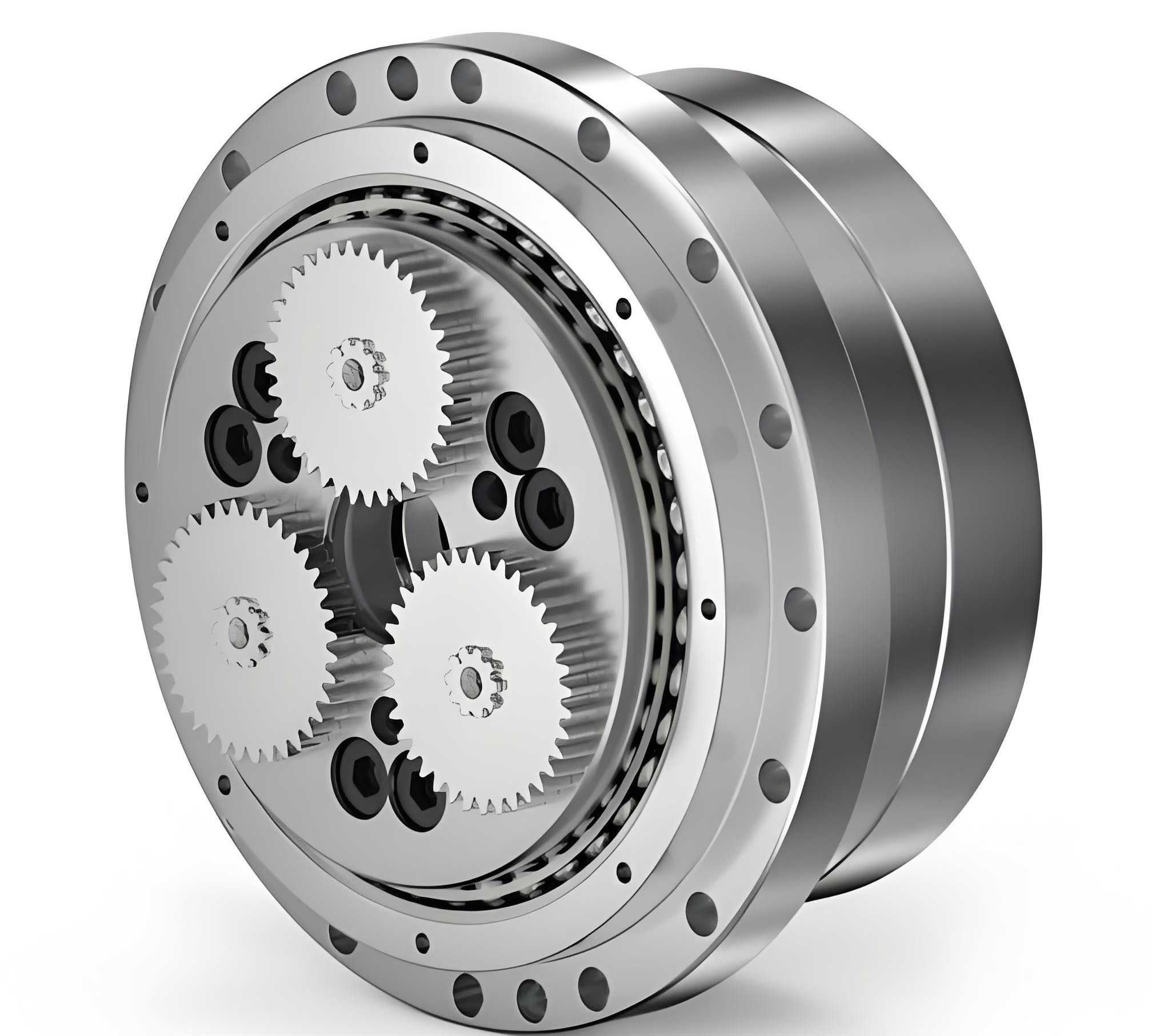
The operational principle of a standard rotary vector reducer is based on a two-stage reduction mechanism. The first stage typically consists of a planetary gear train with involute gears. The input rotation drives the sun gear, which meshes with multiple planetary gears. These planetary gears rotate within a fixed gear ring or a carrier. The second, and most critical, stage is the cycloidal-pin wheel mechanism. The planetary gears are mounted on eccentric crankshafts (also called曲柄轴). As the planetary gears revolve, they impart an eccentric motion to these crankshafts. A cycloidal disk (摆线轮), mounted on the eccentric portion of each crankshaft, engages with a ring of stationary pin wheels (针轮). The eccentric motion causes the cycloidal disk to undergo a compound movement, resulting in a high reduction ratio. The output is taken from the carrier connected to the cycloidal disks. The final output speed is significantly lower than the input speed, with the major reduction occurring in the cycloidal stage. The kinematic relationship defining the reduction ratio, \( i \), of a standard rotary vector reducer is given by:
$$ i = 1 + \frac{Z_p}{Z_c} $$
where \( Z_p \) is the number of pins in the pin wheel and \( Z_c \) is the number of lobes (teeth) on the cycloidal disk. This fundamental design grants the rotary vector reducer its exceptional characteristics, but achieving the stringent accuracy requirements (often below 1.5 arc-min for backlash and 1.0 arc-min for transmission error) demands meticulous attention to detail in every aspect of its production.
Cycloidal Gear Tooth Profile Modification: Theory and Methodology
The heart of a rotary vector reducer’s precision lies in the design and manufacturing of the cycloidal disk. In theory, a perfect cycloidal profile generated by a rolling circle without slippage would provide multi-tooth simultaneous contact, ensuring high load capacity and stiffness. However, in practice, such an ideal profile is not feasible due to necessities for lubrication, assembly tolerances, and compensation for elastic deformations under load. Therefore, deliberate modification or “修形” of the theoretical cycloidal tooth profile is essential. The primary goals of modification are to ensure proper lubrication clearance, facilitate assembly, and optimize the load distribution among the contacting teeth to minimize elastic deformation-induced errors, thereby enhancing the longevity and accuracy of the rotary vector reducer.
There are three fundamental methods for modifying the theoretical cycloidal profile, each altering the meshing condition in a specific way. The choice and combination of these methods are crucial for optimizing the performance of the rotary vector reducer.
| Modification Method | Principle | Effect on Profile | Primary Purpose |
|---|---|---|---|
| Isometric Modification (等距修形) | Altering the radius of the generating (rolling) circle used to create the cycloidal profile. | Effectively changes the equidistant curve offset. Creates a uniform clearance around the entire tooth profile. | To provide general assembly and lubrication clearance. A foundational modification. |
| Profile Shift Modification (移距修形) | Shifting the center of the generating circle relative to the base circle of the pin wheel. | Systematically adjusts the tooth thickness, making teeth slightly thinner or thicker. | To control the initial meshing clearance (backlash) and fine-tune the contact pattern. |
| Turning Angle Modification (转角修形) | Introducing a slight phase shift or rotation to the cycloidal disk relative to its theoretical position. | Asymmetrically modifies the meshing points on the flank of the cycloidal tooth. | To compensate for specific elastic deformations (e.g., from crankshaft bending) and optimize load distribution among a fewer number of simultaneously meshing teeth. |
While modification is necessary, it inherently reduces the number of teeth in simultaneous contact. Under load, the cycloidal disk and the pins undergo elastic deformation. The two major sources of this deformation in a rotary vector reducer are: (1) the contact deformation at the interface between the cycloidal disk tooth flank and the pin, and (2) the contact deformation between the pin and the wall of its housing hole in the pin wheel plate. The combined effect of these deformations, along with the manufacturing imperfections, determines the actual load distribution.
To achieve optimal performance, the modification amount must be carefully calculated to balance backlash, load capacity, and stiffness. An optimal modification profile is often one that results in a load distribution where the maximum elastic deformation of the cycloidal tooth under design load is compensated by the intentional modification clearance. This state minimizes peak contact stress and ensures smoother torque transmission. The contact force \( F_i \) on the i-th pin and the corresponding deformation \( \delta_i \) can be modeled based on Hertzian contact theory and system compliance. The relationship is governed by the system’s stiffness matrix and the geometric conditions post-modification. The goal is to find a modification vector \( \mathbf{\Delta} = [\Delta_1, \Delta_2, …, \Delta_n] \) that minimizes the maximum contact force \( F_{max} \) or ensures a more uniform force distribution, subject to the constraint that the resulting backlash \( B \) is within the specified limit (e.g., 1.5 arc-min).
The total deformation \( \delta_{total, i} \) at a meshing point can be expressed as a sum:
$$ \delta_{total, i} = \delta_{Hertz, i} + \delta_{bending, i} + \Delta_i $$
where \( \delta_{Hertz, i} \) is the local contact deformation, \( \delta_{bending, i} \) is the structural deformation of the crankshaft and disk, and \( \Delta_i \) is the intentional modification clearance (which can be positive or negative). Sophisticated design software for a rotary vector reducer iteratively solves for the modification profile that creates a favorable \( \delta_{total, i} \) distribution under load.
Comprehensive Analysis of Factors Affecting Backlash (回差)
Backlash, defined as the lost motion or angular play between input and output when direction is reversed, is a critical accuracy metric for a rotary vector reducer. It is not a single error but an accumulation of clearances originating from various sources. These sources can be classified into three main categories: design and manufacturing errors, assembly errors, and operational errors (e.g., wear, temperature). For a newly assembled high-precision rotary vector reducer, the first two categories are the primary focus.
The total backlash \( B_{total} \) of the system can be conceptualized as the sum of contributions from both reduction stages, though the cycloidal stage is typically the dominant contributor due to its higher sensitivity.
$$ B_{total} \approx B_{planetary} + B_{cycloidal} $$
Where \( B_{planetary} \) is the backlash from the first-stage involute planetary gear train, and \( B_{cycloidal} \) is the backlash from the second-stage cycloid-pin mechanism. The sensitivity of each stage’s backlash to component errors differs significantly.
1. First-Stage (Planetary Gear) Backlash Sensitivity
Errors in the involute gear stage generally have a lower sensitivity coefficient on the final output backlash of the rotary vector reducer. This is because the planetary stage’s reduction ratio amplifies input errors but is itself a smaller portion of the total ratio. Key error sources include:
- Center Distance Error (\( \Delta a \)): Deviation in the distance between sun gear and planetary gear centers.
- Tooth Thickness Error (\( \Delta S \)): Variations in the actual tooth thickness of sun, planet, or ring gears from their nominal values.
- Run-out Errors: Eccentricity of gears or the planet carrier.
Due to the lower sensitivity, manufacturing tolerances for these components can be slightly relaxed compared to the cycloidal components without drastically impacting the final rotary vector reducer backlash. For example, the tolerance on the gear’s chordal tooth thickness or base tangent length can be in a larger ISO tolerance grade.
2. Second-Stage (Cycloidal-Pin) Backlash Sensitivity
This stage is extremely sensitive to geometric errors. Even micron-level deviations can translate into measurable arc-minute changes in output backlash. The major error contributors and their effects are summarized below:
| Error Source | Description | Direct Effect on Cycloidal Mesh | Sensitivity to Backlash |
|---|---|---|---|
| Pin Position Error (\( \Delta r_p \)) | Radial or angular deviation of a pin from its nominal position on the pitch circle of the pin wheel. | Alters the effective center distance for specific teeth, creating non-uniform clearance. | Very High. A systematic radial error directly translates into backlash. |
| Cycloid Disk Profile Error (\( \Delta \rho \)) | Deviation of the actual machined cycloidal lobe from its designed (modified) profile. | Creates local interference or excessive clearance at specific meshing points. | Very High. Directly defines the mating surface. |
| Crankshaft Eccentricity Error (\( \Delta e \)) | Error in the eccentric distance of the crankshafts that carry the cycloidal disks. | Affects the kinematic motion of the cycloidal disk, altering the meshing phase and effective center distance. | High. Impacts the fundamental rolling motion. |
| Bearing Clearance (\( \delta_{bearing} \)) | Radial and axial play in the support bearings for the crankshafts and output carrier. | Allows small relative displacements between components, contributing to lost motion. | High. A direct source of mechanical play. |
| Pin-to-House Clearance (\( \delta_{pin} \)) | Clearance between the pin diameter and the diameter of its housing hole in the pin wheel plate. | Allows the pin to “float” slightly, absorbing some of the cycloidal disk’s force but also adding compliance. | Medium-High. Managed carefully to allow pin rotation for lubrication but minimize wobble. |
The combined backlash from the cycloidal stage \( B_{cycloidal} \) can be modeled as a function of these key errors. A simplified analytical model considering the most sensitive parameters—pin position error and the designed modification—can be expressed as:
$$ B_{cycloidal} \approx \frac{2 \cdot \max(|\Delta r_p|) + \Delta_{mod}}{r_p} \cdot \frac{180 \times 60}{\pi} \text{ (arc-min)} $$
where \( \max(|\Delta r_p|) \) is the maximum absolute radial pin position error, \( \Delta_{mod} \) is the equivalent radial clearance intentionally created by the tooth profile modification (a function of isometric and profile shift amounts), and \( r_p \) is the nominal pin wheel pitch radius. This formula highlights why controlling pin position tolerance is paramount in manufacturing a high-precision rotary vector reducer.
Strategies for Controlling and Enhancing Transmission Accuracy
To produce a rotary vector reducer that meets the demanding precision standards of modern robotics, a holistic approach encompassing design optimization, precision manufacturing, meticulous assembly, and rigorous testing is required.
1. Design Phase Optimization
- Optimal Modification Synthesis: Utilize advanced multi-body dynamics and finite element analysis (FEA) software to simulate the loaded state of the rotary vector reducer. The goal is to synthesize a combined modification profile (isometric + shift + turning angle) that optimally compensates for the calculated elastic deformations of the crankshaft, cycloidal disk, and housing. This “loaded tooth contact analysis” ensures the best possible load distribution and minimal transmission error under operating conditions.
- Tolerance Allocation Based on Sensitivity: Perform a tolerance sensitivity analysis to allocate stricter manufacturing tolerances to parameters with high sensitivity (like pin position and cycloid profile) and more relaxed tolerances to low-sensitivity parameters. This balances cost and performance effectively.
- Preload Design: Incorporate a controlled preload mechanism, often via selected bearings or adjustable elements, to eliminate bearing clearance—a significant contributor to backlash. Proper preload minimizes lost motion without causing excessive friction or reducing bearing life.
2. Precision Manufacturing and Metrology
- High-Precision Machining of Cycloidal Disks: Employ state-of-the-art CNC grinding machines with sub-micron positioning accuracy to produce the cycloidal profile. The grinding wheel profile must be precisely dressed according to the modified design data. In-process gauging and post-process coordinate measuring machine (CMM) inspection are mandatory to verify profile accuracy, lobe spacing, and eccentricity.
- Ultra-Precise Pin Wheel Manufacturing: The pin holes on the pin wheel plate must be machined with extreme positional accuracy. Processes like coordinate boring, precision jig boring, or even photochemical machining for very high pin counts are used. The circularity, diameter, and positional tolerance (often within a few microns) of these holes are critical for the performance of the rotary vector reducer.
- Crankshaft Precision: The eccentric journals on the crankshaft must be ground to high precision, with strict control over the eccentricity value, phase angle between journals (for multi-disk designs), and concentricity of the bearing journals.
3. Controlled Assembly Process
- Clean Room Environment: Assemble the rotary vector reducer in a clean, temperature-controlled environment to prevent contamination from dust or chips, which can affect fit and cause premature wear.
- Selective Assembly: For ultimate precision, components can be measured and grouped into selective bins based on their actual dimensions (e.g., pin hole size, cycloid disk effective size). Components are then matched from specific bins to achieve a target pre-defined clearance or preload, minimizing the variation in final backlash between units.
- Precise Bearing Mounting: Use proper tools and thermal fitting techniques to mount bearings without inducing additional preload or damage. Verify run-out after assembly.
- Backlash Measurement and Adjustment: Integrate a final backlash measurement station in the assembly line. For some designs, a slight final adjustment (e.g., via a shim or a threaded adjustment ring on the pin wheel) might be possible to bring the backlash within the tightest specification.
4. Quality Verification and Life Testing
- Comprehensive Performance Testing: Every high-end rotary vector reducer should undergo a test cycle measuring:
- Static Backlash: Using a precision torque actuator and angular encoder.
- Transmission Error: Measuring the difference between the theoretical and actual output position during slow, continuous rotation under light load.
- Torsional Stiffness: Applying a gradually increasing torque and measuring the angular deflection.
- Running-in and Efficiency Test: Running the unit under load for a period to seat the components and measure operational efficiency and temperature rise.
- Accelerated Life Testing (ALT): Sample units from production batches should undergo ALT under high load and stress conditions to predict long-term wear characteristics and verify the durability of the design and lubrication system.
Conclusion
The pursuit of higher transmission accuracy in rotary vector reducers is a multifaceted engineering challenge that sits at the intersection of theoretical mechanics, precision manufacturing, and meticulous assembly practice. The cycloidal gear modification is not merely a compensation for manufacturing imperfections but a proactive design tool to optimize load sharing and stiffness under real operating conditions. The control of backlash, a key precision indicator, requires a deep understanding of error sensitivity, leading to intelligent tolerance allocation and stringent control over the machining of critical components like the pin wheel and cycloidal disk. By adopting a systems engineering approach—from optimized design synthesis and ultra-precision machining to controlled assembly and rigorous testing—manufacturers can consistently produce rotary vector reducers that meet the ever-increasing demands for precision, reliability, and longevity in advanced robotic and automation applications. The continuous improvement in these areas is essential for advancing the capabilities of industrial robotics and high-precision motion systems.