
This work presents a comprehensive methodology for establishing a dynamic model of the Rotary Vector (RV) reducer, a critical precision component in robotic joints and automation systems. The objective is to develop a mathematical framework capable of analyzing its frequency characteristics and vibration behavior, which is essential for mitigating resonance-induced issues like robot arm judder. The modeling approach systematically integrates the dynamics of its two primary transmission stages: the first-stage involute spur gear train and the second-stage cycloid-pin wheel planetary mechanism.
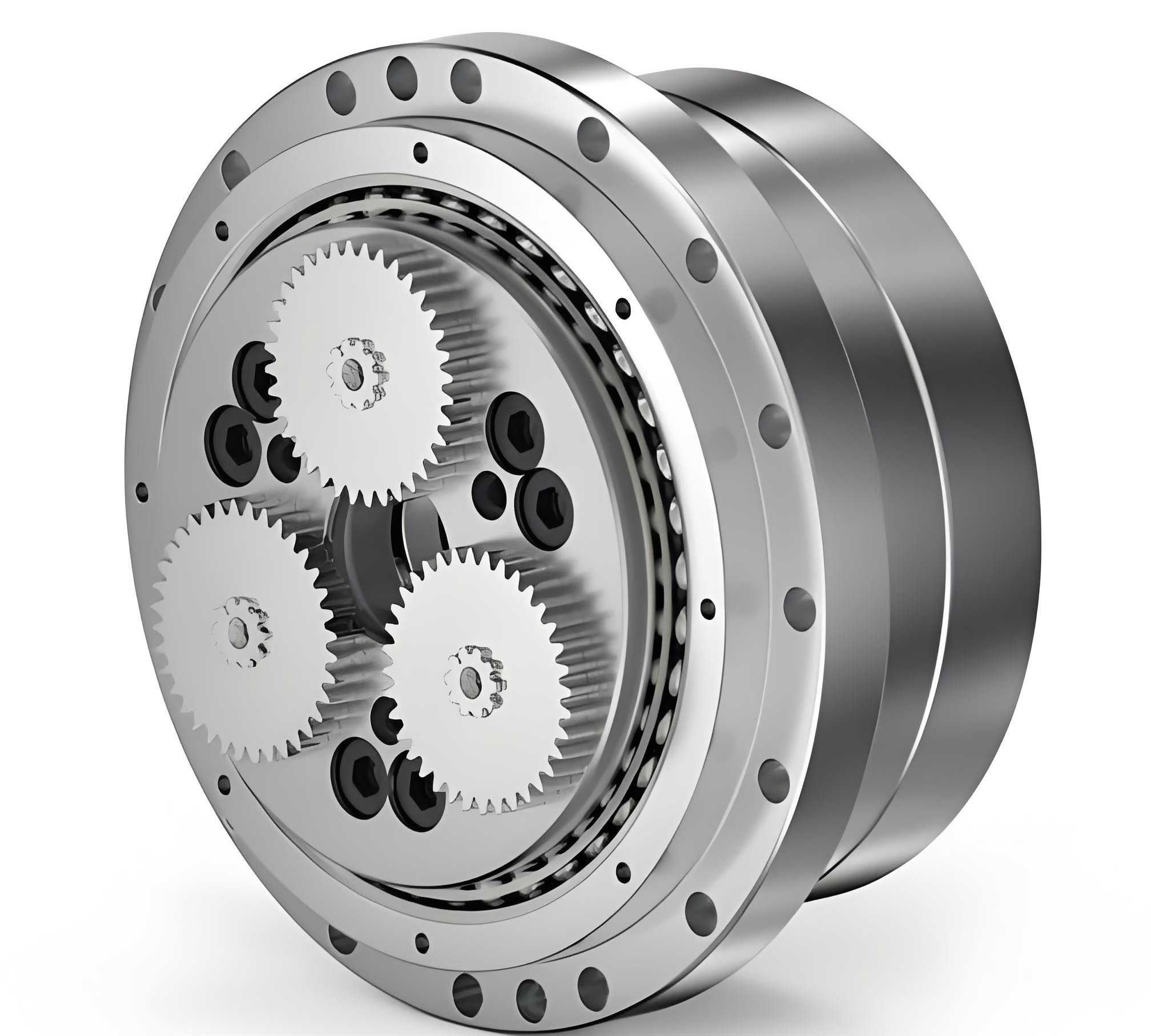
The Rotary Vector reducer exemplifies an advanced compact drive solution. Its superior performance characteristics, such as high reduction ratio, torsional stiffness, load capacity, and smooth operation with low backlash, stem from its unique two-stage design. The first stage consists of a conventional planetary gear train with involute teeth, providing an initial speed reduction. The second, and defining, stage is a cycloidal drive where the motion of the crankshaft (connected to the first-stage planet carrier) drives cycloid disks that mesh with a stationary ring of pins. This combination yields remarkable compactness and robustness.
The dynamic performance of a Rotary Vector reducer is paramount for high-precision applications. Transmitted torque fluctuations, manufacturing errors, and time-varying meshing stiffness can excite structural resonances. Therefore, an accurate dynamic model, capturing the essential stiffness and inertia properties of the system, is indispensable for predictive design and noise/vibration analysis. The core challenge lies in accurately modeling the nonlinear, multi-tooth contact stiffness of the cycloid-pin interface, which forms the heart of the Rotary Vector reducer’s performance.
1. Force Analysis in the Cycloid-Pin Drive
The force transmission within the cycloid-pin stage is central to the dynamics of the Rotary Vector reducer. In the standard configuration, the crankshaft rotates clockwise, driving the cycloid disks in an epicyclic motion that results in a slow counter-clockwise rotation of the output flange. For analytical purposes, using the principle of inverse motion (fixing the output), the pins become the driving elements. The contact forces between the cycloid disk and the pins are distributed among several simultaneously engaged tooth pairs. Assuming pure rolling and neglecting friction, these forces act along the common normal at each contact point, directed towards the instantaneous center of motion.
To determine the magnitude of the force at the \(i\)-th contact point, \(F_i\), a static equilibrium analysis under an applied output torque \(T_v\) is performed. Considering two cycloid disks sharing the load (with a 10% safety factor for uneven distribution), the force is derived as:
$$F_i = \frac{2.2 T_v}{K_1 Z_g R_z} \frac{\sin \theta_{bi}}{\sqrt{S}}$$
where:
\(T_v\) = Resisting torque on the output shaft,
\(Z_g\) = Number of teeth on the cycloid disk,
\(R_z\) = Radius of the pin center circle,
\(K_1\) = Short-width coefficient (\(K_1 = r_b / R_z\), with \(r_b\) as the rolling circle radius),
\(\theta_{bi}\) = Angle between the line connecting pin center to rolling circle center and the force reference axis (y-axis),
\(S = 1 + K_1^2 – 2K_1 \cos \theta_{bi}\).
| Parameter | Symbol | Role in Force Calculation |
|---|---|---|
| Output Torque | \(T_v\) | Primary load input determining force magnitude. |
| Pin Circle Radius | \(R_z\) | Scales the force; larger radius reduces contact force for same torque. |
| Short-width Coefficient | \(K_1\) | Defines the tooth profile geometry and load distribution pattern. |
| Engagement Angle | \(\theta_{bi}\) | Determines the instantaneous direction and lever arm for each contact force. |
2. Geometric Foundation: Curvature of the Cycloid Profile
Accurate modeling of contact deformation in the Rotary Vector reducer requires knowledge of the local curvature of the cycloid tooth profile. The theoretical profile, derived from the generating principle, is given in parametric form:
$$
\begin{aligned}
x_0 &= R_z \left( \sin \psi’_b – \frac{K_1}{Z_b} \sin(Z_b \psi’_b) \right) \\
y_0 &= R_z \left( \cos \psi’_b – \frac{K_1}{Z_b} \cos(Z_b \psi’_b) \right)
\end{aligned}
$$
where \(Z_b\) is the number of pins and \(\psi’_b\) is the generation angle. The radius of curvature \(\rho_0\) at any point on this profile is obtained from differential geometry:
$$
\rho_0 = \frac{ \left[ \left( \frac{dx_0}{d\psi’_b} \right)^2 + \left( \frac{dy_0}{d\psi’_b} \right)^2 \right]^{3/2} }{ \frac{dx_0}{d\psi’_b} \frac{d^2 y_0}{d{\psi’_b}^2} – \frac{dy_0}{d\psi’_b} \frac{d^2 x_0}{d{\psi’_b}^2} }
$$
Evaluating the derivatives and simplifying with the substitution \(\theta_b = Z_b \psi’_b – \psi’_b\) yields the working formula:
$$
\rho_0 = \frac{ (1 + K_1^2 – 2K_1 \cos \theta_b)^{3/2} R_z }{ K_1 (1 + Z_b) \cos \theta_b – (1 + Z_b K_1^2) }
$$
The sign of \(\rho_0\) indicates concavity. For the actual tooth flank, which is an equidistant curve offset by the pin radius \(r_z\), the effective curvature radius \(\rho_b\) for contact mechanics is:
$$
\rho_b = \rho_0 + r_z
$$
This geometric parameter \(\rho_b\) is crucial for the subsequent stiffness calculation in the Rotary Vector reducer’s cycloid stage.
3. Dynamic Stiffness Model for the Cycloid-Pin Pair
The meshing stiffness of the cycloid-pin interface is the most critical and complex element in the dynamic model of the Rotary Vector reducer. The contact, though theoretically line contact, is treated as an elastic Hertzian contact patch under load.
3.1. Contact Deformation via Hertz Theory
For two elastic cylinders in contact, the total approach \(a\) (mutual compression) under force \(F_i\) is given by:
$$
a = \sqrt{ \frac{4 F_i}{\pi b} \frac{1-\nu^2}{E} \left( \frac{1}{\rho_1} + \frac{1}{\rho_2} \right)^{-1} }
$$
where \(b\) is the face width, \(E\) is Young’s modulus, \(\nu\) is Poisson’s ratio. For the Rotary Vector reducer’s cycloid-pin contact, the equivalent curvature is \(1/\rho_i = 1/r_z – 1/\rho_b\) (taking sign convention for convex surface). Assuming identical material for pin and cycloid disk:
$$
a = \sqrt{ \frac{8 F_i \rho_i (1-\nu^2)}{\pi b E} }
$$
Here, \(\rho_i = \left( \frac{1}{r_z} – \frac{1}{\rho_{bi}} \right)^{-1}\).
3.2. Radial Stiffness of Individual Elements
The contact deformation \(a\) manifests as radial deflection of both the pin and the cycloid tooth. Using geometry of the circular arc, the radial deflection of the pin \(\delta_{z}\) and the cycloid tooth \(\delta_{b}\) can be approximated for small \(a\) as:
$$
\delta_{z} \approx \frac{a^2}{2r_z} = \frac{4 F_i \rho_i (1-\nu^2)}{\pi b E r_z}, \quad \delta_{b} \approx \frac{a^2}{2\rho_b} = \frac{4 F_i \rho_i (1-\nu^2)}{\pi b E \rho_{bi}}
$$
Thus, the individual radial stiffness values for the pin and cycloid tooth at the \(i\)-th contact are:
$$
K_{zi} = \frac{F_i}{\delta_{z}} = \frac{\pi b E r_z}{4 \rho_i (1-\nu^2)}, \quad K_{bi} = \frac{F_i}{\delta_{b}} = \frac{\pi b E \rho_{bi}}{4 \rho_i (1-\nu^2)}
$$
Substituting the expression for \(\rho_i\) and \(\rho_{bi}\) from Section 2, these can be expressed in terms of the fundamental design parameters \(R_z\), \(K_1\), \(r_z\), and angle \(\theta_b\).
3.3. Stiffness of a Single Contact Pair and the Complete Interface
The pin and cycloid tooth at a contact point act as springs in series. Therefore, the stiffness for a single meshing pair \(i\) is:
$$
K_{si} = \left( \frac{1}{K_{bi}} + \frac{1}{K_{zi}} \right)^{-1} = \frac{K_{bi} K_{zi}}{K_{bi} + K_{zi}} = \frac{\pi b E}{4(1-\nu^2)} \cdot \frac{r_z \rho_{bi}}{r_z + \rho_{bi}} \cdot \frac{1}{\rho_i}
$$
A more explicit form in terms of design parameters is:
$$
K_{si} = \frac{\pi b E R_z S^{3/2}}{4(1-\nu^2) \left[ R_z S^{3/2} + 2 r_z T \right]}, \quad \text{where } T = K_1 (1+Z_b) \cos \theta_b – (1+Z_b K_1^2)
$$
The total meshing stiffness \(K_{bz}\) for one cycloid disk is the sum of the stiffnesses of all \(n\) simultaneously engaged tooth pairs, adjusted by a factor \(\lambda\) (\(0 < \lambda \leq 1\)) accounting for manufacturing errors and load sharing imperfection:
$$
K_{bz} = \lambda \sum_{i=1}^{n} K_{si}
$$
In a Rotary Vector reducer, two cycloid disks phase-shifted by 180° engage with the full set of pins. While \(K_{si}\) varies slightly with \(\theta_b\), the combined stiffness \(K_{bz}\) of the entire interface can be considered approximately constant for simplified dynamic analysis, significantly contributing to the overall torsional rigidity of the Rotary Vector reducer.
| Stiffness Component | Expression | Physical Meaning |
|---|---|---|
| Single Pin Stiffness (\(K_{zi}\)) | \(\frac{\pi b E r_z}{4 \rho_i (1-\nu^2)}\) | Radial compliance of the pin (with sleeve) under contact load. |
| Single Cycloid Tooth Stiffness (\(K_{bi}\)) | \(\frac{\pi b E \rho_{bi}}{4 \rho_i (1-\nu^2)}\) | Bending/Local compression compliance of the cycloid tooth. |
| Single Pair Meshing Stiffness (\(K_{si}\)) | \(\frac{K_{bi} K_{zi}}{K_{bi} + K_{zi}}\) | Combined stiffness of one pin-cycloid contact point. |
| Total Cycloid-Pin Stiffness (\(K_{bz}\)) | \(\lambda \sum_{i=1}^{n} K_{si}\) | Aggregate torsional stiffness of the second-stage transmission in the Rotary Vector reducer. |
4. Dynamic Stiffness Model for the First-Stage Spur Gear Pair
The first-stage planetary gear train in a Rotary Vector reducer typically uses involute spur gears. Their meshing stiffness is time-varying due to the changing number of tooth pairs in contact (contact ratio) and the changing position of the contact point along the tooth profile. The Ishikawa formula provides a detailed method to model the tooth as a combination of a trapezoidal and a rectangular cantilever beam on a compliant foundation.
The total deflection \(\delta\) of a gear tooth at the load point along the line of action comprises four components:
$$
\delta = \delta_{Br} + \delta_{Bt} + \delta_S + \delta_G
$$
- Bending deflection of the rectangular part (\(\delta_{Br}\)):
$$ \delta_{Br} = \frac{12 F_N \cos^2 \alpha_x}{E b S_F^3} \left[ h_x h_r (h_x – h_r) + \frac{h_r^3}{3} \right] $$ - Bending deflection of the trapezoidal part (\(\delta_{Bt}\)):
$$ \delta_{Bt} = \frac{6 F_N \cos^2 \alpha_x}{E b S_F^3} \left[ \left( \frac{h_i – h_x}{h_i – h_r} \right)^4 – \frac{h_i – h_x}{h_i – h_r} – 2 \ln\left( \frac{h_i – h_x}{h_i – h_r} \right) – 3 \right] (h_i – h_r)^3 $$ - Shear deflection (\(\delta_S\)):
$$ \delta_S = \frac{2(1+\nu) F_N \cos^2 \alpha_x}{E b S_F} \left[ h_r + (h_i – h_r) \ln\left( \frac{h_i – h_r}{h_i – h_x} \right) \right] $$ - Deflection due to foundation compliance (\(\delta_G\)):
$$ \delta_G = \frac{24 F_N h_x^2 \cos^2 \alpha_x}{\pi E b S_F^2} $$
Where \(F_N\) is the normal load, \(b\) is face width, \(S_F\) is tooth thickness at root, \(h_r\), \(h_x\), \(h_i\) are distances from root, load point, and an imaginary apex to the tooth centerline, and \(\alpha_x\) is the pressure angle at the load point.
The total deflection \(\delta_{pair}\) for a meshing gear pair includes contributions from both driving and driven teeth, plus the Hertzian contact deflection \(\delta_{PV} = \frac{4(1-\nu^2)}{\pi E} \frac{F_N}{b}\):
$$
\delta_{pair} = \delta^{(1)} + \delta^{(2)} + \delta_{PV}
$$
Thus, the single tooth pair mesh stiffness \(K_s’\) is:
$$
K_s’ = \frac{F_N}{\delta_{pair}} = \left( \frac{1}{K^{(1)}} + \frac{1}{K^{(2)}} + \frac{1}{K_{PV}} \right)^{-1}
$$
where \(K^{(1)}, K^{(2)}\) are the individual tooth stiffnesses (each being the series combination of the four deflection components). For practical dynamic modeling of the Rotary Vector reducer, the average mesh stiffness is often used. Per ISO guidelines, the total mesh stiffness \(K_d\) for a spur gear pair can be approximated as:
$$
K_d = K_s’ (0.65 \epsilon_{\alpha} + 0.35)
$$
where \(\epsilon_{\alpha}\) is the transverse contact ratio. This \(K_d\) represents the effective torsional stiffness of the first-stage gear transmission in the Rotary Vector reducer model.
5. Integrated Torsional Dynamic Model of the Rotary Vector Reducer
Combining the stiffness models of both stages with the inertia of all rotating components allows the construction of a lumped-parameter torsional vibration model for the entire Rotary Vector reducer. A simplified 7-degree-of-freedom (DOF) model, assuming the pin housing (ring) is fixed, is highly effective. The DOFs are:
- \(\theta_1\): Rotation of input sun gear.
- \(\theta_2, \theta_3, \theta_4\): Rotation of three planet gears (assumed symmetric).
- \(\theta_5\): Rotation of the crankshaft/planet carrier (output of first stage, input to second).
- \(\theta_6\): Rotation of the cycloid disk(s) ensemble (relative motion).
- \(\theta_7\): Rotation of the output flange.
The system stiffness matrix \([K]_{7\times7}\) is derived from the potential energy, coupling the stages through the crankshaft (\(\theta_5\)). Key stiffness elements include:
- \(K_d\): First-stage spur gear mesh stiffness.
- \(K_{bz}\): Second-stage cycloid-pin mesh stiffness.
- \(K_{n1}\): Torsional stiffness of the shaft connecting planet gear to crankshaft.
- \(K_{n2}\): Torsional stiffness of the crankshaft between the two cycloid disks.
The resulting symmetric stiffness matrix for the Rotary Vector reducer is:
$$
[K] =
\begin{bmatrix}
3K_d R_1^2 & -K_d R_1 R_2 & -K_d R_1 R_2 & -K_d R_1 R_2 & 0 & 0 & 0 \\
-K_d R_1 R_2 & K_d R_2^2 + K_{n1} & 0 & 0 & -K_{n1} & 0 & 0 \\
-K_d R_1 R_2 & 0 & K_d R_2^2 + K_{n1} & 0 & -K_{n1} & 0 & 0 \\
-K_d R_1 R_2 & 0 & 0 & K_d R_2^2 + K_{n1} & -K_{n1} & 0 & 0 \\
0 & -K_{n1} & -K_{n1} & -K_{n1} & 3K_{n1}+3K_{n2}+K_{bz}(R_z-r_z)^2 & -3K_{n2} & -K_{bz}(R_z-r_z)^2 \\
0 & 0 & 0 & 0 & -3K_{n2} & 3K_{n2}+K_{bz}(R_z-r_z)^2 & -K_{bz}(R_z-r_z)^2 \\
0 & 0 & 0 & 0 & -K_{bz}(R_z-r_z)^2 & -K_{bz}(R_z-r_z)^2 & 2K_{bz}(R_z-r_z)^2
\end{bmatrix}
$$
Where \(R_1\), \(R_2\) are the pitch radii of the sun and planet gears, and \((R_z – r_z)\) is the effective arm for the cycloid-pin force converting to torque on the output.
The inertia matrix \([J]_{7\times7}\) is diagonal, containing the moments of inertia corresponding to each DOF: \(J_1, J_2, J_3, J_4, J_5, J_6, J_7\). Introducing a damping matrix \([C]_{7\times7}\) (often assumed proportional, e.g., Rayleigh damping), the free vibration equation of the Rotary Vector reducer system is:
$$
[J]\{\ddot{\theta}\} + [C]\{\dot{\theta}\} + [K]\{\theta\} = \{0\}
$$
For forced response analysis, such as studying the effect of input torque ripple, a forcing vector \(\{T(t)\}\) would be added to the right-hand side. The natural frequencies \(\omega_n\) and mode shapes are obtained by solving the undamped eigenvalue problem:
$$
\left( [K] – \omega_n^2 [J] \right) \{\Theta\} = \{0\}
$$
This model allows for the prediction of critical speeds and the assessment of the dynamic torque amplification within the Rotary Vector reducer under various operating conditions.
| Model Component | Key Parameters | Role in System Dynamics |
|---|---|---|
| First-Stage Gears | \(K_d, R_1, R_2, J_1, J_2\) | Provides initial speed reduction. Stiffness \(K_d\) influences high-frequency modes. |
| Crankshaft/Carrier | \(K_{n1}, K_{n2}, J_5\) | Couples the two stages. Its stiffness and inertia are pivotal for mid-frequency dynamics. |
| Cycloid-Pin Stage | \(K_{bz}, (R_z-r_z), J_6, J_7\) | Primary source of high torsional stiffness and low-speed output. Dominates the fundamental natural frequency of the Rotary Vector reducer. |
| Output Flange | \(J_7\) | Load-side inertia. Its magnitude affects the frequency of the dominant rigid-body mode. |
6. Conclusion
This article has detailed a systematic methodology for developing a dynamic model of the Rotary Vector reducer. The process begins with a static force analysis of the cycloid-pin transmission, followed by the derivation of the tooth profile curvature essential for contact mechanics. The core of the model lies in applying Hertzian contact theory to establish a stiffness formulation for the multi-tooth engagement of the cycloid stage. Complementarily, the Ishikawa beam theory is employed to model the time-averaged meshing stiffness of the first-stage spur gears. Finally, these component models are integrated into a lumped-parameter, multi-degree-of-freedom torsional vibration model, culminating in the system’s stiffness and mass matrices and its governing equation of motion.
The resulting model provides a powerful analytical tool for the design and analysis of the Rotary Vector reducer. It enables the prediction of natural frequencies and mode shapes, which is critical for avoiding resonance during operation—a common cause of vibration and positioning error in robotic systems. Furthermore, the model can be extended to include nonlinearities such as backlash in the gears, time-varying mesh stiffness of the spur gears, and more detailed contact loss models in the cycloid drive. Sensitivity analysis using this model can guide the optimization of key parameters like the short-width coefficient \(K_1\), pin radius \(r_z\), and component stiffness to achieve desired dynamic performance targets for the Rotary Vector reducer, ensuring high precision, low vibration, and long operational life in demanding applications.