
As a researcher deeply immersed in the field of precision transmission systems, I have dedicated significant effort to understanding the intricate mechanics of the rotary vector reducer, a critical component in robotics and heavy-duty machinery. The rotary vector reducer, often abbreviated as RV reducer, is renowned for its high transmission efficiency, compact size, and ability to handle substantial torque loads. In this article, I will elaborate on the fundamental principles, force analysis, and parameter optimization of rotary vector reducers, drawing from extensive study and computational modeling. The goal is to provide a thorough exposition that leverages formulas and tables to summarize key findings, while repeatedly emphasizing the importance of the rotary vector reducer in advanced engineering applications.
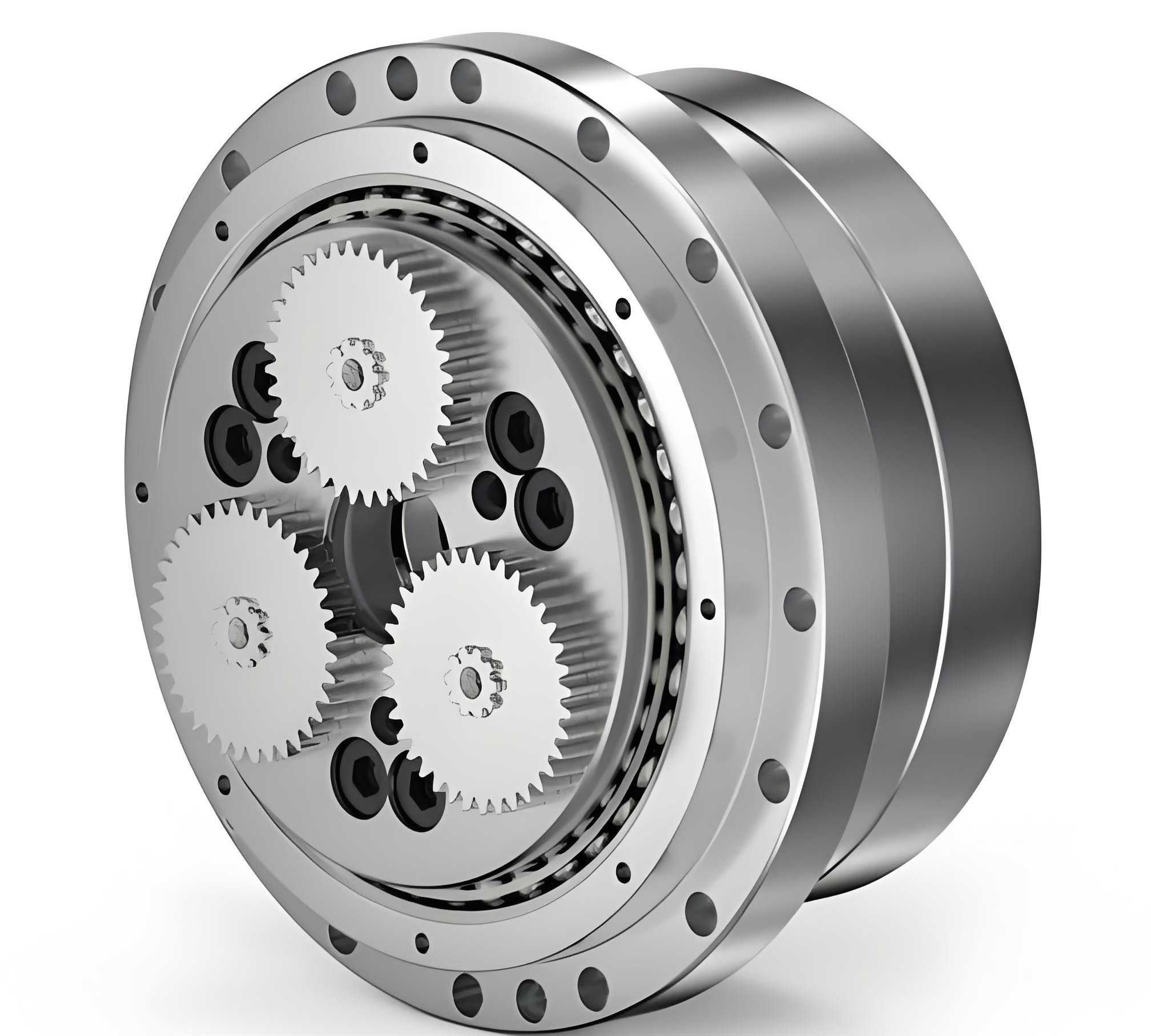
The rotary vector reducer features a two-stage reduction mechanism: the first stage consists of an involute spur gear transmission, and the second stage employs a cycloidal pin gear system. This design ensures smooth operation and high precision, making it ideal for industrial robots. However, the complex manufacturing processes and proprietary technologies have limited widespread adoption, prompting in-depth research into its dynamics. My analysis begins with a simplified structural model, as illustrated in the diagram below, which highlights the key components such as the input shaft, planetary gears, cycloidal gears, crankshafts, and output shaft.
To understand the performance of a rotary vector reducer, it is essential to derive its reduction ratio. Using the principle of gear meshing and a relative motion approach, I analyzed the kinematic relationships. Consider a rotary vector reducer with an input shaft (component 1), planetary gears (component 2), cycloidal gears (component 3), and an output shaft (component 5). The cycloidal gears are connected to the output shaft via a “W mechanism,” ensuring that the absolute angular velocity of the cycloidal gears equals that of the output shaft. From velocity relationships at points A and B, the reduction ratio can be expressed as follows:
At point A, the velocity equation is:
$$ \omega_5 (b + c) + \omega_{2r5} b = -\omega_3 a $$
where \(\omega_5\) is the angular velocity of the output shaft, \(\omega_{2r5}\) is the relative angular velocity of the crankshaft and planetary gear assembly with respect to the output shaft, \(\omega_3\) is the angular velocity of the cycloidal gear, and \(a\), \(b\), \(c\) are geometric distances. Since \(\omega_3 = \omega_5\), this simplifies to:
$$ \omega_5 (b + c) + \omega_{2r5} b = -\omega_5 a $$
Rearranging terms gives:
$$ \omega_{2r5} b = -\omega_5 (a + b + c) $$
At point B, the velocity equation is:
$$ \omega_5 R_1 – \omega_{2r5} R_2 = \omega_1 R_1 $$
where \(\omega_1\) is the angular velocity of the input shaft, \(R_1\) is the radius of the input gear, and \(R_2\) is the radius of the planetary gear. Substituting \(\omega_{2r5}\) from the previous equation, we derive the reduction ratio \(i = \omega_1 / \omega_5\):
$$ i = 1 + \frac{R_2 R_6}{(R_6 – R_3) R_1} $$
Here, \(R_6\) is the radius of the pin wheel, and \(R_3\) is the radius of the cycloidal gear. Using gear tooth numbers, where \(Z_1\), \(Z_2\), \(Z_3\), and \(Z_6\) represent the teeth counts of the input gear, planetary gear, cycloidal gear, and pin wheel respectively, and noting that \(R_3 / R_6 = Z_3 / Z_6\) and \(R_2 / R_1 = Z_2 / Z_1\), the reduction ratio becomes:
$$ i = 1 + \frac{Z_6 \cdot Z_2}{Z_6 Z_1 – Z_1 Z_3} $$
For a typical rotary vector reducer model, such as the RV-40E, with parameters \(Z_6 = 40\), \(Z_1 = 10\), \(Z_2 = 26\), and \(Z_3 = 39\), the reduction ratio calculates to:
$$ i = 1 + \frac{40 \times 26}{40 \times 10 – 10 \times 39} = 105 $$
This high reduction ratio exemplifies the efficiency of rotary vector reducers in applications requiring significant speed reduction. The derivation underscores the importance of geometric parameters in designing these systems.
Next, I delve into the force analysis during meshing between the cycloidal gear and the pin teeth. In rotary vector reducers, the pin teeth often lack sleeves, which alters the contact dynamics compared to traditional cycloidal drives. The force distribution depends on initial gaps due to gear modifications and elastic deformations. The initial gap \(\Delta(\varphi_i)\) in the normal direction for the \(i\)-th pin tooth is given by:
$$ \Delta(\varphi_i) = a \frac{1 – k \cos \varphi_i – \sqrt{1 – k^2} \sin \varphi_i}{\sqrt{1 + k^2 – 2k \cos \varphi_i}} + b \left(1 – \frac{\sin \varphi_i}{\sqrt{1 + k^2 – 2k \cos \varphi_i}}\right) $$
where \(\varphi_i\) is the angle of the \(i\)-th pin tooth relative to the carrier, \(k\) is the shortening coefficient (\(k = e z_p / r_z\)), \(e\) is the eccentricity of the crankshaft, \(z_p\) is the number of pin teeth, \(r_z\) is the radius of the pin center circle, \(a\) is the profile shift modification, and \(b\) is the equidistant modification. For the RV-40E reducer, key parameters include: pin center circle radius \(r_z = 64 \, \text{mm}\), pin radius \(r_{rp} = 3 \, \text{mm}\), pin wheel inner radius \(r_p = 70 \, \text{mm}\), eccentricity \(e = 1.3 \, \text{mm}\), pin tooth number \(z_p = 40\), cycloidal gear tooth number \(z_c = 39\), and modification values \(a = 0.008 \, \text{mm}\), \(b = -0.002 \, \text{mm}\). The shortening coefficient is \(k = e z_p / r_z = 0.8125\).
Under load, elastic deformations occur at two interfaces: the contact between the cycloidal gear tooth and the pin tooth, and the contact between the pin tooth and the pin wheel housing. The total deformation \(\omega = \omega_1 + \omega_2\) must exceed the initial gap for meshing to occur. Using Hertzian contact theory, the deformation for a cylinder-cylinder contact of length \(L\) is:
$$ \omega = \frac{2F}{\pi L} \left[ \frac{1 – \mu_1^2}{E_1} \left( \frac{1}{3} + \ln \frac{4R_1}{b} \right) + \frac{1 – \mu_2^2}{E_2} \left( \frac{1}{3} + \ln \frac{4R_2}{b} \right) \right] $$
where \(F\) is the force, \(E_1, E_2\) are elastic moduli, \(\mu_1, \mu_2\) are Poisson’s ratios, \(R_1, R_2\) are radii, and \(b\) is the half-width of the contact area given by:
$$ b = 1.60 \sqrt{\frac{F}{L} K_D \left( \frac{1 – \mu_1^2}{E_1} + \frac{1 – \mu_2^2}{E_2} \right)} $$
The equivalent curvature radius \(K_D\) depends on the contact type: for convex-convex contact (cycloidal gear and pin tooth):
$$ K_D = \frac{2 R_1 R_2}{R_1 + R_2} $$
and for convex-concave contact (pin tooth and housing):
$$ K_D = \frac{2 R_1 R_2}{R_2 – R_1} $$
The curvature radius of the cycloidal gear tooth profile is:
$$ \rho_0 = \frac{(r_z + a)(1 + k^2 – 2k \cos \varphi_i)^{3/2}}{k(z_p + 1) \cos \varphi_i – (1 + z_p k^2)} + (r_{rp} + b) $$
Thus, for the cycloidal gear-pin tooth contact, \(K_D = 2 \rho_0 r_{rp} / (\rho_0 + r_{rp})\), and for the pin tooth-housing contact, \(K_D = 2 r_p r_{rp} / (r_p – r_{rp})\). The deformation \(\delta_i\) in the normal direction for the \(i\)-th tooth is:
$$ \delta_i = l_i \beta = l_i \frac{\delta_{\text{max}}}{l_{\text{max}}} = \frac{l_i}{r’_c} \delta_{\text{max}} = \frac{\sin \varphi_i}{\sqrt{1 + k^2 – 2k \cos \varphi_i}} \delta_{\text{max}} $$
where \(l_i\) is the distance from the meshing point to the cycloidal gear center, \(r’_c = e z_c\) is the pitch radius, and \(\delta_{\text{max}}\) is the maximum deformation. Meshing occurs if \(\delta_i – \Delta(\varphi_i) > 0\), and the meshing force \(F_i\) is:
$$ F_i = \frac{\delta_i – \Delta(\varphi_i)}{\omega_{\text{max}}} F_{\text{max}} $$
The maximum force \(F_{\text{max}}\) is determined iteratively from the torque balance. For a single cycloidal gear transmitting torque \(T_c = 0.55 T\), where \(T\) is the output torque, the initial estimate is:
$$ F_{\text{max}0} = \frac{F_1 + F_2}{2} $$
with \(F_1 = 4 T_c k z_c / r_z\) and \(F_2 = 0.55 T / (e z_c)\). Through iteration, the actual \(F_{\text{max}}\) is found. For the RV-40E reducer with \(T = 572 \, \text{N·m}\), output speed \(5 \, \text{r/min}\), and cycloidal gear thickness \(b_c = 8.86 \, \text{mm}\), the meshing involves teeth 2 through 11, with maximum force \(F_{\text{max}} = 1190.8 \, \text{N}\) at the fourth pin tooth. The contact stress \(\sigma_H\) is calculated using:
$$ \sigma_H = 0.418 \sqrt{\frac{E_d F_i}{b_c p_{ei}}} $$
where \(E_d = 2 E_1 E_2 / (E_1 + E_2)\) is the equivalent elastic modulus, and \(p_{ei} = \rho_i r_{rp} / (\rho_i – r_{rp})\) is the equivalent curvature radius. The calculated meshing forces and contact stresses are summarized in Table 1.
| Tooth Number | Meshing Force (N) | Contact Stress (N/mm²) |
|---|---|---|
| 2 | 762.7 | 935.49 |
| 3 | 1107.7 | 1147.2 |
| 4 | 1190.8 | 1276.9 |
| 5 | 1151.5 | 1320.1 |
| 6 | 1046.2 | 1323.0 |
| 7 | 901.19 | 1290.8 |
| 8 | 730.54 | 1223.2 |
| 9 | 542.63 | 1114.4 |
| 10 | 343.07 | 948.16 |
| 11 | 135.90 | 657.27 |
The resultant forces on the cycloidal gear in the X and Y directions are obtained by summing the components:
$$ F_x = \sum_{i=m}^{n} F_i \cos \beta_i, \quad F_y = \sum_{i=m}^{n} F_i \sin \beta_i $$
where \(\tan \beta_i = (\cos(2\pi i / z_p) – k) / \sin(2\pi i / z_p)\). For the RV-40E, \(F_x = 7422.005 \, \text{N}\) and \(F_y = 1245.9 \, \text{N}\). This force analysis is crucial for assessing the structural integrity and performance of the rotary vector reducer.
To optimize the design of a rotary vector reducer, it is essential to evaluate how various parameters influence the transmission forces. I employ the osculating value method, a statistical technique for ranking influence degrees based on multiple criteria. The parameters considered include pin roller radius \(r_{rp}\), profile shift modification \(a\), equidistant modification \(b\), cycloidal gear thickness \(b_c\), and crankshaft eccentricity \(e\). The evaluation criteria are: change in resultant forces \(F_x\) and \(F_y\), original parameter value, material elastic modulus, and manufacturability (difficulty of implementation). The original data matrix is shown in Table 2.
| Parameter | \(F_x\) (N) | \(F_y\) (N) | Original Value (mm) | Elastic Modulus (N/m²) | Difficulty |
|---|---|---|---|---|---|
| Pin roller radius \(r_{rp}\) | 7421.9 | 1245.9 | 3 | 2.08e11 | 0.15 |
| Profile shift \(a\) | 7772.3 | 1238.2 | 0.008 | 2.07e11 | 0.25 |
| Equidistant \(b\) | 7123.7 | 1242.2 | 0.002 | 2.07e11 | 0.25 |
| Cycloidal gear thickness \(b_c\) | 7421.9 | 1245.9 | 8.86 | 2.07e11 | 0.15 |
| Crankshaft eccentricity \(e\) | 7412.9 | 1247.5 | 1.3 | 2.07e11 | 0.20 |
After standardizing the matrix, the best point set \(G\) and worst point set \(B\) are determined. The osculating value \(C\) for each parameter is calculated, with smaller \(C\) indicating closer proximity to the best point. The results are presented in Table 3.
| Parameter | Osculating Value \(C\) | Rank |
|---|---|---|
| Cycloidal gear thickness \(b_c\) | 0 | 1 |
| Pin roller radius \(r_{rp}\) | 2.6633 | 2 |
| Crankshaft eccentricity \(e\) | 3.4990 | 3 |
| Profile shift \(a\) | 4.0402 | 4 |
| Equidistant \(b\) | 4.0503 | 5 |
The analysis reveals that cycloidal gear thickness, pin roller radius, and crankshaft eccentricity are the most influential parameters on transmission forces in a rotary vector reducer. Therefore, in structural optimization, these should be prioritized as design variables to enhance performance and reliability.
In conclusion, the rotary vector reducer is a sophisticated transmission device that demands meticulous analysis for optimal design. Through kinematic modeling, I derived the reduction ratio using relative motion methods, providing a clear understanding of speed reduction mechanisms. The force analysis during meshing, considering elastic deformations and initial gaps, offers insights into load distribution and stress patterns, which are vital for durability assessments. Furthermore, the osculating value method effectively ranks parameter influences, guiding optimization efforts. The rotary vector reducer, with its high efficiency and compactness, remains indispensable in robotics, and continued research into its dynamics will further advance precision engineering. Future work could explore dynamic simulations, thermal effects, and advanced manufacturing techniques to push the boundaries of rotary vector reducer applications.
Throughout this discussion, I have emphasized the centrality of the rotary vector reducer in modern machinery. By integrating theoretical formulas, computational results, and statistical evaluations, this article aims to serve as a comprehensive resource for engineers and researchers dedicated to mastering the complexities of rotary vector reducers. The tables and equations provided summarize key data, facilitating practical implementation and further investigation into this critical technology.