
In my extensive experience with precision motion systems for industrial robotics, the pursuit of compact, stiff, and highly accurate power transmission components is paramount. Among these, the rotary vector reducer stands out as a cornerstone technology. Its unique two-stage architecture delivers exceptional torque density and positional accuracy, making it the preferred choice for robotic joint actuators. This document chronicles my systematic approach to the optimal design of a rotary vector reducer, focusing on achieving minimal overall volume while adhering to stringent performance constraints. The methodology involves a detailed theoretical analysis, simplification of complex constraints, and practical implementation using computational tools.
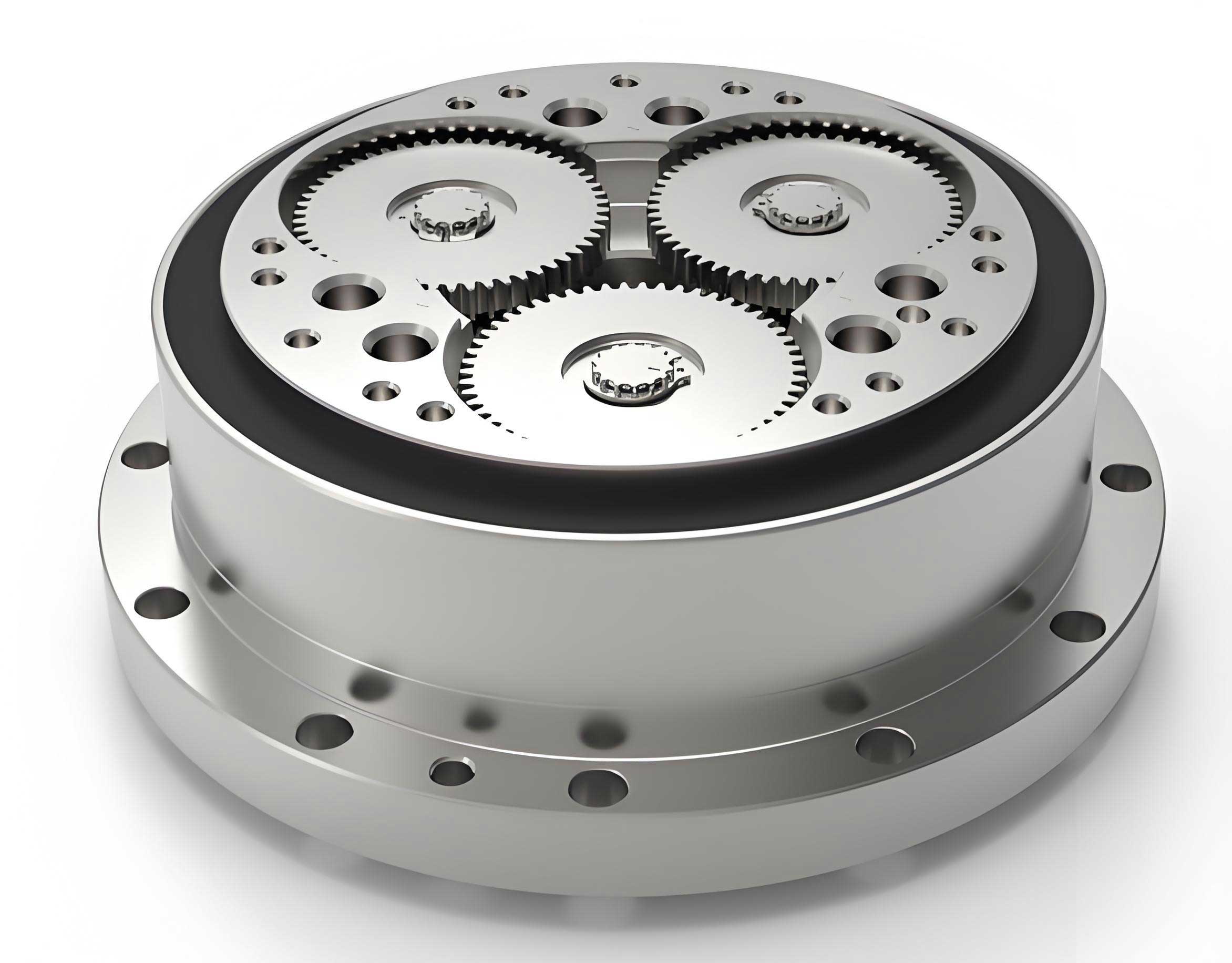
The architecture of the rotary vector reducer is ingeniously compact. It integrates two distinct reduction stages within a single housing. The first, high-speed stage is a conventional involute spur gear train. The input shaft, machined integrally with the central sun gear, drives two or three planetary gears arranged symmetrically. This stage provides the initial speed reduction. The second, low-speed stage is a cycloidal drive, which is the heart of the rotary vector reducer’s performance. The planetary gears are connected via splines to crankshafts. These crankshafts, supported by bearings in the planet carrier, drive two cycloidal disks through eccentric bearings. The cycloidal disks mesh with a ring of stationary pin gears housed in the pin wheel casing. The differential motion enforced by the fixed pins causes the cycloidal disks to rotate slowly relative to the crankshafts. This reverse rotation is transmitted back to the planet carrier, which serves as the final output member. This dual-stage design effectively combines the high-speed capability of gear trains with the superior load capacity and stiffness of cycloidal drives, making the modern rotary vector reducer so effective.
The operational principle is a fascinating interplay of motions. Input rotation is delivered to the sun gear. This drives the planetary gears, accomplishing the first-stage reduction. The rotation of each planetary gear is directly transferred to its corresponding crankshaft. The crankshaft’s rotation (now considered the input to the second stage) causes the cycloidal disks to undergo an eccentric “orbital” motion around the central axis. Because the pin gears are fixed, this orbital motion is constrained, forcing the cycloidal disks to also rotate on their own axes, but in the direction opposite to the crankshaft’s rotation. This self-rotation of the cycloidal disks, through the eccentric bearings, drives the planet carrier in the same direction as the original input. The total reduction ratio is the product of the first-stage gear ratio and the high-ratio cycloidal stage.
Design Specifications and Requirements
Designing a competitive rotary vector reducer necessitates balancing multiple, often conflicting, requirements. From my practice, the key specifications are:
- High Efficiency: Overall transmission efficiency must exceed 85% to minimize energy loss and heat generation.
- Minimal Backlash: For robotic applications requiring high positional repeatability, the angular backlash (or lost motion) must be tightly controlled, often within a few arc-minutes.
- Extended Service Life: The design life should meet or exceed typical industrial duty cycles, often demanding tens of thousands of hours of operation.
- Compactness and Light Weight: A primary optimization goal is to minimize the overall volume or mass while meeting all other criteria, directly impacting the robot’s payload capacity and dynamic performance.
- Ratio Distribution: The first-stage gear ratio should not be too low. The cycloidal stage offers superior load-bearing capacity and smoother torque transmission; therefore, the design should leverage this by allowing the cycloidal stage to handle a significant portion of the total reduction.
- Ratio Accuracy: The calculated total transmission ratio must be within ±5% of the target or nominal ratio.
- Geometric Constraint: The center distance of the first-stage gear pair should be between 50% and 60% of the pin wheel center circle radius in the cycloidal stage. This relationship is crucial for compact packaging and force distribution.
Material selection is critical to achieving these goals. High-hardness, wear-resistant materials with appropriate heat treatment are mandatory. A typical specification is summarized in the table below.
| Component | Material | Heat Treatment | Hardness (HRC) |
|---|---|---|---|
| Sun Gear & Planetary Gears | 20Cr / 20CrMnTi | Carburizing and Quenching | 58-62 |
| Cycloidal Disk | GCr15 / SH15 | Quenching and Tempering | 58-62 |
| Pin Gear | GCr15 | Quenching and Tempering | 58-62 |
| Crankshaft | 42CrMo | Quenching and Tempering | 28-32 |
Formulation of the Optimization Model
To systematically minimize the volume of the rotary vector reducer, I formulate a constrained nonlinear optimization problem. The core idea is to minimize the first-stage center distance, as it is a key driver of the overall package size and is directly linked to the second-stage dimensions via the geometric constraint.
Objective Function and Design Variables
The objective function is the center distance, \( a_0 \), of the first-stage planetary gear train:
$$ a_0 = \frac{m (z_1 + z_2)}{2} $$
where \( m \) is the module, \( z_1 \) is the number of teeth on the sun gear, and \( z_2 \) is the number of teeth on each planetary gear.
The primary independent design variables are therefore:
$$ \mathbf{X} = [m, z_1, z_2]^T $$
Additional parameters, such as the number of pin gears \( z_p \), become intermediate variables linked through constraints.
Constraint Conditions
The design must satisfy a comprehensive set of mechanical and geometric constraints.
1. Bending Fatigue Strength of Spur Gears:
The module must be sufficient to prevent tooth breakage under load.
$$ m \ge \sqrt[3]{\frac{2 K T_1 Y_{Fa} Y_{Sa}}{\psi_d z_1^2 [\sigma_F]}} $$
Here, \( K \) is the load factor, \( T_1 \) is the torque on the sun gear, \( Y_{Fa} \) and \( Y_{Sa} \) are the tooth form factor and stress correction factor (functions of \( z_1 \) and profile shift), \( \psi_d \) is the face width coefficient (typically 0.3-0.6 for planetary gears), and \( [\sigma_F] \) is the allowable bending stress. \( T_1 \) is derived from the input power \( P \) (kW), target output speed \( n_{out} \) (rpm), and total ratio \( i_{total} \):
$$ T_1 = 9.55 \times 10^6 \cdot \frac{P}{n_{out} \cdot i_{total}} \quad \text{(N·mm)} $$
$$ i_{total} = \left(1 + \frac{z_2}{z_1}\right) \cdot \frac{z_p}{z_p – 1} $$
2. Contact Fatigue Strength of Spur Gears:
The surface durability (pitting resistance) must be ensured.
$$ m z_1 \ge 2.32 \cdot \sqrt[3]{\frac{K T_1 (i_{12}+1) Z_E^2}{\psi_d i_{12}^2 [\sigma_H]^2}} $$
where \( i_{12} = z_2 / z_1 \) is the first-stage ratio, \( Z_E \) is the elasticity coefficient (189.9 \(\sqrt{\text{MPa}}\) for steel-steel), and \( [\sigma_H] \) is the allowable contact stress.
3. Transmission Ratio Accuracy:
The calculated total ratio must be close to the target ratio \( i_{req} \).
$$ \left| \frac{i_{total} – i_{req}}{i_{req}} \right| \le 0.05 $$
4. Gear Design Rules:
To avoid undercutting and ensure proper assembly in a multi-planet system:
$$ z_1 \ge z_{min} \quad \text{(typically 14-17 for 20° pressure angle)} $$
Furthermore, to balance the load between stages, the first-stage ratio should have a lower bound:
$$ i_{12} = \frac{z_2}{z_1} \ge 1.5 $$
5. Cycloidal Stage and Geometric Compatibility:
The central geometric constraint linking both stages is vital for a compact rotary vector reducer design.
$$ 0.5 R_p \le a_0 \le 0.6 R_p $$
where \( R_p \) is the radius of the pin center circle. \( R_p \) itself is sized based on the output torque \( T_{out} \):
$$ R_p = K_R \cdot \sqrt[3]{T_{out}} $$
where \( K_R \) is an empirical coefficient (0.85-1.3). The output torque is:
$$ T_{out} = 9.55 \times 10^6 \cdot \frac{P \cdot \eta_{total}}{n_{out}} $$
The total efficiency \( \eta_{total} \) can be estimated as the product of the stage efficiencies and bearing efficiencies, typically exceeding 0.85.
6. Cycloidal Disk Tooth Strength and Contact:
Additional constraints ensure the integrity of the cycloidal disk, a critical component in the rotary vector reducer. These include checks on tooth bending stress, contact stress with the pins, and the design of the eccentricity \( e \) and shortening factor \( K_1 \). The eccentricity is related to the reduction ratio and pin circle radius:
$$ e = \frac{R_p}{z_p} \cdot K_1 $$
where \( K_1 \) (typically 0.7-0.9) influences the tooth profile and contact conditions.
| Category | Mathematical Expression | Description |
|---|---|---|
| Objective | Minimize \( a_0 = \frac{m (z_1 + z_2)}{2} \) | Minimize first-stage center distance. |
| Constraints | \( m \ge \sqrt[3]{\frac{2 K T_1 Y_{Fa} Y_{Sa}}{\psi_d z_1^2 [\sigma_F]}} \) | Bending strength (Gear). |
| \( m z_1 \ge 2.32 \cdot \sqrt[3]{\frac{K T_1 (i_{12}+1) Z_E^2}{\psi_d i_{12}^2 [\sigma_H]^2}} \) | Contact strength (Gear). | |
| \( \left| (i_{total} – i_{req}) / i_{req} \right| \le 0.05 \) | Ratio accuracy. | |
| \( z_1 \ge 17, \quad i_{12} \ge 1.5 \) | Gear design rules. | |
| \( 0.5 R_p \le a_0 \le 0.6 R_p \) | Geometric compatibility. | |
| \( \sigma_{c,cycloidal} \le [\sigma_c], \quad \sigma_{b,cycloidal} \le [\sigma_b] \) | Cycloidal disk strength. | |
| Variables | \( m \) (std. series), \( z_1 \) (integer), \( z_2 \) (integer), \( z_p \) (integer) | Primary and linked discrete variables. |
Implementation and Design Example
Solving this mixed-integer nonlinear problem requires computational aid. I utilize a sequential approach to manage the complexity and discrete nature of variables like module and tooth counts. The process is implemented in a mathematical computing environment like MATLAB, using its `fmincon` solver for continuous sub-problems wrapped in logic to handle discrete choices.
Step 1: Parameter Initialization. Define inputs: Power \( P = 4.28 \text{ kW} \), Output Speed \( n_{out} = 5 \text{ rpm} \), Required Ratio \( i_{req} = 81 \).
Step 2: First-Stage Gear Optimization. For a range of standard module \( m \) values and feasible sun gear teeth \( z_1 \), solve for \( z_2 \) that meets the strength constraints (Eq. 1 & 2) and the ratio lower bound \( i_{12} \ge 1.5 \). Calculate the resulting center distance \( a_0 \).
Step 3: Cycloidal Stage Sizing. For each promising \( a_0 \) from Step 2, determine the required pin circle radius \( R_p = a_0 / 0.55 \) (using the mid-point of the 50-60% constraint). From \( R_p \) and the target total ratio \( i_{total} \approx i_{req} \), back-calculate the required number of pin gears \( z_p \) and the corresponding first-stage ratio. The total ratio is:
$$ i_{total} = \left(1 + \frac{z_2}{z_1}\right) \cdot \frac{z_p}{z_p – 1} $$
Iterate to find integer \( z_p \) that brings \( i_{total} \) closest to \( i_{req} \) within the 5% tolerance. Then calculate cycloidal disk parameters: eccentricity \( e = R_p / z_p \), tooth width, etc., and verify cycloidal disk stresses.
Step 4: Final Selection. Choose the combination \( (m, z_1, z_2, z_p) \) that results in the smallest valid \( a_0 \) while satisfying all constraints, including the final check on the geometric constraint \( 0.5R_p \le a_0 \le 0.6R_p \).
Applying this methodology to the RV-450E example, I obtain the following optimal parameters and compare them to a reference baseline design.
| Parameter | Symbol | Optimized Result | Reference Value | Unit | |
|---|---|---|---|---|---|
| Gear Module | \( m \) | 3.0 | 3.0 | mm | |
| Sun Gear Teeth | \( z_1 \) | 18 | 18 | – | |
| Planet Gear Teeth | \( z_2 \) | 35 | 38 | – | |
| First-Stage Center Distance | \( a_0 \) | 79.5 | 84.0 | mm | |
| First-Stage Ratio | \( i_{12} \) | 1.944 | 2.111 | – | |
| Number of Pin Gears | \( z_p \) | 42 | 38 | – | |
| Pin Circle Radius | \( R_p \) | 144.5* | 155.0 | mm | |
| Cycloidal Disk Teeth | \( z_c \) | 41 | 37 | – | |
| Total Transmission Ratio | \( i_{total} \) | 82.68 | 81.22 | – | |
| Ratio Error | – | 2.07% | 0.27% | – | |
| *Calculated from \( a_0 / 0.55 \) for geometric compatibility check. | |||||
The optimization successfully found a feasible design. The key achievement is the reduction of the first-stage center distance \( a_0 \) from 84.0 mm to 79.5 mm, a 5.4% decrease. This directly contributes to a more compact overall assembly for the rotary vector reducer. The optimized design shifts more of the total reduction to the cycloidal stage (\( z_p = 42 \) vs. 38), which is desirable given its high torque capacity. Both designs maintain the ratio error well within the 5% specification. This confirms the validity and effectiveness of the proposed optimization methodology for minimizing the size of a rotary vector reducer.
Conclusion
In this detailed exploration, I have presented a structured methodology for the optimal design of a rotary vector reducer with the primary objective of volume minimization. The process begins with a thorough understanding of the unique two-stage architecture and operational principles of the rotary vector reducer. Critical design requirements, from efficiency and backlash to life and compactness, are formalized into a mathematical optimization model. The core of the model minimizes the first-stage gear center distance subject to a system of constraints encompassing gear bending and contact fatigue, transmission ratio accuracy, geometric compatibility between stages, and cycloidal disk integrity. To manage computational complexity, a sequential solution strategy is employed, effectively handling the mixed-integer nature of the problem. A practical design example for an RV-450E type rotary vector reducer demonstrates the method’s efficacy, yielding a design with a smaller center distance than a referenced baseline while satisfying all performance constraints. This systematic approach provides a robust foundation for designing high-performance, compact rotary vector reducers essential for advanced robotic and precision motion systems.