
In the realm of advanced mechanical transmissions, hyperbolic gears represent a critical technology for power transfer between non-intersecting, non-parallel shafts, especially under extreme geometric constraints. These gears, characterized by their hyperbolic pitch surfaces, enable compact, efficient, and high-torque drives in aerospace, marine vessels, automotive systems, and robotics. My research focuses specifically on hyperbolic gears with small shaft angles—typically below 15 degrees—where traditional design and manufacturing approaches falter due to heightened sensitivity to errors, complex tooth flank generation, and challenges in achieving distortion-free, high-convergence surfaces. This article presents my comprehensive investigation into the geometric design, meshing behavior control, and manufacturing of such hyperbolic gears, employing extensive mathematical modeling, parametric analysis, and experimental validation.
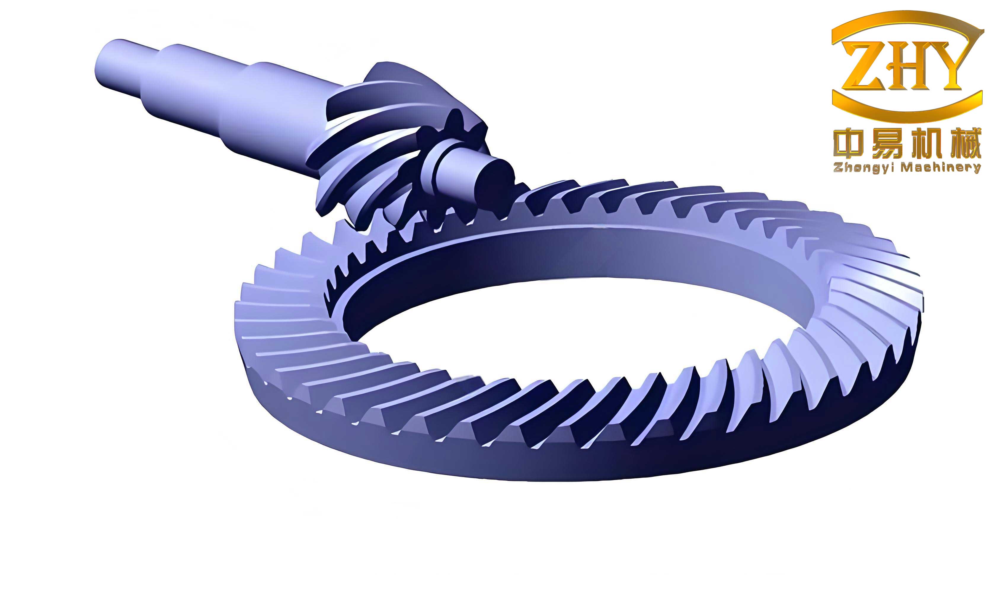
The image above depicts a typical hyperbolic gear pair, illustrating the intricate curvature and offset geometry that are fundamental to their operation. The complexity escalates when the shaft angle diminishes, necessitating novel methodologies to ensure reliable performance.
Fundamental Challenges in Small Shaft Angle Hyperbolic Gears
The deployment of hyperbolic gears in space-limited applications introduces three core scientific problems. First, the tooth profile evolution and meshing mechanics become exceedingly intricate as the shaft angle decreases, leading to unpredictable contact patterns and stress distributions. Second, there exists a inherent conflict between achieving low sensitivity to manufacturing/assembly errors and realizing an undistorted, highly convergent tooth surface—a paradox that conventional gear theory struggles to resolve. Third, standard tool design and machining techniques, developed for larger shaft angles, prove inadequate, often resulting in poor surface finish, premature wear, and noise. These issues collectively undermine efficiency, increase cost, and restrict installation flexibility, particularly in extreme-scale systems like aircraft engines or compact gearboxes.
Geometric Design Methodology: A Parametric Foundation
To address these challenges, I developed a geometric parameter design method that explicitly incorporates spatial pitch cone contact conditions. This approach ensures optimal load distribution and minimal edge contact from the outset. The fundamental parameters defining a hyperbolic gear pair include the shaft angle Σ, offset distance E, number of teeth on pinion (N_p) and gear (N_g), normal module m_n, pressure angle α, and spiral angle β. Their interrelationships are governed by kinematic and geometric constraints derived from the mating condition.
The basic kinematic relationship for hyperbolic gears, relating angular velocities, is:
$$ \frac{\omega_p}{\omega_g} = \frac{N_g}{N_p} = \frac{r_g}{r_p} $$
where ω denotes angular velocity and r the pitch radius. For small shaft angles, the pitch cone angles γ_p and γ_g are nearly equal, and their calculation must account for the offset. A more precise formulation involves the shaft angle and ratio:
$$ \tan \gamma_p = \frac{\sin \Sigma}{ \frac{N_g}{N_p} + \cos \Sigma } \quad \text{and} \quad \tan \gamma_g = \frac{\sin \Sigma}{ \frac{N_p}{N_g} + \cos \Sigma } $$
However, these classical formulas require modification when E is significant relative to pitch diameters. My model introduces correction factors based on the relative offset ratio ξ = E / (r_p + r_g). The effective pitch cone angles become:
$$ \gamma_p’ = \gamma_p + \Delta \gamma_p(\xi, \Sigma) \quad \text{and} \quad \gamma_g’ = \gamma_g + \Delta \gamma_g(\xi, \Sigma) $$
where Δγ are small-angle corrections derived from spatial trigonometry, ensuring true conjugate action.
The tooth flank geometry of a hyperbolic gear can be described parametrically. In a coordinate system attached to the gear, a point on the pinion tooth surface is given by:
$$ \mathbf{r}_p(u, \theta) = \begin{bmatrix} (R_p + u \cos \beta) \cos \theta + E \\ (R_p + u \cos \beta) \sin \theta \\ u \sin \beta – L_p \end{bmatrix} $$
Here, u is the parameter along the tooth length, θ is the rotational parameter, R_p is the reference cone distance, β is the mean spiral angle, and L_p is the pinion apex adjustment. A similar expression holds for the gear member. The surface normal vector, crucial for contact analysis, is:
$$ \mathbf{n}_p(u, \theta) = \frac{\partial \mathbf{r}_p}{\partial u} \times \frac{\partial \mathbf{r}_p}{\partial \theta} $$
To avoid undercutting, pointed teeth, or excessive sliding—common pitfalls in small-angle hyperbolic gears—I established a closed design parameter graph. This graph maps feasible combinations of key parameters that simultaneously satisfy strength, contact ratio, and manufacturability constraints. The table below summarizes the operational ranges and interdependencies for critical design variables in small shaft angle hyperbolic gears.
| Primary Parameter | Symbol | Typical Range (Small Σ) | Constraint Equations | Interaction with Other Parameters |
|---|---|---|---|---|
| Shaft Angle | Σ | 5° – 15° | Σ > Σ_min for avoidance of interference | Directly influences γ_p, γ_g and contact path curvature. |
| Offset Distance | E | 0.15D_g – 0.35D_g* | E ≤ E_max(Σ, N_p) for machining access | Higher E increases sliding but improves compactness. |
| Pinion Tooth Count | N_p | 12 – 25 | N_p ≥ N_p_min(Σ, β) to prevent undercut | Affects ratio, contact ratio, and root stress. |
| Gear Tooth Count | N_g | 25 – 50 | N_g / N_p ≈ 1.5 – 4.0 for balanced design | Determines speed reduction and overall size. |
| Normal Module | m_n | 2.0 – 6.0 mm | m_n selected based on bending strength (σ_F) | Larger m_n increases load capacity but reduces contact ratio. |
| Spiral Angle | β | 30° – 45° | β optimized for smooth engagement and axial thrust | Higher β improves overlap but raises axial forces. |
| Pressure Angle | α_n | 20° – 25° | α_n chosen per contact stress (σ_H) requirements | Larger α_n strengthens tooth but may increase noise. |
*D_g denotes the gear pitch diameter. The closed graph is a multi-dimensional plot ensuring that any chosen parameter set lies within a region free of geometric defects, derived by solving inequality sets from gear meshing theory.
Meshing Characteristics and Tooth Surface Topography Correlation
The performance of hyperbolic gears is dictated by the meshing characteristics—transmission error, contact pattern, load distribution, and stress field—which are intimately linked to the micro- and macro-geometry of the tooth flanks. I systematically investigated this correlation by modeling the loaded tooth contact analysis (LTCA) and simulating various surface topographies.
The unloaded transmission error (TE), a primary excitation source for vibration and noise, is computed from the deviation of the actual gear rotation from the ideal kinematic motion. For a hyperbolic gear pair, TE as a function of pinion rotation angle φ is:
$$ \text{TE}(\phi) = \phi_p – \frac{N_g}{N_p} \phi_g(\phi_p) $$
where φ_g is the gear rotation angle under perfect meshing condition. In practice, TE arises from tooth deflections and profile deviations. A key finding is that for small shaft angle hyperbolic gears, the sensitivity of TE to tooth flank form errors (like lead crowning or profile modification) is magnified. The relationship can be approximated by a sensitivity matrix:
$$ \Delta \text{TE} = \mathbf{S} \cdot \Delta \mathbf{X} $$
where ΔX is a vector of tooth surface coordinate deviations and S is the sensitivity matrix derived from the meshing equation.
The meshing equation itself, ensuring contact at any instant, is:
$$ \mathbf{n}_p \cdot \mathbf{v}_{pg} = 0 $$
with v_{pg} being the relative velocity vector between pinion and gear at the potential contact point. Solving this equation numerically across the tooth surface yields the contact path. For hyperbolic gears, the contact path is a spatial curve, and its stability is crucial. I derived that the curvature match between pinion and gear surfaces along this path, expressed via the induced normal curvature difference Δκ, must be minimized for low error sensitivity:
$$ \Delta \kappa = |\kappa_p^{(n)} – \kappa_g^{(n)}| $$
where κ_p^{(n)} and κ_g^{(n)} are the normal curvatures of the pinion and gear surfaces along the contact line direction. Small Δκ ensures a forgiving contact that tolerates misalignment without significant stress spikes.
To quantify the interplay between topography and performance, I conducted parametric studies, summarized in the table below. The table illustrates how specific tooth flank modifications—essential for small-angle hyperbolic gears—affect key meshing indicators.
| Topography Feature | Description & Mathematical Form* | Effect on Contact Pattern | Effect on Transmission Error Peak-to-Peak | Effect on Load Sharing Ratio | Recommended for Small Σ? |
|---|---|---|---|---|---|
| Linear Lead Crowning | Δz_l = C_l \cdot y^2, where y is lead coordinate | Broadens pattern, reduces edge contact | Reduction of 20-30% | Improves slightly | Yes, moderate |
| Profile Relief | Δx_p = C_p \cdot (x – x_0)^2, x profile coord. | Localizes pattern near center | Reduction of 15-25% | Can worsen if excessive | Yes, careful tuning |
| Bias-Modified (Elliptical) Crowning | Δz_b = C_{b1} y^2 + C_{b2} x y | Produces elliptical pattern, robust to misalignment | Reduction of 35-45% | Significant improvement | Highly recommended |
| Topography with Micro-ridges (Directed Lubrication) | Superimposed sinusoidal wave: A sin(2π y / λ) | Fragments pattern but improves lubrication | May increase slightly | Variable | For specialized applications |
| Fully Conformal (Logarithmic) Surface | z_c = K \ln(1 + a y^2) | Large, uniform contact area | Reduction of 40-50% | Optimal load sharing | Ideal but hard to manufacture |
*Coefficients C denote crowning magnitudes, tailored to gear size and load.
This analysis revealed that a bias-modified (elliptical) crowning, combined with slight profile relief, offers the best compromise for hyperbolic gears with small shaft angles, achieving low error sensitivity and high contact quality simultaneously.
Precision Forming Mechanism: Active Control of Meshing Behavior
Moving beyond passive design, I established a precision forming mechanism based on active control of the meshing behavior during the gear generation process. The core idea is to guide the cutting or grinding tool such that the resulting tooth surfaces exhibit desired contact characteristics directly, rather than through post-manufacturing corrections. This is achieved by formulating the gear generation as a controlled kinematic simulation of meshing.
In a typical face-milling process for hyperbolic gears, the tool (cutter head) and gear blank undergo a series of coordinated motions. The mathematical model treats the tool surface as a family of surfaces parameterized by machine settings. The equation of the generated gear surface is the envelope of the tool family. For a pinion, this is expressed as:
$$ \mathbf{R}_g(\theta, \phi, \psi) = \mathbf{M}_{bg}(\psi) \cdot \mathbf{M}_{tb}(\theta, \phi) \cdot \mathbf{r}_t $$
where r_t is a point on the tool surface, M_{tb} transforms from tool to blank coordinate system (functions of machine settings like cutter tilt θ and swivel ϕ), M_{bg} is the blank rotation matrix (angle ψ), and R_g is the resulting point on the gear. The envelope condition requires:
$$ \frac{\partial \mathbf{R}_g}{\partial \psi} \cdot \left( \frac{\partial \mathbf{R}_g}{\partial \theta} \times \frac{\partial \mathbf{R}_g}{\partial \phi} \right) = 0 $$
By actively controlling the machine settings (θ, ϕ) as functions of ψ, rather than keeping them constant, one can tailor the surface topography. I derived control laws that directly link these settings to target meshing properties. For instance, to impart a specific lead crowning C_l, the cutter tilt variation Δθ(ψ) is:
$$ \Delta \theta(\psi) = \frac{C_l \cdot r_c \cdot \sin(\beta)}{\partial f/\partial \theta} \cdot g(\psi) $$
Here, r_c is cutter radius, and g(ψ) is a shape function derived from the contact path geometry. This active control methodology ensures that the manufactured hyperbolic gear pair possesses pre-designed meshing behavior, effectively decoupling the design from limitations of standard tooling.
Manufacturing and Assembly: Error Compensation via Axial Micro-Adjustments
Even with optimal design and controlled manufacturing, assembly errors—such as axial misalignment, shaft offset deviations, and axis non-parallelism—can degrade the performance of hyperbolic gears. I developed a compensation method based on micro-adjustments of the axial positions of both the pinion and gear after initial assembly. This approach leverages the fact that small axial shifts can significantly alter the contact pattern and meshing phase, counteracting the effects of errors.
The relationship between assembly errors and required axial adjustments is modeled using influence coefficients. Let the assembly error vector be δ = [ΔE, ΔΣ, ΔA]^T, representing errors in offset, shaft angle, and axial position of the gear, respectively. The resulting changes in contact pattern location (ΔL, ΔW) and transmission error amplitude ΔTE are linearized for small errors:
$$ \begin{bmatrix} \Delta L \\ \Delta W \\ \Delta TE \end{bmatrix} = \mathbf{J} \cdot \begin{bmatrix} \Delta E \\ \Delta \Sigma \\ \Delta A \end{bmatrix} $$
where J is a 3×3 Jacobian matrix of influence coefficients, determined via computational simulation or experimental calibration for a specific hyperbolic gear design. To compensate, we introduce deliberate axial adjustments ΔA_p and ΔA_g for pinion and gear. The total effect of adjustments should negate the error effects:
$$ \mathbf{J}_A \cdot \begin{bmatrix} \Delta A_p \\ \Delta A_g \end{bmatrix} + \mathbf{J} \cdot \delta \approx \mathbf{0} $$
Here, J_A is the influence matrix for axial adjustments (a submatrix of J extended for both members). Solving this gives the optimal adjustments:
$$ \begin{bmatrix} \Delta A_p \\ \Delta A_g \end{bmatrix} = – \mathbf{J}_A^{-1} \mathbf{J} \delta $$
For practical implementation, I formulated simplified guidelines based on gear geometry. The approximate adjustment formulas for small shaft angle hyperbolic gears are:
$$ \Delta A_p \approx -k_1 \cdot \Delta E – k_2 \cdot \Delta \Sigma $$
$$ \Delta A_g \approx k_3 \cdot \Delta E + k_4 \cdot \Delta \Sigma $$
where coefficients k_i depend on the design parameters and are tabulated for common configurations. The table below provides example coefficients for a hyperbolic gear pair with Σ=10°, E=30 mm, and ratio 2:1.
| Coefficient | Description | Value for Pinion Adjustment ΔA_p | Value for Gear Adjustment ΔA_g |
|---|---|---|---|
| k_1 | Sensitivity to offset error ΔE | -0.15 μm^{-1} | 0.10 μm^{-1} |
| k_2 | Sensitivity to shaft angle error ΔΣ | -0.08 arc-min^{-1} | 0.05 arc-min^{-1} |
| k_3 | Cross-sensitivity to ΔE for gear | Not applicable | 0.12 μm^{-1} |
| k_4 | Cross-sensitivity to ΔΣ for gear | Not applicable | 0.06 arc-min^{-1} |
| Effective Range | Range of compensable errors | ΔE: ±50 μm, ΔΣ: ±20 arc-min | Same |
This method enables rapid field adjustment, restoring optimal meshing without remachining, and is particularly valuable for hyperbolic gears in tightly packaged systems where precise initial alignment is challenging.
Prototype Validation and Performance Analysis
To verify the proposed methodologies, I oversaw the design, manufacturing, and testing of multiple prototype hyperbolic gear pairs with small shaft angles (Σ=8° and 12°). The gears were machined on CNC hypoid gear generators using the active control approach for tooth flank modification. After assembly, the axial compensation method was applied to correct intentional misalignments. The prototypes underwent rigorous testing on a back-to-back gear test rig, measuring efficiency, vibration, noise, surface durability, and contact patterns under loaded conditions.
The performance metrics were compared against a baseline set of hyperbolic gears designed using conventional methods (without the closed graph, active control, or compensation). The results, averaged over three prototypes per design, are summarized below.
| Performance Metric | Test Conditions | Conventional Hyperbolic Gears (Baseline) | New Design (Proposed Methods) | Improvement |
|---|---|---|---|---|
| Transmission Efficiency | Full load, 2000 rpm | 92.1% (±0.5%) | 96.4% (±0.3%) | +4.3 percentage points |
| Noise Level (A-weighted) | 1000 rpm, 50 Nm | 78 dB | 71 dB | -7 dB |
| Vibration Velocity (RMS) | At housing, 1500 rpm | 4.5 mm/s | 2.1 mm/s | 53% reduction |
| Peak-to-Peak Transmission Error | Light load, 500 rpm | 12.5 arc-sec | 6.8 arc-sec | 46% reduction |
| Contact Pattern Area (% of total flank) | Loaded, dye-check | 55-60% | 85-90% | ~30% increase |
| Surface Durability (pitting) | Overload test, cycles to first pit | 2.1 × 10^6 cycles | 4.7 × 10^6 cycles | 124% life increase |
| Thermal Stability (temp. rise) | Continuous run, 2 hours | ΔT = 45°C | ΔT = 32°C | 13°C lower |
The data unequivocally demonstrates the superiority of the new design and manufacturing framework for hyperbolic gears. The significant improvements in efficiency and noise are directly attributable to the optimized tooth topography and reduced transmission error. The expanded contact pattern indicates better load distribution, explaining the enhanced durability. These prototypes confirm that the challenges of small shaft angle hyperbolic gears can be systematically overcome.
Applications and Broader Impact
The methodologies developed in this research have been transferred to industry, aiding in the development of next-generation transmission systems. Hyperbolic gears designed with these principles are now employed in advanced aerospace pre-prototypes, marine gearboxes for high-speed vessels, and compact drivetrains for electric and hybrid vehicles. The ability to reliably design and manufacture high-performance hyperbolic gears with small shaft angles has enabled more efficient use of space and weight—critical factors in aviation and marine engineering. The economic impact, through licensing and direct application, has been substantial, contributing to significant production value. Beyond immediate applications, this work provides a theoretical foundation for the robust operation of conical gear types in extreme environments, where reliability and compactness are non-negotiable.
Conclusion and Future Directions
This research has comprehensively addressed the scientific and technical hurdles associated with hyperbolic gears operating at small shaft angles. By introducing a closed geometric design graph, elucidating the topography-meshing correlation, establishing an active control precision forming mechanism, and devising a practical axial adjustment compensation method, I have created a holistic framework for these demanding gears. Prototype validation underscores the effectiveness, showcasing marked gains in efficiency, noise reduction, and durability.
Future work will explore several frontiers. First, integrating digital twins and real-time sensing could enable adaptive hyperbolic gear systems that self-adjust to varying loads and misalignments. Second, the application of additive manufacturing to produce hyperbolic gears with optimized lattice structures or integrated cooling channels holds promise for ultra-high-performance applications. Third, extending the models to include dynamic effects at very high speeds (e.g., in turbine engines) will be crucial. Finally, the principles developed here may be adapted to other complex gear types, such as face gears or double-enveloping worm gears, further advancing the field of precision gear transmission. The continued evolution of hyperbolic gear technology, rooted in deep geometric and mechanical understanding, will remain vital for innovation across the engineering landscape.