
In the realm of mechanical power transmission, the pursuit of compact, high-efficiency, and high-ratio drives is a constant engineering challenge. Among various gear types, hyperbolic gears, also known as hypoid gears, offer a unique solution due to their ability to transmit motion between non-intersecting, perpendicular shafts with high contact ratios and smooth operation. Traditionally, design standards for hyperbolic gears impose limits on the pinion tooth count to prevent geometric defects such as undercutting or pointing. However, the demand for single-stage, large reduction ratios in applications like precision servomechanisms, robotics, and compact gearboxes motivates the exploration of designs with pinion tooth counts as low as three to five. This article presents a comprehensive study on the design, three-dimensional simulation, and experimental validation of such hyperbolic gears with few teeth and large speed ratios. The focus is on establishing the geometric constraints, deriving the tooth surface equations via an enveloping method, performing digital simulation, and verifying feasibility through physical gear cutting. Throughout this work, the term ‘hyperbolic gears’ will be used to emphasize the geometric nature of these gears, and the methodologies discussed aim to push the boundaries of conventional hyperbolic gear design.
The core advantage of hyperbolic gears lies in their offset axis configuration, which allows for larger pinion diameters and increased contact area compared to straight bevel gears. This inherently leads to higher load capacity and smoother operation. For applications requiring significant speed reduction in a confined space, a hyperbolic gear pair with a very high ratio (e.g., 10:1 or greater) is desirable. Achieving this with a minimal number of teeth on the pinion is key to reducing the overall size of the drive. However, venturing below the traditional lower limit of five pinion teeth introduces significant design hurdles. The primary concerns are the avoidance of undercutting (root interference), prevention of tooth pointing (excessive thinning at the tip), and ensuring adequate tooth strength and proper meshing conditions. This article details the theoretical and practical steps undertaken to overcome these hurdles for a specific case study: a hyperbolic gear pair with a 4:41 tooth ratio.
Geometric Design Constraints for Few-Teeth Hyperbolic Gears
The successful design of hyperbolic gears with a low pinion tooth count hinges on a careful analysis and manipulation of geometric parameters. Standard design guidelines, such as those from AGMA, typically restrict the pinion to a minimum of five teeth and the sum of pinion and gear teeth to be no less than 40. To breach these limits, the following constraints must be rigorously evaluated and managed.
1. Undercutting (Root Interference): Undercutting occurs when the generating tool removes material from the dedendum of the gear tooth, weakening it. For hyperbolic gears, the risk of undercutting on the pinion is closely related to its virtual (form) number of teeth. The pinion’s spiral angle plays a crucial role. The mean spiral angle for the pinion, \( \beta_{m1} \), is often initially estimated by an empirical formula:
$$ \beta_{m1} = 25 + 5 \sqrt{\frac{z_2}{z_1}} + 90 \frac{E}{d_{e2}} $$
where \( z_1 \) and \( z_2 \) are the numbers of teeth on the pinion and gear, \( E \) is the offset, and \( d_{e2} \) is the gear outer diameter. For few-teeth designs, a larger spiral angle is generally beneficial. The virtual number of teeth \( z_{v1} \) for the pinion, which influences undercutting, can be approximated by:
$$ z_{v1} \approx \frac{z_1}{\cos^3 \beta} $$
By selecting a sufficiently high spiral angle \( \beta \), the virtual tooth count increases, thereby pushing the design away from the undercutting limit. In our study for a 4-tooth pinion, a mean spiral angle of 59° was chosen, significantly higher than typical values, to increase \( z_{v1} \) and mitigate undercutting risk.
2. Tooth Pointing and Minimum Top Land: As the pinion tooth count decreases, the tooth can become excessively sharp at the tip. This is controlled through the gear’s tool point width \( W_2 \) in the generating process. The tool point width for the gear (cut via the Formate method) is calculated as:
$$ W_2 = s_{n1} – h_{f2} (\tan \alpha_{f1} – \tan \alpha_{f2}) $$
Here, \( s_{n1} \) is the normal chordal thickness at the pinion’s reference point, \( h_{f2} \) is the gear dedendum, and \( \alpha_{f1}, \alpha_{f2} \) are the pressure angles at the root. Controlling \( W_2 \) ensures the pinion’s tooth tip has adequate width.
3. Minimum Bottom Land and Slot Width: The strength of the pinion also depends on the minimum width at the root of the tooth slot. This minimum slot width \( W_{L1} \) at the inner end must be checked:
$$ W_{L1} = p_{in} – (h_{fi1} + h_{fi2}) (\tan \alpha_{f1} – \tan \alpha_{f2}) + j_{\text{min}} $$
where \( p_{in} = \frac{2\pi \cos \beta_i}{z_2} R_i \sin \delta_2 \) is the normal circular pitch at the inner end, \( h_{fi1} + h_{fi2} \) is the sum of dedendums at the inner end, and \( j_{\text{min}} \) is the minimum backlash. Ensuring \( W_{L1} \) is positive and sufficient prevents weak roots.
4. Profile Shift and Balancing: To further refine the tooth geometry, profile shift (x-modification) can be applied. A positive profile shift for the pinion can help avoid undercutting and increase root thickness. Additionally, tangential shift (addendum modification) can be used to balance the bending strength between the pinion and the gear, which is critical when the pinion has very few teeth.
5. Force Analysis: Finally, the direction of the axial and radial forces acting on the pinion must be verified. For stable and efficient operation of hyperbolic gears, the resultant force on the driving pinion should ideally be a “pushing” force that tends to separate it from the gear, rather than a “pulling” force that draws it into mesh. This is ensured by proper selection of hand of spiral and offset direction.
The following table summarizes the key geometric parameters and constraints that were actively managed during the design of our 4:41 hyperbolic gear pair.
| Design Parameter/Constraint | Symbol | Consideration for Few Teeth | Typical Value/Range (Example: 4:41 Pair) |
|---|---|---|---|
| Pinion Tooth Count | \( z_1 \) | Primary variable to minimize; target < 5. | 4 |
| Gear Tooth Count | \( z_2 \) | Determines speed ratio \( i = z_2/z_1 \). | 41 |
| Speed Ratio | \( i \) | Large value desired for single-stage reduction. | 10.25 (41/4) |
| Pinion Mean Spiral Angle | \( \beta_{m1} \) | Increased to raise virtual tooth count, avoid undercutting. | 59° |
| Virtual Pinion Teeth | \( z_{v1} \) | \( z_{v1} \approx z_1 / \cos^3 \beta \); should be > undercut limit. | \( \approx 4 / \cos^3(59°) \approx 27.5 \) |
| Tool Point Width (Gear) | \( W_2 \) | Controls pinion tip thickness; calculated from pinion data. | Derived parameter |
| Min. Slot Width (Pinion Inner End) | \( W_{L1} \) | Must be > 0 to ensure root strength. | Checked via formula |
| Profile Shift Coefficient (Pinion) | \( x_1 \) | Positive shift to avoid undercut, thicken root. | Applied (~0.4) |
| Tangential Shift | – | Used to balance bending stress between pinion and gear. | Applied |
| Offset Distance | \( E \) | Standard parameter; influences spiral angle and strength. | 30 mm |
| Force Direction (Axial/Radial) | – | Must result in a separating (“pushing”) force on pinion. | Verified via analysis |
By systematically addressing these constraints, a viable design for a hyperbolic gear pair with a 4-tooth pinion and a 41-tooth gear was developed. The basic parameters for this pair are listed below. It is critical to note that the success of such hyperbolic gears depends on a holistic approach where parameters like spiral angle and profile shift are co-optimized to satisfy all constraints simultaneously.
| Parameter | Gear (Wheel) | Pinion |
|---|---|---|
| Number of Teeth | 41 | 4 |
| Face Width | 20 mm | |
| Outer Addendum | 0.236 mm | – |
| Outer Dedendum | 5.247 mm | – |
| Whole Depth | 5.483 mm | 5.647 mm |
| Pitch Angle | 81.878° | 6.582° |
| Face Angle | 82.1° | 10.669° |
| Root Angle | 76.916° | 6.402° |
| Offset | 30 mm | |
| Pitch Diameter | 120 mm (reference) | |
| Mean Normal Pressure Angle | 22.5° | |
| Shaft Angle | 90° | |
| Mean Spiral Angle | – | 59° |
| Hand of Spiral | Right Hand | Left Hand |
Mathematical Modeling: Derivation of Tooth Surface Equations
The foundation for accurate simulation and manufacturing of hyperbolic gears lies in a precise mathematical description of the tooth flanks. For the few-teeth design, we employ a process where the gear is generated using a Formate (non-generated) method with a circular cutter, and the pinion tooth surface is then derived as the envelope of the gear tooth surface in mesh. This ensures perfect conjugacy. The derivation follows the principles of gear geometry and coordinate transformation.
1. Coordinate Systems for Gear Generation (Formate Method):
The gear is cut by a circular cutter (representing the basic crown gear) in a fixed position. We define the following coordinate systems:
– \( S_m (O_m; x_m, y_m, z_m) \): The machine fixed coordinate system. Origin \( O_m \) is at the machine center. The plane \( x_mO_my_m \) is the machine plane.
– \( S_G (O_G; x_G, y_G, z_G) \): The cutter coordinate system, fixed to the cutter head. Origin \( O_G \) is at the cutter center. The plane \( x_GO_Gy_G \) coincides with the cutter’s tip plane (and machine plane). For Formate cutting, this system is fixed relative to \( S_m \). The cutter location is defined by the machine settings: horizontal setting \( H_2 \) and vertical setting \( V_2 \).
– \( S_2 (O_2; x_2, y_2, z_2) \): The gear coordinate system. Origin \( O_2 \) is at the design crossing point. The gear axis coincides with \( z_2 \). This system is rotated by the machine root angle \( \gamma_m \) relative to \( S_m \). The axial installation distance is \( X_{g2} \).
The surface of the cutter blade (conical surface) is defined in a coordinate system \( S_c \) attached to the cutter. The vector equation of a point on the cutter surface and its unit normal are:
$$ \mathbf{r}_c = \begin{bmatrix} (r_0 – u_g \cos \alpha_2) \cos \theta_g \\ (r_0 – u_g \sin \alpha_2) \sin \theta_g \\ -u_g \sin \alpha_2 \end{bmatrix} $$
$$ \mathbf{n}_c = \begin{bmatrix} -\cos \alpha_2 \cos \theta_g \\ -\cos \alpha_2 \sin \theta_g \\ \sin \alpha_2 \end{bmatrix} $$
Here, \( u_g \) and \( \theta_g \) are the surface parameters (length along generating line and rotational angle), \( \alpha_2 \) is the cutter blade angle (positive for convex side, negative for concave), and \( r_0 \) is the cutter point radius (\( r_0 = r \pm W_2/2 \), where \( r \) is the cutter radius, and sign depends on inside/outside blade).
Since the gear is formate-cut, its tooth surface is identical to the cutter surface but positioned in the gear coordinate system. Using transformation matrices, the gear tooth surface equation \( \mathbf{r}_2 \) and its unit normal \( \mathbf{n}_2 \) in \( S_2 \) are:
$$ \mathbf{r}_2 = \mathbf{M}_{2G} \cdot \mathbf{r}_c + \mathbf{R}_{2G} $$
$$ \mathbf{n}_2 = \mathbf{M}_{2G} \cdot \mathbf{n}_c $$
where \( \mathbf{M}_{2G} \) is the rotation matrix from \( S_G \) to \( S_2 \), and \( \mathbf{R}_{2G} = [H_2, V_2, -X_{g2}]^T \) is the translation vector. The rotation matrix is:
$$ \mathbf{M}_{2G} = \begin{bmatrix} \sin \gamma_m & 0 & -\cos \gamma_m \\ 0 & 1 & 0 \\ \cos \gamma_m & 0 & \sin \gamma_m \end{bmatrix} $$
This completes the mathematical model for the gear tooth surface, which serves as the tool surface for generating the pinion.
2. Coordinate Systems for Pinion Generation (Enveloping Process):
The pinion tooth surface is generated as the envelope of the gear tooth surface in simulated meshing. We define the following coordinate systems for this process:
– \( S_2′ (O_2′; x_2′, y_2′, z_2′) \): Fixed coordinate system for the gear (tool). \( O_2′ \) coincides with gear center, \( z_2′ \) aligns with gear rotation axis \( \omega_2 \). \( y_2′ \) is along the common perpendicular between pinion and gear axes.
– \( S_2 (O_2; x_2, y_2, z_2) \): Moving coordinate system fixed to the gear, rotating with it by angle \( \phi_2 \). It coincides with \( S_2′ \) when \( \phi_2 = 0 \).
– \( S_1′ (O_1′; x_1′, y_1′, z_1′) \): Fixed coordinate system for the pinion. \( O_1′ \) is the pinion center, \( z_1′ \) aligns with pinion rotation axis \( \omega_1 \). \( x_1′ \) is along the offset direction (common perpendicular), with offset distance \( a = |O_1O_2| \).
– \( S_1 (O_1; x_1, y_1, z_1) \): Moving coordinate system fixed to the pinion, rotating with it by angle \( \phi_1 \). It coincides with \( S_1′ \) when \( \phi_1 = 0 \).
During generation, the rotation angles are related by the gear ratio: \( \phi_1 = i_{21} \phi_2 \), where \( i_{21} = z_2 / z_1 \).
3. Derivation of Pinion Tooth Surface Equation:
The pinion tooth surface \( \Sigma_1 \) is the locus of points on the gear surface \( \Sigma_2 \) that satisfy the equation of meshing (contact condition) as the gear rotates. The vector of a point on \( \Sigma_2 \) in coordinate system \( S_2 \) is already known as \( \mathbf{r}_2(u_g, \theta_g) \). To find its expression in the pinion system \( S_1 \), we apply a series of coordinate transformations:
$$ \mathbf{r}_1 = \mathbf{M}_{12} \cdot \mathbf{r}_2 + \mathbf{R}_{12} $$
Here, \( \mathbf{M}_{12} = \mathbf{M}_{11′} \cdot \mathbf{M}_{1’2′} \cdot \mathbf{M}_{2’2} \) is the composite rotation matrix from \( S_2 \) to \( S_1 \), and \( \mathbf{R}_{12} \) is the translation vector. The specific matrices are:
– \( \mathbf{M}_{2’2} \): Rotation about \( z_2 \) by \( \phi_2 \).
– \( \mathbf{M}_{1’2′} \): Fixed rotation from \( S_2′ \) to \( S_1′ \) depends on the 90° shaft angle and offset.
– \( \mathbf{M}_{11′} \): Rotation about \( z_1 \) by \( \phi_1 \).
After derivation, the matrix \( \mathbf{M}_{12} \) and vector \( \mathbf{R}_{12} \) can be expressed as functions of \( \phi_1 \) and \( \phi_2 \). For a shaft angle of 90°, one possible form is:
$$ \mathbf{M}_{12} = \begin{bmatrix} -\cos \phi_1 \sin \phi_2 & -\cos \phi_1 \cos \phi_2 & \sin \phi_1 \\ -\sin \phi_1 \sin \phi_2 & -\sin \phi_1 \cos \phi_2 & -\cos \phi_1 \\ \cos \phi_2 & -\sin \phi_2 & 0 \end{bmatrix} $$
$$ \mathbf{R}_{12} = [a \cos \phi_1, a \sin \phi_1, 0]^T $$
where \( a \) is the offset distance.
The equation of meshing, which ensures contact between the surfaces, is given by the scalar product of the relative velocity and the surface normal being zero at the contact point:
$$ \mathbf{n}_2 \cdot \mathbf{v}_2^{(12)} = 0 $$
The relative velocity \( \mathbf{v}_2^{(12)} \) of point on \( \Sigma_2 \) as seen from the pinion is calculated in the gear coordinate system \( S_2 \). Assuming \( |\omega_1| = 1 \), then \( |\omega_2| = 1 / i_{21} \). The angular velocity vectors in \( S_2 \) are:
$$ \boldsymbol{\omega}_1 = [-\cos \phi_2, \sin \phi_2, 0]^T $$
$$ \boldsymbol{\omega}_2 = [0, 0, 1/i_{21}]^T $$
The relative angular velocity is \( \boldsymbol{\omega}_{12} = \boldsymbol{\omega}_1 – \boldsymbol{\omega}_2 = [-\cos \phi_2, \sin \phi_2, -1/i_{21}]^T \). The velocity due to offset is \( \boldsymbol{\epsilon} = \boldsymbol{O_1O_2} \times \boldsymbol{\omega}_1 \). In \( S_2 \), \( \boldsymbol{\epsilon} = [a \sin \phi_2, a \cos \phi_2, 0]^T \). The relative velocity is:
$$ \mathbf{v}_2^{(12)} = \boldsymbol{\omega}_{12} \times \mathbf{r}_2 – \boldsymbol{\epsilon} $$
Substituting into the equation of meshing yields a relation between the parameters \( u_g, \theta_g, \) and \( \phi_2 \):
$$ f(u_g, \theta_g, \phi_2) = 0 $$
This is the equation of meshing.
The pinion tooth surface is then defined by the system:
$$ \mathbf{r}_1 = \mathbf{r}_1(u_g, \theta_g, \phi_2), \quad \text{subject to} \quad f(u_g, \theta_g, \phi_2) = 0 $$
By solving the equation of meshing for one parameter (e.g., expressing \( \phi_2 \) in terms of \( u_g \) and \( \theta_g \)), we can eliminate \( \phi_2 \) and represent the pinion surface as a two-parameter family: \( \mathbf{r}_1(u_g, \theta_g) \). This explicit mathematical representation is essential for subsequent simulation and analysis of the hyperbolic gears. The complexity of these equations underscores the need for computational tools when designing hyperbolic gears with extreme ratios.
Three-Dimensional Simulation and Digital Modeling
With the tooth surface equations established, the next step is to create a three-dimensional digital model of the hyperbolic gear pair. This serves to visually inspect the tooth geometry for defects like undercutting or pointing, and to verify the meshing condition. The simulation was carried out using a combination of MATLAB for numerical computation and UG NX for solid modeling.
1. Grid Generation and Point Calculation:
The first task is to compute a set of discrete points that lie on the tooth surfaces. A systematic grid method was employed. For both the gear and pinion, a grid is defined on a projection plane. For a given tooth, a rectangular grid in a plane representing the tooth’s axial profile is created. The grid has, for example, 5 points along the profile height (from root to tip) and 9 points along the face width (from heel to toe), resulting in 45 grid nodes per tooth flank. Let the coordinates of a grid node on this plane be \( (X_{ij}, Z_{ij}) \), where \( i=1..5, j=1..9 \). These coordinates are then mapped onto the three-dimensional tooth surface using a rotational projection relation. For a point on the pinion surface, the mapping satisfies:
$$ z_1 = Z_{ij}, \quad x_1^2 + y_1^2 = X_{ij}^2 $$
This defines a circle in the cross-section. The corresponding three-dimensional coordinates \( (x_1, y_1, z_1) \) are found by solving the pinion surface equations \( \mathbf{r}_1(u_g, \theta_g) \) under the constraint that the projected radial distance and axial height match \( X_{ij} \) and \( Z_{ij} \). This involves solving a system of non-linear equations for the parameters \( u_g \) and \( \theta_g \). MATLAB’s numerical solvers (like fsolve) were used for this purpose. The process is repeated for all grid nodes on both the convex and concave flanks of the pinion. For the gear, since it is formate-cut with a known cutter surface, the point calculation is more straightforward, using the direct transformation from the cutter coordinates.
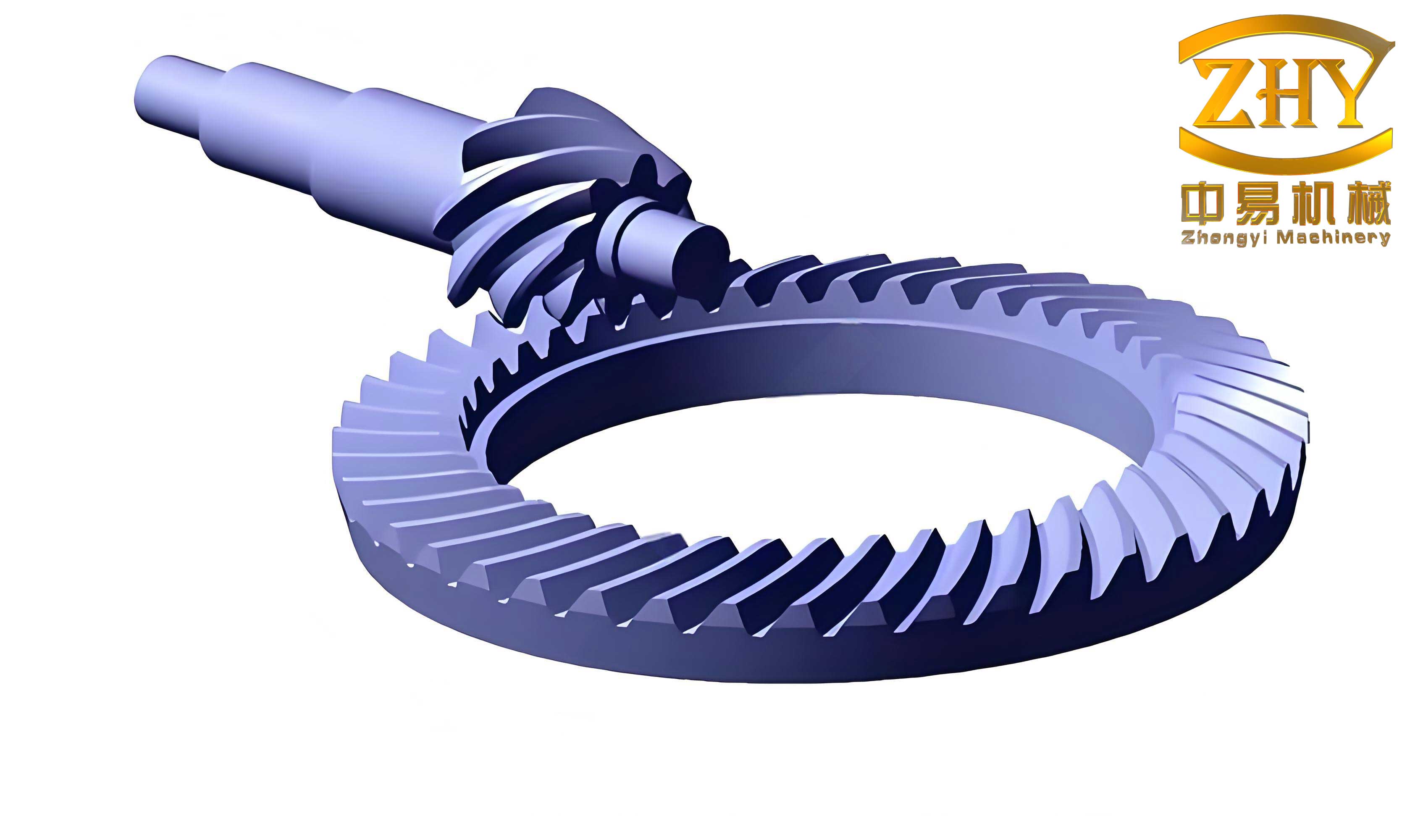
2. Surface Construction and Solid Modeling:
The computed point clouds for each tooth flank are exported as data files. These files are imported into UG NX (or any modern CAD software). In UG, the points are used to construct spline curves and then lofted or swept surfaces to form the tooth flank surfaces. For a single tooth, the convex flank surface, concave flank surface, fillet surfaces (modeled approximately), and the top land are created and stitched together to form a solid tooth. For the pinion, with only 4 teeth, the tooth geometry is particularly critical. The constructed pinion model allowed for direct visual inspection of the tooth form. The image below shows the resulting digital model of the 4-tooth pinion, confirming that with the chosen high spiral angle and profile shift, the tooth maintains a full, healthy profile without visible undercutting or excessive pointing. This successful digital validation is a key milestone in designing functional hyperbolic gears with very few teeth.
The gear model was constructed similarly. Once both gear and pinion were modeled, they could be assembled in the CAD environment with the correct offset and shaft angle. A basic kinematic simulation or contact analysis could be performed to check for interference and approximate contact patterns, though detailed loaded tooth contact analysis (LTCA) requires specialized software. The primary goal of this 3D simulation phase was geometric validation, and it conclusively demonstrated that the theoretical design for the 4:41 hyperbolic gear pair is geometrically feasible. The digital models serve as a direct input for downstream processes like CNC machining simulation or 3D printing for prototyping.
Experimental Validation: Gear Cutting and Physical Inspection
To move from digital simulation to physical reality, a cutting experiment was conducted to manufacture the designed 4:41 hyperbolic gear pair. The machining was performed on a Gleason GH-35 hypoid gear generator, a machine capable of both Formate cutting for the gear and generating (rolling) cutting for the pinion.
1. Gear (Wheel) Manufacturing:
The gear, with 41 teeth, was produced using the Formate method. This is a non-generated process where the gear blank is indexed intermittently, and a cutter head with inside and outside blades machines the tooth spaces in a fixed position relative to the blank. The machine settings—\( H_2 \), \( V_2 \), \( \gamma_m \) (root angle), \( X_{g2} \), and the cutter specifications—were calculated from the design data and input into the GH-35 machine. The Formate process is efficient and produces a precise gear whose tooth form is the conjugate envelope to the theoretical pinion. The tool point width \( W_2 \) was carefully controlled to ensure the correct pinion tip thickness.
2. Pinion Manufacturing:
The 4-tooth pinion was then cut using a generating (or rolling) method on the same machine. In this process, the pinion blank and a simulated crown gear (represented by the cutter head) are rolled together in a timed relationship according to the gear ratio. The cutter head used has a profile that matches the gear tooth form. Essentially, the machine simulates the meshing of the pinion with the already-designed gear, and the cutter carves out the pinion teeth as the envelope of that motion. This ensures the pinion tooth surface is the exact conjugate mate to the gear tooth surface. The machine settings for pinion generation, such as the ratio roll, sliding base, tilt, and swivel, were derived from the pinion design parameters.
3. Results and Inspection:
The cut gear and pinion were physically inspected. The tooth profiles were visually examined and measured using gear inspection equipment. The key findings were:
– The pinion exhibited four fully formed teeth without any signs of undercutting at the root or severe pointing at the tip.
– The tooth surfaces were smooth, and the flank geometry matched the design intent.
– The physical parts closely resembled the 3D digital models created earlier, confirming the accuracy of the mathematical model and simulation process.
The successful cutting of this pair demonstrates the practical feasibility of manufacturing hyperbolic gears with a pinion tooth count as low as four and a large speed ratio exceeding 10:1. This experimental validation is crucial, as it moves the concept from a theoretical or digital exercise into a tangible component that could be integrated into a transmission system.
Discussion: Implications and Future Directions for Hyperbolic Gears
The successful design, simulation, and manufacture of a 4:41 hyperbolic gear pair open new possibilities for compact high-ratio drives. The implications are significant for industries where space and weight are at a premium, such as aerospace, robotics, medical devices, and high-performance automotive applications. By enabling single-stage reductions that were previously only achievable with multi-stage gear trains or other mechanisms like worm gears (which have lower efficiency), these few-teeth hyperbolic gears offer a path to simpler, more efficient, and potentially quieter drives.
However, several challenges and research opportunities remain. The design process is highly iterative and sensitive to parameter choices. Future work could focus on developing automated optimization algorithms that simultaneously satisfy all geometric constraints (undercut, pointing, slot width, strength) while maximizing performance metrics like transmission error, contact pressure, or efficiency. Furthermore, the analysis performed here is primarily geometric. A comprehensive evaluation requires detailed Loaded Tooth Contact Analysis (LTCA) and stress analysis (bending and contact) to ensure durability under operating loads. The high spiral angle and few teeth may lead to high axial thrust loads, which must be accommodated by the bearing system. Thermal analysis is also important, as the high sliding velocities inherent in hyperbolic gear meshing can generate significant heat, especially in high-ratio designs.
Another avenue is the exploration of even more extreme ratios or fewer teeth. Could a 3:50 hyperbolic gear pair be designed and manufactured? The geometric constraints would become even more severe, potentially requiring non-standard cutter profiles or asymmetric tooth designs. Additive manufacturing (3D printing) of gears might facilitate the prototyping and production of such exotic geometries, allowing for topological optimization of the tooth shape and web structure for weight reduction.
The role of advanced materials and surface treatments is also critical. Case-hardened and ground hyperbolic gears are standard for high-performance applications. For few-teeth pinions, the root stress concentration is a concern, so material quality and precise heat treatment are paramount. Research into coatings to reduce friction and wear could enhance the performance and lifespan of these high-ratio hyperbolic gears.
In conclusion, this study has demonstrated a complete workflow for pushing the boundaries of hyperbolic gear design. From establishing and managing geometric constraints, through rigorous mathematical modeling and 3D simulation, to physical verification via cutting, we have shown that hyperbolic gears with very few teeth and large speed ratios are not only theoretically possible but also practically manufacturable. This expands the design space for engineers and provides a viable alternative for compact, high-torque reduction applications. As computational power and manufacturing techniques continue to advance, the potential for optimizing and deploying such innovative hyperbolic gear designs will only grow.