
As a professional deeply involved in the field of gear manufacturing, I have dedicated years to studying and refining the processing techniques for hypoid bevel gears. These gears, including spiral bevel gears and hypoid bevel gears, are critical components in transmitting motion between intersecting or skew axes, offering advantages such as high overlap ratios, robust load-bearing capacity, smooth operation, and reduced noise. They are indispensable in industries like automotive, aerospace, construction machinery, and machine tools. In this article, I will delve into the core processing technologies, emphasizing hypoid bevel gear methods, and provide detailed insights through principles, formulas, and comparative tables to enhance understanding and application.
The fundamental principle behind machining hypoid bevel gears involves simulating the meshing of a generated gear, such as a crown gear or a plane gear, with the workpiece. This is typically achieved on specialized gear milling machines where a cutter head, representing a tooth of an imaginary generating gear, interacts with the gear blank through controlled relative motions. The process mirrors the engagement of a pair of hypoid bevel gears, ensuring conjugate tooth surfaces. Over time, advancements have led to various machining strategies, each with unique characteristics and applications, which I will explore in depth.
Gear Cutting Processes: Principles and Methods
Hypoid bevel gear cutting primarily relies on the generating principle, where the cutter head’s rotation path mimics the tooth surface of a virtual crown gear. The machine’s cradle and the workpiece undergo relative rolling motions to complete the cutting of a tooth slot or flank. For spiral bevel gears with tapered teeth, the process is based on a virtual crown gear with a conical pitch surface, often using intermittent indexing. In contrast, for gears with constant-depth teeth, a plane crown gear principle is applied with continuous indexing. The basic generating motion can be described by the kinematic relationship between the workpiece and the cutter. For instance, the roll ratio $R$ is defined as the ratio of the angular velocity of the cradle to that of the workpiece, expressed as: $$ R = \frac{\omega_c}{\omega_w} $$ where $\omega_c$ is the cradle angular velocity and $\omega_w$ is the workpiece angular velocity. This parameter is crucial in determining the tooth geometry and contact pattern.
In addition to generating, other cutting methods have been developed for efficiency and precision. The form-cutting method is employed for driven gears with transmission ratios exceeding 2.5, where the tooth profile approximates a straight line. This non-generative approach uses a cutter whose blade shape directly imparts the tooth form, requiring corresponding modifications to the mating drive gear. Form-cutting can be implemented via standard milling cutter heads, circular broaching (pull-cutting), or spiral form-cutting—a specialized variant where the cutter head oscillates axially while rotating to produce tapered teeth. To correct the drive gear tooth surface in semi-generating processes, techniques like cutter tilt or modified roll are used. Cutter tilt involves inclining the cutter head axis to alter the generating gear pressure angle, while modified roll adjusts the instantaneous transmission ratio during cutting.
Further distinctions arise in continuous versus single-indexing methods. Face hobbing, or continuous indexing, involves synchronized rotation of the cutter and workpiece, similar to hobbing for cylindrical gears. It is highly efficient, often termed the “two-cut method,” but offers limited adjustability for contact patterns and surface finish, and is not suitable for grinding. Face milling, or single-indexing, uses a swinging workpiece motion without rotation, akin to milling. This “five-cut method” is common in mass production, allowing for grinding and better surface quality but requiring more machine setups and lower efficiency. The choice between these methods depends on production volume, gear specifications, and quality requirements, with hypoid bevel gears often benefiting from face milling due to their complex geometry.
| Method | Principle | Indexing Type | Efficiency | Contact Adjustability | Grindability | Typical Application |
|---|---|---|---|---|---|---|
| Face Hobbing | Continuous generating | Continuous | High | Low | No | High-volume, non-grindable gears |
| Face Milling | Single-index generating | Single | Moderate | High | Yes | Mass production, precision hypoid bevel gears |
| Form-Cutting | Non-generative | Single | Very High | Limited | Depends | Driven gears with high ratio |
The geometry of hypoid bevel gears involves complex parameters such as spiral angle, pressure angle, and offset distance. The tooth surface equation can be derived from the generating process. For a hypoid bevel gear, the position vector $\vec{r}$ of a point on the tooth surface relative to the gear coordinate system can be expressed as: $$ \vec{r}(u, \theta) = \mathbf{T}(\theta) \cdot \vec{r}_0(u) $$ where $u$ is a parameter along the tooth profile, $\theta$ is the rotation angle, $\mathbf{T}(\theta)$ is the transformation matrix accounting for the generating motion, and $\vec{r}_0(u)$ is the initial cutter profile. This equation underscores the mathematical intricacy in designing and manufacturing hypoid bevel gears.
Dry Cutting: Revolutionizing Hypoid Bevel Gear Production
Dry cutting has emerged as a transformative technology in hypoid bevel gear machining, eliminating the need for cooling lubricants and enhancing sustainability. In my experience, implementing dry cutting requires addressing several key factors. First, machine tools must feature high spindle speeds—modern CNC hypoid bevel gear milling machines can reach up to 2000 rpm, with cutting speeds approaching 300 m/min—along with efficient chip evacuation systems to manage heat generation. Second, cutting tools must exhibit exceptional properties: high hot hardness, thermal toughness, wear resistance, and anti-adhesion characteristics. This is achieved through advanced materials like carbide and specialized coatings. For instance, tools with PENTAC-style solid carbide inserts are designed explicitly for dry cutting of hypoid bevel gears. Third, process parameters must be optimized, including workpiece material hardness consistency and cutting conditions.
The advantages of dry cutting for hypoid bevel gears are substantial. Efficiency gains stem from reduced cycle times and elimination of coolant handling. Environmental benefits include minimized fluid waste and lower energy consumption. Cost reductions arise from savings on coolants, maintenance, and disposal. Moreover, dry cutting can improve gear accuracy by avoiding thermal distortions associated with coolants. The cutting force in dry conditions can be modeled using empirical formulas. For example, the tangential cutting force $F_t$ during hypoid bevel gear milling may be approximated as: $$ F_t = K_c \cdot a_p \cdot f_z \cdot z $$ where $K_c$ is the specific cutting force, $a_p$ is the depth of cut, $f_z$ is the feed per tooth, and $z$ is the number of teeth engaged. Dry cutting often allows higher $f_z$ values due to improved tool performance.
| Parameter | Typical Range | Influence on Process |
|---|---|---|
| Cutting Speed (v_c) | 200-300 m/min | Higher speeds reduce tool-workpiece contact time, managing heat |
| Feed per Tooth (f_z) | 0.1-0.3 mm/tooth | Affects surface finish and chip formation |
| Depth of Cut (a_p) | 0.5-2.0 mm | Determines material removal rate and tool load |
| Tool Coating | TiAlN, DLC | Enhances lubricity and thermal barrier for hypoid bevel gear cutting |
In practice, dry cutting of hypoid bevel gears necessitates rigorous monitoring of tool wear and workpiece temperature. I have observed that implementing infrared sensors or acoustic emission systems can help detect anomalies early. The transition to dry cutting aligns with industry trends toward greener manufacturing, making it a cornerstone for future hypoid bevel gear production.
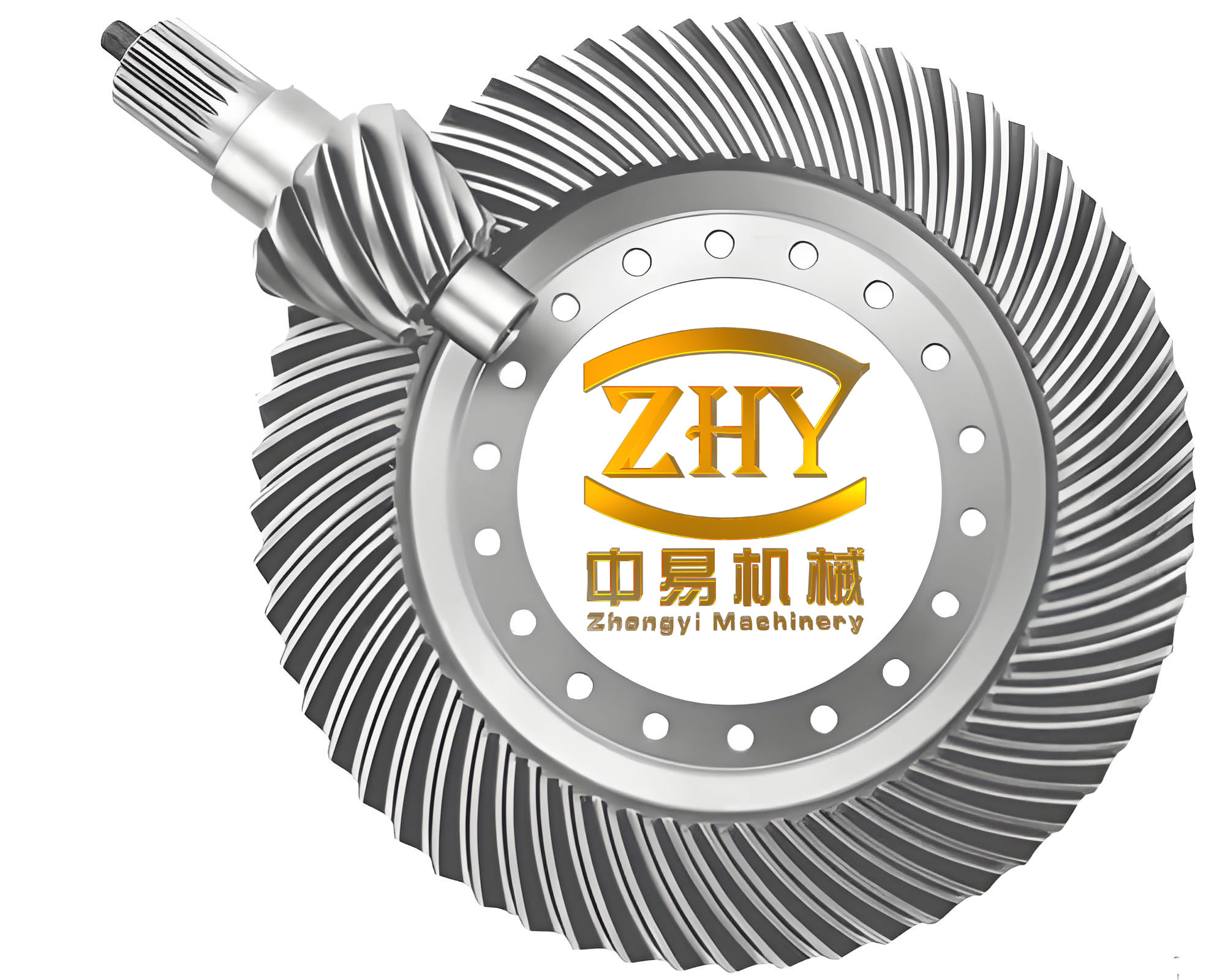
Gear Grinding: Achieving Precision in Hypoid Bevel Gears
Gear grinding is a critical finishing process for hypoid bevel gears, especially after heat treatment, to correct distortions and enhance accuracy. Traditional mechanical grinding machines relied on generating cam mechanisms to simulate the gear meshing motion, but they were limited to gears cut via generating methods and suffered from low efficiency. Modern CNC grinding machines have revolutionized this area by eliminating mechanical linkages and using direct computer control over axes. These machines offer flexibility, high precision, and the ability to grind hypoid bevel gears produced by various cutting methods, including those with cutter tilt modifications.
The grinding process for hypoid bevel gears involves using cup-shaped or threaded wheel grinding worms. The Universal Motion Concept (UMC) and Universal Motion Graph (UMG) technologies enable grinding paths that optimize tooth contact and noise reduction, potentially eliminating the need for subsequent lapping. The grinding depth $a_g$ is controlled to remove minimal material while achieving the desired profile. A common formula for material removal rate $Q_w$ in grinding is: $$ Q_w = a_g \cdot v_w \cdot b $$ where $v_w$ is the workpiece feed speed and $b$ is the grinding width. For hypoid bevel gears, $a_g$ is typically in the range of 0.01-0.05 mm per pass to avoid thermal damage.
Grinding hypoid bevel gears requires careful selection of grinding wheels—often vitrified bonded aluminum oxide or CBN wheels—and coolant strategies to manage heat. I have found that using oil-based coolants with high-pressure jets improves surface integrity. Additionally, post-grinding inspection via coordinate measuring machines (CMMs) or gear analyzers ensures compliance with tolerances. The gear quality parameters, such as tooth flank deviation $\Delta F_\alpha$ and pitch error $\Delta f_p$, can be expressed as: $$ \Delta F_\alpha = \max | f(x) – f_0(x) | $$ where $f(x)$ is the measured flank and $f_0(x)$ is the nominal flank. Grinding aims to minimize these deviations for hypoid bevel gears used in high-performance applications.
| Parameter | Value Range | Impact on Gear Quality |
|---|---|---|
| Grinding Wheel Speed | 30-60 m/s | Higher speeds reduce grinding forces but increase heat |
| Workpiece Feed Rate | 100-500 mm/min | Affects productivity and surface roughness |
| Coolant Flow Rate | 20-50 L/min | Critical for heat dissipation in hypoid bevel gear grinding |
| Dressing Interval | Every 5-20 gears | Maintains wheel sharpness and profile accuracy |
CNC Machining: Flexibility and Intelligence in Hypoid Bevel Gear Manufacturing
The advent of CNC technology has transformed hypoid bevel gear machining by replacing mechanical components like cradles and eccentrics with direct computer control. This eliminates errors from gears and linkages, enhancing precision and efficiency. CNC machines offer unparalleled flexibility—for instance, modern CNC gear cutters can handle both Gleason and Oerlikon tooth systems, a feat impossible with traditional machines. I have utilized such systems to implement closed-loop manufacturing, where data from gear measuring centers are fed back to adjust cutting parameters, quickly achieving ideal contact patterns for hypoid bevel gears.
CNC machining enables sophisticated motion control through programmed axes. The kinematic chain for a hypoid bevel gear CNC miller involves multiple linear and rotary axes, such as X, Y, Z for positioning, and A, B, C for tilting and rotation. The toolpath generation is based on digital models, allowing for rapid prototyping and customization. The relationship between axis movements and gear geometry can be described using transformation matrices. For example, the workpiece coordinate system $\{W\}$ is related to the machine coordinate system $\{M\}$ by: $$ \{W\} = \mathbf{Rot}_z(\phi) \cdot \mathbf{Trans}(x,y,z) \cdot \{M\} $$ where $\phi$ is the rotation angle and $\mathbf{Trans}$ accounts for offsets. This mathematical framework supports accurate machining of complex hypoid bevel gear designs.
Intelligent features in CNC systems include adaptive control, where cutting forces are monitored in real-time to adjust feeds and speeds, optimizing tool life and surface finish for hypoid bevel gears. Additionally, simulation software predicts chip formation and thermal effects, reducing trial runs. The integration of IoT and data analytics further enables predictive maintenance and quality assurance. In my work, I have seen CNC machines achieve tooth flank accuracies of IT5-IT6 grades for hypoid bevel gears, crucial for automotive differentials.
| Axis | Motion Type | Role in Gear Cutting |
|---|---|---|
| X-axis | Linear | Radial positioning of cutter relative to hypoid bevel gear blank |
| Y-axis | Linear | Tangential adjustment for offset in hypoid bevel gears |
| Z-axis | Linear | Axial depth control |
| A-axis | Rotary | Cradle simulation or workpiece tilt |
| B-axis | Rotary | Cutter head swivel for pressure angle changes |
| C-axis | Rotary | Workpiece rotation for indexing |
Alternative Machining: Non-Dedicated Machine Tools for Hypoid Bevel Gears
Beyond dedicated gear machines, hypoid bevel gears can be produced on universal five-axis machining centers with CAM software support. This approach is advantageous for large-module, hard-faced, wide-face, and high-precision hypoid bevel gears, complementing traditional methods. The process involves using end mills or ball-nose tools to sculpt the tooth flanks based on CAD models. The tool orientation is critical to avoid gouging and ensure accuracy. The scallop height $h_s$, which affects surface finish, can be estimated as: $$ h_s = R – \sqrt{R^2 – \left(\frac{s}{2}\right)^2} $$ where $R$ is the tool radius and $s$ is the stepover distance. For hypoid bevel gears, $s$ is kept small (e.g., 0.1-0.5 mm) to achieve smooth profiles.
This method offers flexibility for low-volume or prototype production of hypoid bevel gears. However, it requires advanced post-processing and simulation to generate collision-free toolpaths. I have employed this technique for custom hypoid bevel gears in aerospace applications, where design iterations are frequent. The material removal rate is lower than dedicated cutting, but the ability to machine complex geometries without specialized tooling is a significant benefit.
Future Directions and Conclusion
The evolution of hypoid bevel gear processing is steering toward dry cutting, grinding, and CNC integration. Dry cutting reduces environmental impact and costs, while grinding ensures high precision for hardened gears. CNC technology provides the intelligence and flexibility needed for modern manufacturing. Emerging trends include additive manufacturing for gear prototypes, AI-driven process optimization, and digital twins for virtual validation. In all these areas, the focus remains on enhancing the performance and reliability of hypoid bevel gears.
In summary, hypoid bevel gear manufacturing encompasses a spectrum of technologies, from traditional generating to advanced dry cutting and CNC grinding. Each method has its place, influenced by factors like production volume, gear specifications, and quality demands. As an engineer, I believe that continuous innovation in tool materials, machine design, and process control will further elevate the capabilities of hypoid bevel gears, ensuring their pivotal role in mechanical transmissions for years to come. The mathematical and technical depth involved underscores the sophistication required to produce these essential components efficiently and accurately.