
Traditional finite element analysis of hyperbolic gear meshing often isolates the gear pair from its surrounding assembly. In such analyses, boundary conditions and loads are applied directly to the gears—typically by fixing the crown gear and applying a pure torque to the pinion shaft. This approach introduces significant simplifications that diverge from real-world operating conditions. The actual boundary conditions for the gears are governed by the compliance of the housing, the stiffness of supporting bearings, and the dynamic interaction with other driveline components like the differential and axles. Furthermore, applying a concentrated torque does not accurately replicate the distributed nature of load transfer across the potentially multiple gear teeth in contact. To overcome these limitations, this article develops and validates a complete drive axle finite element model. This integrated approach allows for the simulation of hyperbolic gear meshing under realistic system-level constraints and loading, leading to more accurate predictions of contact and bending stresses essential for durability assessment and design optimization.
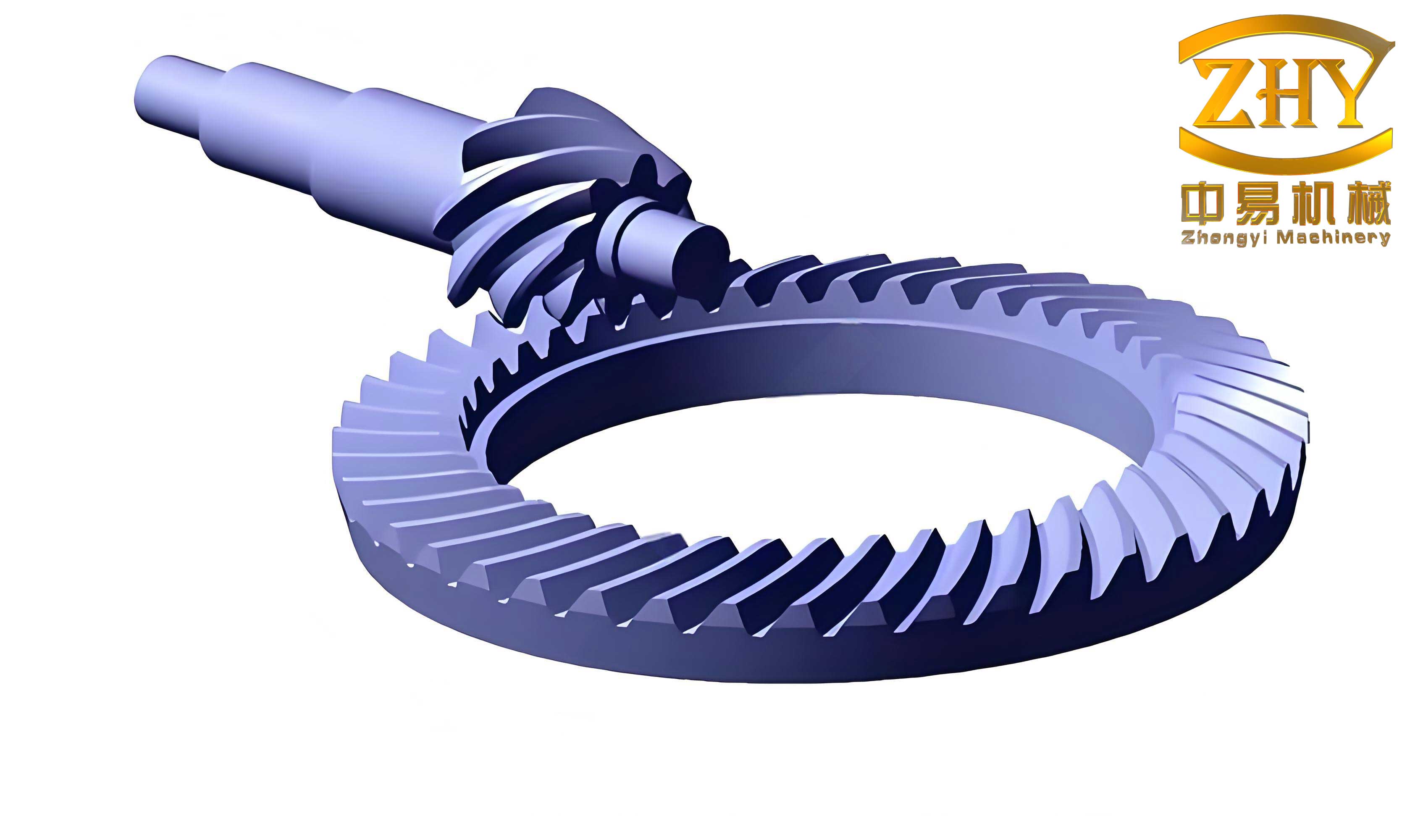
The core of the drive axle model includes all major structural and drivetrain components: the axle housing, the differential carrier, the pinion and crown hyperbolic gears, the differential case, the sun gears and side gears, the axle shafts, and the wheel hubs. Creating an accurate geometric model of the hyperbolic gear teeth is critical. Instead of relying solely on theoretical gear geometry, a reverse engineering approach was employed. Physical gears were scanned to capture the precise topography of the active tooth flanks, ensuring the digital model accurately reflects manufactured surfaces, including any inherent micro-geometrical modifications. This high-fidelity gear geometry is then integrated into the full assembly. The meshing process utilizes a combination of element types: predominantly hexahedral elements for volumetric accuracy in critical parts like the gears, and tetrahedral elements for complex geometries. Contact interactions between the hyperbolic gear flanks are defined using a surface-to-surface contact algorithm with a penalty friction formulation. Key connections, such as bearings (simplified as coupling constraints at journal centers) and splines, are modeled to represent the load paths accurately. The complete finite element model of the drive axle assembly is shown conceptually below, highlighting the integrated nature of the analysis.
Before proceeding to the nonlinear hyperbolic gear contact analysis, the global finite element model must be validated to ensure it correctly represents the dynamic stiffness and mass distribution of the physical axle. A modal validation was performed. The experimental setup involved suspending the drive axle with soft springs to approximate free-free boundary conditions. An electromagnetic shaker provided excitation, and response was measured to extract natural frequencies and mode shapes. The same conditions were simulated in the FE model using a Lanczos eigensolver. The correlation between test and simulation for the first four global bending modes is presented in Table 1. The close agreement, with errors under 6%, confirms that the model’s stiffness and mass properties are representative of the physical assembly. The slightly higher computed frequencies are attributed to the simplifying assumption of tied connections in some interfaces, which increases overall model stiffness.
| Mode Description | FE Model Frequency (Hz) | Test Frequency (Hz) | Error (%) |
|---|---|---|---|
| 1st Bending (Fore-Aft) | 80.4 | 76.9 | 4.35 |
| 1st Bending (Vertical) | 81.9 | 79.8 | 2.56 |
| 2nd Bending (Fore-Aft) | 262.8 | 254.2 | 3.27 |
| 2nd Bending (Vertical) | 285.2 | 268.8 | 5.75 |
For the quasi-static meshing analysis, a representative high-speed cruise condition was simulated. An angular velocity of 322 rad/s was applied to the pinion input shaft, corresponding to a vehicle speed of 100 km/h. A resistive torque of 656 N·m was applied to each wheel hub, representing the road load. The analysis was performed using an explicit dynamics solver (Abaqus/Explicit) run in quasi-static mode, simulating one full revolution of the crown hyperbolic gear. This method efficiently handles the complex, nonlinear contact conditions between the hyperbolic gear teeth. The primary outputs are the time-history of contact pressure on the tooth flanks and bending stresses at the tooth roots for both the pinion and crown hyperbolic gears.
To validate the stress predictions from the system model, a physical bench test was conducted to measure tooth-root bending strain. Strain gauges were mounted at strategic locations on the root fillet of a crown hyperbolic gear tooth: at the entry, middle, and exit regions of the potential contact zone. Tests were run under identical speed and load conditions as the simulation. The measured strain was converted to stress using Hooke’s Law ($\sigma = E \cdot \epsilon$). Figure 1 compares the simulated and measured bending stress history at these three points for one meshing cycle. The correlation in both magnitude and trend is excellent, with a maximum error of 16% at the most critical point. This agreement provides high confidence in the model’s ability to predict localized stress states within the hyperbolic gear pair.
The meshing analysis reveals the complex, multi-tooth contact pattern characteristic of hyperbolic gears. At the given load, up to three tooth pairs are in contact simultaneously. The contact imprint on the tooth flank is not a perfect ellipse but an irregular patch, influenced by system deflections. The contact path follows the typical motion from the toe (inner end) to the heel (outer end) on the crown gear, ensuring smooth torque transfer. The fundamental relationship governing the nominal contact pressure in gear teeth is given by the Hertzian contact theory. For two curved surfaces in contact, the maximum contact pressure $p_0$ can be expressed as:
$$ p_0 = \sqrt[3]{\frac{6 P E_{eq}^2}{\pi^3 R_{eq}^2}} $$
where $P$ is the normal load per unit face width, $E_{eq}$ is the equivalent modulus of elasticity, and $R_{eq}$ is the equivalent radius of curvature at the point of contact. However, in a loaded hyperbolic gear pair within a compliant system, the actual load distribution $P$ along the line of action and the effective radii of curvature are dynamically influenced by neighboring tooth contacts and global deformations, which this system model captures.
The stress state within the hyperbolic gear teeth is biaxial. The contact region is under triaxial compression, while the surrounding material, particularly on the tensile side of the tooth root, experiences significant principal stress. The bending stress at the root is the primary driver for tooth breakage failure. According to the Lewis bending formula, the nominal bending stress $\sigma_b$ is proportional to the tangential load $F_t$ and inversely proportional to the face width $b$ and module $m$:
$$ \sigma_b \propto \frac{F_t}{b m Y} $$
where $Y$ is the Lewis form factor. In a hyperbolic gear pair, the load sharing among multiple teeth and the stress concentration at the root fillet make the actual stress far more complex than this simple formula suggests. Analyzing the stress history for a single tooth pair through its engagement provides critical insights. The equivalent (von Mises) stress on the tensile and compressive sides of the tooth root for both pinion and crown hyperbolic gears was extracted and is summarized in Table 2, highlighting key observations.
| Gear | Stress Side | Magnitude Trend | Critical Phase | Root Cause |
|---|---|---|---|---|
| Crown Gear | Tensile | Highest Overall | Entry & Exit | Edge Contact, Highest Load Share |
| Compressive | High | Entry & Exit | Reaction to Tensile Stress | |
| Pinion Gear | Tensile | Moderate | Mid-engagement | Full Contact Load |
| Compressive | Lower | Mid-engagement | Reaction to Tensile Stress |
The data shows that the crown hyperbolic gear consistently experiences higher root bending stresses than the pinion. This is primarily due to its larger diameter and lower rotational speed, resulting in it being the torque-receiving member. A significant finding is the “edge contact” phenomenon. As a tooth on the crown hyperbolic gear begins to mesh (entry) or is about to leave mesh (exit), contact can occur near the edge of the tooth flank. This misaligned contact creates a larger bending moment arm, leading to a pronounced peak in tensile stress at the corresponding root. This stress peak often defines the maximum bending stress in the design cycle. The compressive-side stress follows a similar trend but at a lower magnitude, as most metallic gear materials have higher compressive yield strength.
While bending stress is critical for tooth integrity, contact stress governs surface durability, such as pitting and spalling. The contact pressure history for nodes along the path of contact was analyzed. The contact stress on the pinion tooth flank is notably higher than on the crown gear flank. This can be attributed to the pinion’s smaller radius of curvature, which, according to Hertzian theory, leads to higher pressure for the same load. Furthermore, the pinion’s higher rotational speed may induce greater dynamic effects. The maximum contact pressure for both gears occurs not during edge contact, but at the point of fullest, most centered contact during mid-engagement, where the load per tooth is at its peak for that particular pair. The trends for contact pressure are contrasted in Table 3.
| Parameter | Pinion Gear | Crown Gear | Governing Factor |
|---|---|---|---|
| Relative Magnitude | Higher | Lower | Smaller Radius of Curvature |
| Peak Occurrence | Mid-engagement | Mid-engagement | Maximum Load Share for the Pair |
| Sensitivity to Edge Contact | Lower | Higher | Flank Geometry & Toe/Heel Relief |
The complete system modeling approach fundamentally changes how boundary conditions are applied for hyperbolic gear analysis. Instead of arbitrary constraints, the gears find their own equilibrium position within the deflecting system. The input torque and speed are applied at the physically correct locations—the input pinion shaft and the wheel hubs. The resulting load distribution on the hyperbolic gear teeth is an outcome of solving the complete static equilibrium of the entire constrained system, including bearing clearances and housing flexibility. This represents a significant advancement over traditional decoupled analysis. The governing equations for the system in quasi-static equilibrium can be conceptually framed as solving for the displacement vector $\mathbf{u}$ that satisfies:
$$ \mathbf{K}(\mathbf{u}) \mathbf{u} = \mathbf{F} $$
where $\mathbf{K}(\mathbf{u})$ is the stiffness matrix, which is nonlinear due to changing contact conditions in the hyperbolic gear pair and other joints, and $\mathbf{F}$ is the vector of applied forces and torques at the boundaries. The explicit dynamics solver used marches through time to find this equilibrium state iteratively under the applied rotational motion.
In conclusion, the analysis based on a complete drive axle model provides a far more realistic simulation of hyperbolic gear meshing compared to traditional isolated gear pair analysis. The model was rigorously validated through global modal tests and local strain measurements, ensuring fidelity. The key findings from the quasi-static stress analysis are that the crown hyperbolic gear is more critical for bending fatigue due to higher root stresses exacerbated by edge contact during entry and exit. Conversely, the pinion hyperbolic gear is more critical for contact fatigue due to higher surface contact pressures, which peak during full engagement. These insights, derived from a system-level perspective, are crucial for targeted design improvements. For instance, crown gear design could focus on optimizing tip and root relief to mitigate edge contact stresses, while pinion design could benefit from optimized surface treatments or curvature to manage contact pressure. This integrated modeling methodology establishes a robust framework for the virtual design and durability assessment of hyperbolic gear systems in automotive drivelines.