
In the realm of gear transmission design, the classical theory of spatial meshing serves as the foundational framework. This body of work systematically details the fundamental principles governing conjugate surfaces and gear geometry. Modern advancements, such as tooth flank topological modification and ease-off surface simulation, are all built upon this bedrock of conjugate surface theory. More recently, the principle of conjugate curves for gear transmission has been proposed, offering novel methodologies for flank construction. Within this rich theoretical landscape, the work of synthesizing the core concepts of classical gear meshing theory into two distinct categories of eigenfunctions stands out for its clarity. Building upon this synthesis, the present analysis utilizes differential methods for conjugate surfaces to explicitly define these two categories of eigenfunctions and their associated vectors. This formalization extends the expressive power for parameters critical to surface contact and lubrication performance. The spatially complex hyperbolic gear serves as an exemplary case study. Its meshing characteristics are analyzed through the lens of these eigenfunctions, with a particular focus on elucidating the influence mechanism of the cutter head radius. The definitions and expressions provided herein aim to clarify the core logic of conjugate surface theory, facilitating its correct understanding and application, and thereby laying a solid foundation for the design and control of gear meshing performance.
The analysis begins with the fundamental equation of meshing for conjugate surfaces \(\Sigma^{(1)}\) and \(\Sigma^{(2)}\): \( \mathbf{n} \cdot \mathbf{v}^{(12)} = 0 \). Differentiating this equation and performing transformations leads to the following relation:
$$ \mathbf{n} \cdot \left[ \boldsymbol{\omega}^{(12)} \times (\boldsymbol{\omega}_1 \times \mathbf{r}_1) – \boldsymbol{\omega}_1 \times \mathbf{v}^{(12)} \right] = – \frac{d_1\mathbf{r}_1}{dt} \cdot \left[ \mathbf{n} \times \boldsymbol{\omega}^{(12)} + \mathbf{v}^{(12)} \frac{d_1\mathbf{n}}{ds} \right] $$
By defining two key vectors:
$$ \mathbf{q} = \boldsymbol{\omega}^{(12)} \times (\boldsymbol{\omega}_1 \times \mathbf{r}_1) – \boldsymbol{\omega}_1 \times \mathbf{v}^{(12)} $$
$$ \mathbf{p} = (\boldsymbol{\omega}^{(12)} \times \mathbf{n}) – \mathbf{v}^{(12)} \frac{d_1\mathbf{n}}{ds} $$
we arrive at the definitions for the two eigenfunctions:
$$ \Phi_I(u, v, t) = \frac{d_1\mathbf{r}_1}{dt} \cdot \mathbf{p} = \mathbf{n} \cdot \mathbf{q} $$
$$ \Phi_{II}(u, v, t) = \frac{d_2\mathbf{r}_2}{dt} \cdot \mathbf{p} = \mathbf{n} \cdot \mathbf{q} + \mathbf{p} \cdot \mathbf{v}^{(12)} $$
Here, \(\Phi_I\) and \(\Phi_{II}\) are termed the first-order and second-order characteristic functions of the conjugate surfaces, respectively, while \(\mathbf{q}\) and \(\mathbf{p}\) are their corresponding characteristic vectors. These functions encapsulate the first and second-order differential properties of the meshing surfaces.
The first-order characteristic vector \(\mathbf{q}\) can be geometrically interpreted. It represents a screw motion of the contact point about the center distance vector \(\mathbf{a}\), combining rotation and translation. The function \(\Phi_I\) is the projection of \(\mathbf{q}\) onto the surface normal \(\mathbf{n}\). The condition \(\Phi_I = 0\) defines the limit (or first-order boundary) on surface \(\Sigma^{(1)}\). At this boundary, the velocity of the contact point along \(\Sigma^{(1)}\) is zero, while on \(\Sigma^{(2)}\) it equals the relative sliding velocity \(\mathbf{v}^{(12)}\). This boundary separates the working zone from the non-contact zone on \(\Sigma^{(1)}\).
The second-order characteristic function and vector are intimately linked to surface curvature. The vector \(\mathbf{p}\) lies in the tangent plane and is perpendicular to the instantaneous contact line. The condition \(\Phi_{II} = 0\) defines the curvature interference (or second-order) boundary on surface \(\Sigma^{(2)}\), beyond which undercutting occurs. Crucially, the induced normal curvature (principal value) at the contact point is given by:
$$ K_{II} = \frac{\|\mathbf{p}\|^2}{\Phi_{II}} $$
Furthermore, key kinematic and tribological parameters for the meshing interface can be elegantly expressed using these eigenfunctions. The entrainment velocity \(u_e\), vital for elastohydrodynamic lubrication (EHL), and the sliding velocity \(u_s\) are:
$$ u_e = -\frac{\Phi_I + \Phi_{II}}{2 \|\mathbf{p}\|}, \quad u_s = \frac{\Phi_{II} – \Phi_I}{\|\mathbf{p}\|} $$
The slide-to-roll ratio \(s_r\), another critical EHL parameter, is their ratio: \(s_r = u_s / u_e\). The sliding ratios for the two surfaces are:
$$ \sigma_1 = 1 – \frac{\Phi_{II}}{\Phi_I}, \quad \sigma_2 = 1 – \frac{\Phi_I}{\Phi_{II}} $$
The comprehensive (or equivalent) radius of curvature, which directly influences contact stress, is the inverse of the induced curvature:
$$ r_{II} = \frac{1}{K_{II}} = \frac{\Phi_{II}}{\|\mathbf{p}\|^2} $$
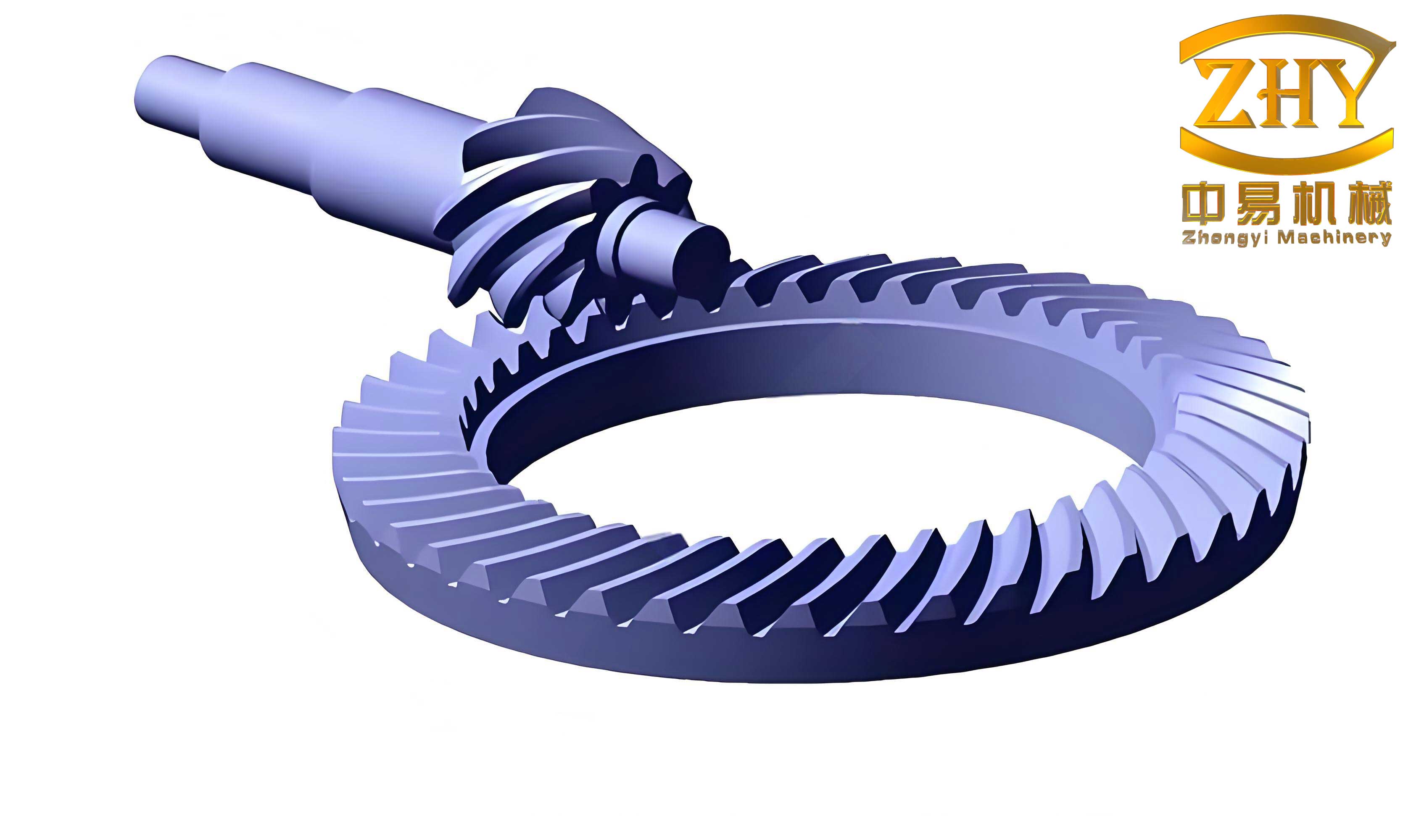
The hyperbolic gear is an ideal subject for applying this framework due to its complex spatial geometry and motion. The geometric design of a hyperbolic gear set is significantly influenced by the cutter head radius \(r_0\). According to classical design algorithms, the first-order characteristic function \(\Phi_I = 0\) is used to determine limiting parameters, ensuring the active tooth surface avoids the meshing boundary and lubrication dead points (where the entrainment angle becomes zero). The choice of \(r_0\) therefore plays a pivotal role in controlling meshing performance. To investigate this, a hyperbolic gear pair with a ratio of 6:39, 35mm offset, and a pinion spiral angle of 50° was analyzed using three different cutter head sizes. The resulting major geometric parameters are summarized in the table below.
| Parameter | 6″ Cutter (r0=76.2 mm) | 7.5″ Cutter (r0=95.25 mm) | 9″ Cutter (r0=114.3 mm) |
|---|---|---|---|
| Pinion Face Width (mm) | 47.365 | 47.403 | 47.423 |
| Pressure Angle, Drive/Coast (°) | 15.940 / -22.060 | 14.841 / -23.159 | 14.106 / -23.894 |
| Pinion Pitch Angle (°) | 12.493 | 10.441 | 9.075 |
| Gear Spiral Angle (°) | 29.001 | 28.987 | 28.962 |
| Gear Pitch Angle (°) | 76.534° | 78.714° | 80.169° |
The mathematical model for the gear flank is derived from the cutter surface. In a coordinate system attached to the pitch plane, the cutter surface vector \(\mathbf{r}_c\) and unit normal \(\mathbf{n}_c\) for generating the gear are:
$$ \mathbf{r}_c = \begin{bmatrix} r_u \cos \theta \\ r_u \sin \theta \\ u \cos \alpha \end{bmatrix}, \quad \mathbf{n}_c = \begin{bmatrix} -\cos \alpha \cos \theta \\ \cos \alpha \sin \theta \\ \sin \alpha \end{bmatrix} $$
where \(r_u = r_0 – u \sin \alpha\). Through a series of coordinate transformations involving the machine settings (root angle \(\theta_f\), pitch angle \(\delta_2\), spiral angle \(\beta_2\)) and the rotational motion of the gear blank (\(\varphi\)), the final flank surface \(\mathbf{r}_m^{(2)}\) and its normal \(\mathbf{n}_m^{(2)}\) in the fixed frame are obtained. The meshing equation \(f(\theta, u, \varphi) = \mathbf{n}_m^{(2)} \cdot \mathbf{v}^{(21)} = 0\) is then solved to establish the functional relationship between the surface parameters and the gear rotation angle, defining the path of contact.
The analysis of meshing characteristics proceeds by calculating the two characteristic functions and vectors for points across the tooth surface. For the baseline case using the 7.5″ cutter, key parameters are computed. The results indicate that the hyperbolic gear tooth surface operates away from meshing boundaries and lubrication dead points. The sliding velocity \(u_s\) and the slide-to-roll ratio \(s_r\) show relatively uniform distributions across the flank. The presence of a significant angle between the contact line and the relative velocity vector \(\mathbf{v}^{(21)}\) provides a substantial entrainment velocity \(u_e\), conducive to forming a lubricant film. The comprehensive radius of curvature \(r_{II}\) also varies smoothly, influencing the contact patch size and stress.
The core investigation involves comparing the influence of the cutter head radius \(r_0\) on the derived meshing performance parameters. The following formulas are central to this comparison, derived from the eigenfunctions:
$$ u_e(r_0) = -\frac{\Phi_I(r_0) + \Phi_{II}(r_0)}{2 \|\mathbf{p}(r_0)\|}, \quad s_r(r_0) = \frac{\Phi_{II}(r_0) – \Phi_I(r_0)}{\Phi_{II}(r_0) + \Phi_I(r_0)}, \quad r_{II}(r_0) = \frac{\Phi_{II}(r_0)}{\|\mathbf{p}(r_0)\|^2} $$
The computational results for the three cutter sizes are summarized qualitatively in the table below, highlighting trends.
| Performance Metric | Trend with Decreasing Cutter Radius (r0) | Implication for Hyperbolic Gear Performance |
|---|---|---|
| Entrainment Velocity (ue) | Increases | Improves lubricant film formation and thickness. |
| Slide-to-Roll Ratio (sr) | Decreases (more favorable distribution) | Reduces sliding friction losses and shear heating in the EHL contact. |
| Comprehensive Radius (rII) | Significantly Increases | Lowers contact pressure (Hertzian stress) for a given load, improving contact fatigue life. |
The analysis clearly demonstrates that a smaller cutter head radius is beneficial from a pure contact mechanics and tribological perspective for hyperbolic gear pairs. It generates a larger comprehensive radius of curvature, reducing contact stress. Simultaneously, it promotes higher entrainment velocity and a lower slide-to-roll ratio, both of which are favorable conditions for effective elastohydrodynamic lubrication. This synergy suggests a potential for improved surface durability and efficiency. However, this advantage must be balanced against manufacturing considerations, as a larger cutter head can accommodate more blade groups, potentially increasing cutting efficiency and stability during production.
In conclusion, the framework of two characteristic functions provides a powerful and unified method for analyzing conjugate surface meshing. By defining the first and second-order eigenfunctions \(\Phi_I\), \(\Phi_{II}\) and their vectors \(\mathbf{q}\), \(\mathbf{p}\), the core aspects of gear meshing—including boundary identification, induced curvature, and key kinematic parameters for lubrication—are expressed in a coherent mathematical language. Applying this framework to the hyperbolic gear reveals the profound influence of the generating cutter head radius on meshing performance. The finding that a smaller radius enhances both contact and lubrication characteristics offers valuable guidance for the topological design and performance optimization of hyperbolic gear surfaces, enabling a more informed trade-off between theoretical performance limits and practical manufacturing constraints.