
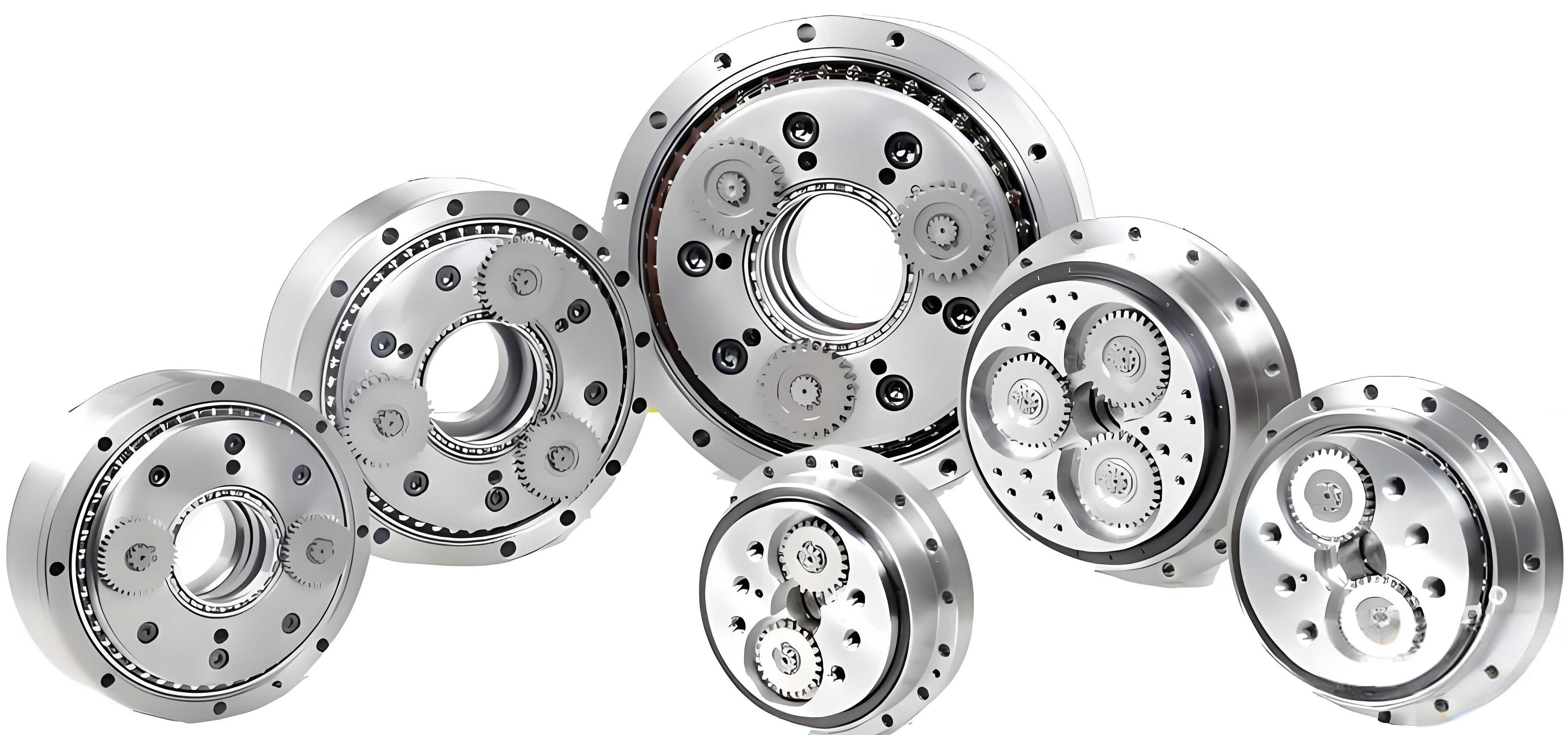
In the field of industrial robotics, precision reducers play a critical role in ensuring high performance and accuracy. Among these, the rotary vector reducer, commonly known as the RV reducer, is a key component due to its compact design, high torque capacity, and excellent backlash characteristics. Traditional rotary vector reducers typically combine a first-stage involute planetary gear mechanism with a second-stage cycloidal pin-wheel mechanism. However, in this study, I propose an innovative design that replaces the second-stage external cycloidal transmission with an internal cycloidal planetary transmission. This new rotary vector reducer offers advantages such as a more compact axial profile, easier hollow structural implementation, and improved dynamic performance. The primary goal of this research is to investigate the transmission characteristics of this novel rotary vector reducer through comprehensive modeling, simulation, and analysis.
The motivation behind this work stems from the growing demand for advanced reducers in applications like robotics, CNC machine tools, and aerospace systems. Conventional rotary vector reducers, while effective, can be limited in terms of miniaturization and customization. By leveraging internal cycloidal principles, the new design aims to address these limitations. Throughout this article, I will detail the theoretical foundations, design process, virtual prototyping, and dynamic analysis of the novel rotary vector reducer. The keyword “rotary vector reducer” will be emphasized repeatedly to highlight the focus of this study.
To begin, let’s explore the fundamental principles of internal cycloidal transmission. Internal cycloidal planetary transmission is a type of few-teeth-difference planetary gear transmission. In this mechanism, the external gear is typically a pin-wheel, while the internal gear’s tooth profile is derived from the equidistant curve of a shortened internal cycloid. The generation of the shortened internal cycloid is based on the rolling of a circle inside a base circle. Specifically, consider a rolling circle with radius $r$ and center $O$ that rolls without slipping inside a base circle with radius $R_z$ and center $O_a$. A point $M$ on the rolling circle traces a shortened internal cycloid. The centers of the pins are uniformly distributed on a pin distribution circle with radius $R$ and center $O_b$, corresponding to points $M_1, M_2, \ldots$ on the cycloid. The tooth profile of the cycloidal gear is the outer equidistant curve of this shortened internal cycloid, with an equidistant distance equal to the pin radius $r_z$. The number of pins $z_b$ is one less than the number of cycloidal gear teeth $z_a$.
The parametric equations for the theoretical tooth profile curve of the internal cycloidal gear are given by:
$$x_0 = \frac{z_b}{K_1} A \cos \psi + A \cos \left( \frac{z_b}{K_1} \psi \right)$$
$$y_0 = \frac{z_b}{K_1} A \sin \psi + A \sin \left( \frac{z_b}{K_1} \psi \right)$$
Here, $(x_0, y_0)$ represents the coordinates of the theoretical tooth profile curve, $K_1$ is the shortening coefficient of the theoretical tooth profile, defined as $K_1 = OM / r$, $A$ is the eccentric distance (i.e., $A = O_a O_b$), and $\psi$ is the angle through which the rolling circle center $O$ rotates around the base circle center $O_a$. Given the pin radius $r_z$, the parametric equations for the actual tooth profile curve become:
$$x = \cos \psi \left( \frac{A z_b}{K_1} + \frac{r_z}{\sqrt{W_1′}} \right) + \cos \left( \frac{z_b}{K_1} \psi \right) \left( A – \frac{K_1 r_z}{\sqrt{W_1′}} \right)$$
$$y = \sin \psi \left( \frac{A z_b}{K_1} + \frac{r_z}{\sqrt{W_1′}} \right) – \sin \left( \frac{z_b}{K_1} \psi \right) \left( A – \frac{K_1 r_z}{\sqrt{W_1′}} \right)$$
where $W_1′ = 1 + K_1^2 – 2K_1 \cos((z_b + 1)\psi)$. These equations form the mathematical basis for designing the internal cycloidal gear in the novel rotary vector reducer. Understanding these principles is crucial for optimizing the gear geometry and ensuring efficient power transmission.
Building on this theoretical foundation, I designed the novel rotary vector reducer with an internal cycloidal transmission stage. The overall structure integrates a first-stage involute planetary gear set with the second-stage internal cycloidal mechanism. This combination aims to achieve high reduction ratios while maintaining compactness. Key design parameters were carefully selected to balance performance factors such as torque capacity, efficiency, and size. The table below summarizes the main technical parameters used in the design of this rotary vector reducer.
| Parameter | Value |
|---|---|
| Pin distribution circle diameter (mm) | 50 |
| Pin diameter (mm) | 4 |
| Eccentric distance (mm) | 1 |
| Number of cycloidal gear teeth | 41 |
| Sun gear output teeth | 63 |
| Planet gear teeth | 17 |
| Sun gear input teeth | 102 |
| Module (mm) | 2 |
| Involute gear pressure angle (degrees) | 20 |
| Motor input speed (rpm) | 1500 |
| Motor output gear teeth | 34 |
Using 3D modeling software, I created detailed models of all critical components, including the internal cycloidal gear, crank shaft, sun gear, planet gears, and output plate. Standard parts like bearings and washers were also incorporated. The assembly process involved thorough interference checks, both static and dynamic, to ensure proper fit and function. For simulation purposes, the model was simplified by removing non-essential components like seals, which do not significantly impact dynamic analysis. The final 3D assembly of the novel rotary vector reducer showcases its compact and integrated design, which is a hallmark of advanced rotary vector reducer technology.
To evaluate the dynamic behavior of this rotary vector reducer, I employed virtual prototyping techniques within a multi-body dynamics environment. The software ADAMS was used to construct a dynamic model and perform simulations under realistic operating conditions. The input was set to a motor speed of 1500 rpm, corresponding to a sun gear speed of 500 rpm (or 3000 °/s) after accounting for the gear ratio of the motor output gear (34 teeth) and sun gear input (102 teeth). The overall reduction ratio of the rotary vector reducer was designed to be 32, leading to an expected output plate speed of approximately 278 °/s. A rated load torque of 681 N·m was applied to the output plate to simulate typical working conditions.
In ADAMS, constraints were applied to replicate real-world interactions. These included fixed joints, revolute joints, and gear pairs. Contact forces between the cycloidal gear and pins were modeled using the IMPACT function, which calculates forces based on penetration depth and stiffness. The table below lists the constraints applied in the virtual prototype of the rotary vector reducer.
| Constraint Type | Component 1 | Component 2 | Quantity |
|---|---|---|---|
| Fixed Joint | Crank Shaft Cage | Ground | 1 |
| Fixed Joint | Crank Shaft Cage | Output Plate Cage | 1 |
| Fixed Joint | Planet Gear | Crank Shaft | 2 |
| Revolute Joint | Sun Gear | Crank Shaft Cage | 1 |
| Revolute Joint | Planet Gear | Crank Shaft Cage | 2 |
| Revolute Joint | Output Plate | Crank Shaft Cage | 1 |
| Revolute Joint | Crank Shaft | Cycloidal Gear | 4 |
| Revolute Joint | Pin | Output Plate | 40 |
| Gear Pair | Sun Gear | Planet Gear | 2 |
The simulation was run for 3 seconds with 500 steps. Key results focused on the speed and angular velocity of major components, as well as contact forces between the cycloidal gear and pins. The angular velocity curves for the sun gear and output plate confirmed the expected reduction ratio. The sun gear rotated at a constant 3000 °/s, while the output plate averaged 278 °/s, aligning with the design specifications of the rotary vector reducer. This consistency validates the fundamental kinematics of the novel design.
Furthermore, the centroid velocity of the cycloidal gear was analyzed in the X and Y directions. The curves exhibited sinusoidal and cosinusoidal patterns, respectively, indicating that the cycloidal gear undergoes a circular motion relative to the reducer center. This motion is characteristic of cycloidal drives and is essential for torque transmission in a rotary vector reducer. The equations governing this motion can be expressed in terms of the eccentric distance $A$ and angular displacement $\phi$ of the crank shaft:
$$v_x = -A \omega \sin(\omega t + \phi)$$
$$v_y = A \omega \cos(\omega t + \phi)$$
where $\omega$ is the angular velocity of the crank shaft. These velocity profiles ensure smooth operation and minimal vibration in the rotary vector reducer.
Regarding contact forces, the interaction between a single pin and the cycloidal gear was examined over one full rotation of the output plate. The forces in the X and Y directions showed periodic fluctuations, primarily sinusoidal and cosinusoidal, due to impacts and vibrations during meshing. The maximum contact force magnitude was observed to be within acceptable limits, suggesting durable performance. The contact force $F_c$ can be approximated using Hertzian contact theory, considering the geometry and material properties:
$$F_c = \frac{4}{3} E^* \sqrt{R^* \delta^{3/2}}$$
Here, $E^*$ is the equivalent Young’s modulus, $R^*$ is the equivalent radius of curvature, and $\delta$ is the penetration depth. These forces are critical for assessing the lifespan and reliability of the rotary vector reducer. The table below summarizes typical contact force ranges observed in the simulation for the rotary vector reducer.
| Direction | Force Range (N) | Primary Frequency Component |
|---|---|---|
| X-direction | -30 to 30 | Sine wave |
| Y-direction | -30 to 30 | Cosine wave |
In addition to dynamic simulation, modal analysis was conducted using finite element methods to determine the natural frequencies and mode shapes of critical components and the entire assembly. Modal analysis helps identify potential resonance issues, which could compromise the performance of the rotary vector reducer. The components analyzed included the crank shaft and cycloidal gear under constrained conditions, as well as the full reducer assembly. The results are compiled in the table below, comparing the natural frequencies of parts with those of the whole rotary vector reducer.
| Mode Number | Whole Assembly Frequency (Hz) | Crank Shaft Constrained Frequency (Hz) | Cycloidal Gear Constrained Frequency (Hz) |
|---|---|---|---|
| 1 | 2455.0 | 16648.0 | 649.68 |
| 2 | 2542.9 | 16730.0 | 1126.1 |
| 3 | 2624.8 | 33355.0 | 1924.6 |
| 4 | 2718.3 | 33947.0 | 3116.9 |
| 5 | 2876.6 | 37955.0 | 3178.3 |
| 6 | 2965.6 | 46421.0 | 4107.9 |
| 7 | 2986.7 | 58858.0 | 4634.8 |
| 8 | 3059.5 | 64640.0 | 5273.6 |
| 9 | 3110.3 | 64840.0 | 5608.9 |
| 10 | 3435.5 | 71486.0 | 5965.0 |
| 11 | 3559.2 | 73294.0 | 6577.7 |
| 12 | 3587.2 | 73502.0 | 7284.4 |
The data shows that the natural frequencies of the crank shaft are significantly higher than those of the whole assembly, indicating a low risk of resonance. However, the fourth mode frequency of the cycloidal gear (3116.9 Hz) is close to the ninth mode frequency of the whole assembly (3110.3 Hz). This proximity suggests a potential for resonance, which may necessitate design modifications, such as adjusting the gear geometry or material, to avoid vibrational issues in the rotary vector reducer. The fundamental natural frequency of the rotary vector reducer assembly starts at 2455 Hz, which is far above the operational frequencies of key components. For instance, the sun gear rotates at 8.3 Hz, the planet gears and crank shaft at 30.88 Hz, and the output plate at 0.77 Hz. Thus, under normal conditions, the rotary vector reducer is unlikely to experience resonance, ensuring stable dynamic performance.
To further illustrate the modal behavior, consider the fifth mode shape of the whole rotary vector reducer assembly. This mode involves complex deformation patterns that highlight areas of potential stress concentration. Understanding these modes is essential for optimizing the structural integrity of the rotary vector reducer. The general equation for free vibration in a multi-degree-of-freedom system can be expressed as:
$$[M]\{\ddot{x}\} + [K]\{x\} = \{0\}$$
where $[M]$ is the mass matrix, $[K]$ is the stiffness matrix, and $\{x\}$ is the displacement vector. Solving the eigenvalue problem $|[K] – \omega^2 [M]| = 0$ yields the natural frequencies $\omega_i$ and corresponding mode shapes. This analysis underpins the design validation process for the rotary vector reducer.
In summary, this research demonstrates the feasibility and advantages of a novel rotary vector reducer based on internal cycloidal transmission. The design offers a compact structure with a hollow capability, making it suitable for modern robotic applications. Through virtual prototyping and dynamic simulation, I have shown that the rotary vector reducer operates with the intended speed ratios and acceptable contact forces. Modal analysis reveals that the natural frequencies are well-separated from operational frequencies, minimizing resonance risks. However, attention should be paid to the cycloidal gear’s frequency alignment to avoid potential vibrational modes. Future work could involve experimental validation, optimization of tooth profiles for reduced noise, and integration into robotic joints for real-world testing. This study contributes to the ongoing development of high-performance rotary vector reducers, providing a reference for similar internal cycloidal or RV reducer designs. The innovative approach showcased here underscores the importance of advanced transmission systems in enhancing the capabilities of industrial machinery.
Throughout this article, the term “rotary vector reducer” has been emphasized to maintain focus on this critical technology. The combination of theoretical analysis, computational modeling, and simulation techniques offers a comprehensive framework for designing and evaluating such reducers. As industries continue to demand higher precision and efficiency, the evolution of rotary vector reducers will play a pivotal role in meeting these challenges. The novel design presented here represents a step forward in that direction, leveraging internal cycloidal principles to achieve superior performance. I hope that this research inspires further innovations in the field of precision reducers, ultimately contributing to more advanced and reliable robotic systems.