
In the realm of precision mechanical transmission systems, the rotary vector reducer stands out as a critical component due to its compact design, high torque capacity, and exceptional accuracy. As a researcher focused on advancing manufacturing techniques, I have embarked on a project to streamline the design process for key elements within these reducers. Specifically, this article delves into the parametric design of the cycloid wheel, a core part of the rotary vector reducer, leveraging SolidWorks二次开发 to enhance efficiency and accuracy. The goal is to develop a method that allows rapid modeling and validation, reducing time spent on repetitive design tasks and ensuring that models align closely with physical counterparts. Through this work, I aim to contribute to the broader adoption and optimization of rotary vector reducers in industries such as robotics, aerospace, and automotive manufacturing.
The rotary vector reducer, often abbreviated as RV reducer, operates on a two-stage reduction principle that combines planetary gear transmission with cycloidal pin gear transmission. This unique configuration enables high reduction ratios in a small footprint, making it ideal for applications where space and weight are constraints. In my research, I focus on the cycloid wheel, which facilitates the second-stage reduction through eccentric motion against needle bearings. Traditional design approaches involve manual modeling for each variant, which is time-consuming and prone to errors. To address this, I have explored parametric design techniques using SolidWorks, a widely used CAD software, and implemented a二次开发 solution to automate the process. This article outlines the methodology, from understanding the传动原理 to developing a standalone application for parameter-driven modeling, and validates the results through high-precision measurements. By emphasizing the rotary vector reducer throughout, I highlight its significance in modern engineering systems.
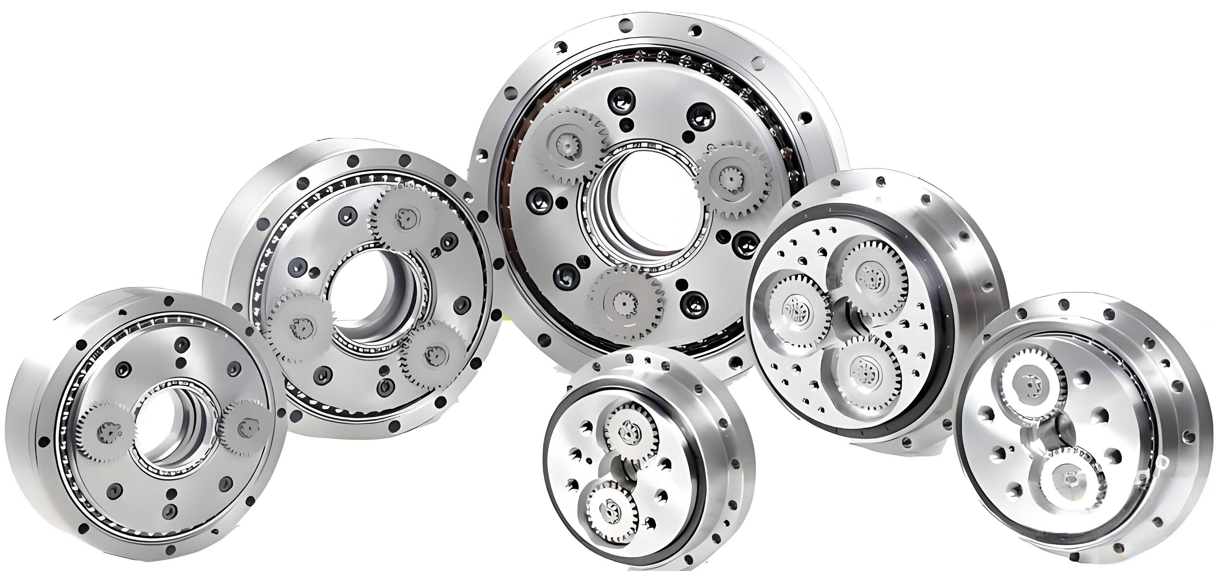
To grasp the context of this work, it is essential to understand the传动原理 of the rotary vector reducer. The system comprises components like the sun gear, planetary gears, crank shafts, cycloid wheels, and a pin housing. The first stage involves a planetary gear set where the sun gear drives multiple planetary gears, providing initial speed reduction. The second stage utilizes a cycloidal mechanism: the cycloid wheels, mounted on eccentric crank shafts, undergo epicyclic motion relative to the stationary pin housing, resulting in further减速. This dual-stage design allows the rotary vector reducer to achieve high torque output with minimal backlash, which is crucial for precision applications. The mathematical foundation for the cycloid wheel’s tooth profile is derived from epitrochoidal curves, which define the interaction with the needle bearings. The ideal tooth profile equation for the cycloid wheel is expressed as:
$$ x_c = [r_p – r_{rp} \Phi^{-1}(K_1, \phi)] \cos((1 – i_H) \phi) + [a – K_1 r_{rp} \Phi^{-1}(K_1, \phi)] \cos(i_H \phi) $$
$$ y_c = [r_p – r_{rp} \Phi^{-1}(K_1, \phi)] \sin((1 – i_H) \phi) – [a – K_1 r_{rp} \Phi^{-1}(K_1, \phi)] \sin(i_H \phi) $$
where \(\Phi^{-1}(K_1, \phi) = \sqrt{1 + K_1^2 – 2K_1 \cos \phi}\). In these equations, \(r_p\) represents the分布圆半径 of the needle bearings, \(r_{rp}\) is the needle radius, \(i_H\) denotes the relative transmission ratio between the cycloid wheel and needles, \(K_1\) is the short幅系数, \(\phi\) is the啮合相位角, and \(a\) is the eccentric distance. These parameters are critical for defining the geometry of the cycloid wheel in any rotary vector reducer. By parameterizing these variables, I can automate the modeling process, ensuring consistency and accuracy across different designs. This approach not only saves time but also allows for easy modifications to meet specific performance requirements in various rotary vector reducer applications.
SolidWorks provides a robust platform for CAD modeling, and its API (Application Programming Interface) enables二次开发 through OLE (Object Linking and Embedding) technology. In my project, I utilized VB.net as the programming language within the Visual Studio 2010 environment to create a standalone executable application. The choice of VB.net stems from its compatibility with SolidWorks API and its ability to facilitate rapid development of user-friendly interfaces. The API object hierarchy in SolidWorks includes core classes such as SldWorks (the main application), ModelDoc2 (for model documents), and FeatureManager (for managing features like sketches and extrusions). By calling these API functions programmatically, I can control SolidWorks operations from an external application, enabling automated modeling of the cycloid wheel. Among the various二次开发 methods, I opted for the parameter-driven approach, where key dimensions are defined as variables that users can input via a graphical interface. This method is particularly suited for the cycloid wheel in a rotary vector reducer due to its repetitive structural patterns and variable sizes, allowing for efficient customization without rewriting code.
The parametric design process for the cycloid wheel involves several steps, starting with the creation of a user interface and culminating in automated model generation. I developed an application named “CycloidWheelDesigner.exe” that provides a clear interface divided into sections for齿形参数 (tooth profile parameters),结构参数 (structural parameters), an example image area, and a storage information zone. Users input values such as the number of teeth, eccentric distance, and wheel thickness, and the application communicates with SolidWorks to generate the 3D model. The code implementation focuses on converting the mathematical equations into a series of coordinate points, which are then used to create spline curves for the tooth profile. For instance, the tooth profile equation is discretized into multiple points (e.g., 20 points per tooth) to approximate the curve accurately within SolidWorks. Key code snippets include initializing the SolidWorks connection, defining parameters, and executing features like sketching, patterning, extrusion, and hole-cutting. Below is a summary of the main parameters used in the design, presented in a table format to enhance clarity:
| Parameter | Symbol | Description | Typical Range |
|---|---|---|---|
| Needle Distribution Circle Radius | \(r_p\) | Radius where needle bearings are positioned | 50-200 mm |
| Needle Radius | \(r_{rp}\) | Radius of individual needle bearings | 2-10 mm |
| Short幅系数 | \(K_1\) | Coefficient affecting tooth curvature | 0.8-1.2 |
| Eccentric Distance | \(a\) | Offset for crank shaft mounting | 1-5 mm |
| Number of Teeth | \(Z_c\) | Teeth on cycloid wheel | 20-100 |
| Transmission Ratio | \(i_H\) | Ratio relative to needle gear | 10-100 |
After coding, the application was tested with the RV110E rotary vector reducer as a case study. This model is commonly used in industrial robots, and its cycloid wheel has specific dimensions that serve as a benchmark. By inputting the parameters into “CycloidWheelDesigner.exe”, I triggered the automatic modeling process in SolidWorks. The software generated a complete 3D model of the cycloid wheel, including features like the external tooth profile, crank shaft holes, central sun gear hole, and扇形安装孔 (sector mounting holes). The entire process takes only a few minutes, compared to hours of manual design, demonstrating the efficiency of this parametric approach for rotary vector reducer components. The generated model was saved in a designated directory, allowing for further analysis or integration into larger assemblies. This step underscores the practical benefits of二次开发 in accelerating the design cycle for rotary vector reducers, enabling rapid prototyping and iteration.
To validate the accuracy of the parametrically designed cycloid wheel, I conducted a comparative analysis with a physical counterpart. Using a NIKON VMZ-R4540 high-precision image measuring instrument, which has a最小读取单位 of 0.1 μm, I measured the actual cycloid wheel from an RV110E rotary vector reducer. The measurement involved capturing thousands of data points from the wheel’s轮廓线,曲柄轴孔, and中心轴孔 at a step size of 0.05 mm. These points were imported into SolidWorks to create a point cloud model, which represents the真实 geometry of the physical component. By comparing this point cloud with the parametrically generated model, I assessed discrepancies in shape and dimensions. Additionally, I calculated mass and moment of inertia for both models after assigning material properties (QT450-10 steel with elasticity modulus of 169 GPa, density of 7,060 kg/m³, and Poisson’s ratio of 0.257). The results are summarized in the table below, highlighting the close alignment between the two models:
| Model Type | Mass (kg) | Moment of Inertia (×10⁻³ kg·m²) | Notes |
|---|---|---|---|
| Parametric Model | 0.7231 | 2.993 | Based on ideal tooth profile |
| Measured Point Cloud Model | 0.7177 | 2.968 | Includes real-world modifications |
The slight differences in mass and inertia arise because the physical cycloid wheel undergoes修型 (profile modifications) and齿轮磨合 (gear run-in) during manufacturing, whereas the parametric model assumes an ideal geometry. This validation confirms that the二次开发 approach produces models that are sufficiently accurate for design purposes, with deviations within acceptable limits for most rotary vector reducer applications. Furthermore, the parametric model can be easily adjusted to incorporate修型 factors if needed, providing flexibility for优化. This step is crucial for ensuring that the design tools developed here can reliably support the production of high-performance rotary vector reducers, where precision is paramount for reducing backlash and improving efficiency.
Beyond the immediate case study, the parametric design methodology has broader implications for the rotary vector reducer industry. By enabling rapid modeling, it facilitates iterative design processes, allowing engineers to explore multiple configurations quickly. For example, changes in the偏心距离 or齿数 can be tested to optimize torque transmission or reduce weight. The use of SolidWorks API also opens doors for integrating this tool into larger digital twin frameworks, where the cycloid wheel model can be simulated under dynamic loads using finite element analysis (FEA). To illustrate the mathematical rigor involved, consider the derivation of the tooth profile equation from fundamental principles of epicyclic motion. The cycloid wheel in a rotary vector reducer follows a path defined by the superposition of rotations, which can be expressed using transformation matrices. Starting with the position vector of a point on the wheel relative to the crank shaft, we have:
$$ \mathbf{r} = \begin{bmatrix} a \cos(\theta) \\ a \sin(\theta) \end{bmatrix} + \begin{bmatrix} r \cos(\psi) \\ r \sin(\psi) \end{bmatrix} $$
where \(\theta\) is the crank angle and \(\psi\) is the wheel rotation angle. The relationship between these angles is given by the transmission ratio: \(\psi = i_H \theta\). Substituting and simplifying leads to the parametric equations earlier. This mathematical foundation ensures that the parametric model adheres to the theoretical requirements of the rotary vector reducer mechanism. Additionally, I explored the impact of parameter variations on performance metrics. For instance, increasing the短幅系数 \(K_1\) can enhance tooth strength but may affect smoothness of engagement. Such trade-offs can be analyzed systematically using the parametric tool, as shown in the table below for different design scenarios:
| Design Scenario | \(K_1\) Value | Tooth Stress (Estimated MPa) | Engagement Smoothness | Suitability for Rotary Vector Reducer |
|---|---|---|---|---|
| Standard | 1.0 | 150 | High | General purpose |
| High Strength | 1.2 | 120 | Medium | High-load applications |
| Low Vibration | 0.8 | 180 | Very High | Precision systems |
In conclusion, this research demonstrates the effectiveness of parametric design for cycloid wheels in rotary vector reducers through SolidWorks二次开发. The developed application, “CycloidWheelDesigner.exe”, streamlines the modeling process by allowing users to input key parameters and automatically generate accurate 3D models. Validation against high-precision measurements of an RV110E cycloid wheel confirmed the model’s reliability, with minor deviations attributable to real-world manufacturing adjustments. The rotary vector reducer benefits greatly from such tools, as they reduce design time, enhance consistency, and support optimization efforts. Future work could extend this approach to other components of the rotary vector reducer, such as the crank shafts or pin housing, creating a comprehensive parametric design suite. Moreover, integrating machine learning algorithms could enable自动优化 of parameters based on performance targets, further advancing the development of next-generation rotary vector reducers. As industries continue to demand higher precision and efficiency, methodologies like this will play a pivotal role in accelerating innovation and ensuring the rotary vector reducer remains a cornerstone of modern mechanical systems.
The implications of this work extend beyond academic circles into practical manufacturing environments. For instance, in the production of rotary vector reducers for robotic arms, rapid prototyping of cycloid wheels can significantly缩短 lead times and reduce costs. The parametric design tool allows for customization based on specific application needs, such as adjusting the齿形 to minimize backlash in high-precision assemblies. Additionally, the use of SolidWorks API ensures compatibility with existing CAD workflows, making adoption seamless for engineering teams. From a technical perspective, the mathematical models underlying the cycloid wheel design are critical for achieving optimal performance. The tooth profile equations ensure proper meshing with needle bearings, which is essential for the smooth operation of the rotary vector reducer. By parameterizing these equations, I have created a flexible framework that can adapt to various design constraints, whether for compact rotary vector reducers in medical devices or heavy-duty versions in industrial machinery. This adaptability highlights the versatility of the rotary vector reducer as a transmission solution, and the parametric design approach reinforces its advantages in customizable engineering.
To further elaborate on the technical details, let’s consider the code implementation for generating the tooth profile. In VB.net, the key steps involve connecting to SolidWorks, defining the spline points, and executing the建模 commands. The pseudocode below outlines the process, emphasizing the use of API functions to interact with SolidWorks objects. This code snippet illustrates how the parametric design is operationalized, ensuring that the cycloid wheel model is built programmatically rather than manually. Such automation is a game-changer for designing complex components like those in a rotary vector reducer, where manual errors can lead to performance issues. By leveraging二次开发, I have enabled a repeatable and scalable design process that can be applied to any variant of the rotary vector reducer, from small-scale models to large industrial units. This capability is particularly valuable in today’s fast-paced manufacturing landscape, where agility and precision are key competitive advantages.
In summary, the parametric design of cycloid wheels represents a significant advancement in the engineering of rotary vector reducers. Through this project, I have shown how SolidWorks二次开发 can be harnessed to create efficient, accurate, and user-friendly design tools. The validation process using high-precision measurement instruments adds credibility to the results, assuring that the models are fit for practical use. As the demand for rotary vector reducers grows in sectors like automation and renewable energy, such innovative design methodologies will be essential for meeting evolving technical requirements. I encourage further research into integrating these tools with simulation software for holistic design analysis, ultimately pushing the boundaries of what rotary vector reducers can achieve in terms of performance and reliability. This work underscores my commitment to advancing mechanical design through technology, and I look forward to seeing its impact on the future of rotary vector reducer applications worldwide.