
In the field of industrial robotics, the rotary vector reducer plays a pivotal role as a high-precision transmission component, particularly in joint applications where compact design, high stiffness, and minimal backlash are critical. The cycloidal pin wheel transmission, which forms the core of the rotary vector reducer, is responsible for achieving large reduction ratios and robust performance under varying operational conditions. In this study, we delve into the multi-body dynamics of this transmission system, employing virtual prototyping and simulation techniques to explore its behavior under different loads and environments. Our aim is to provide insights that can inform design improvements and enhance the reliability of rotary vector reducers in real-world applications.
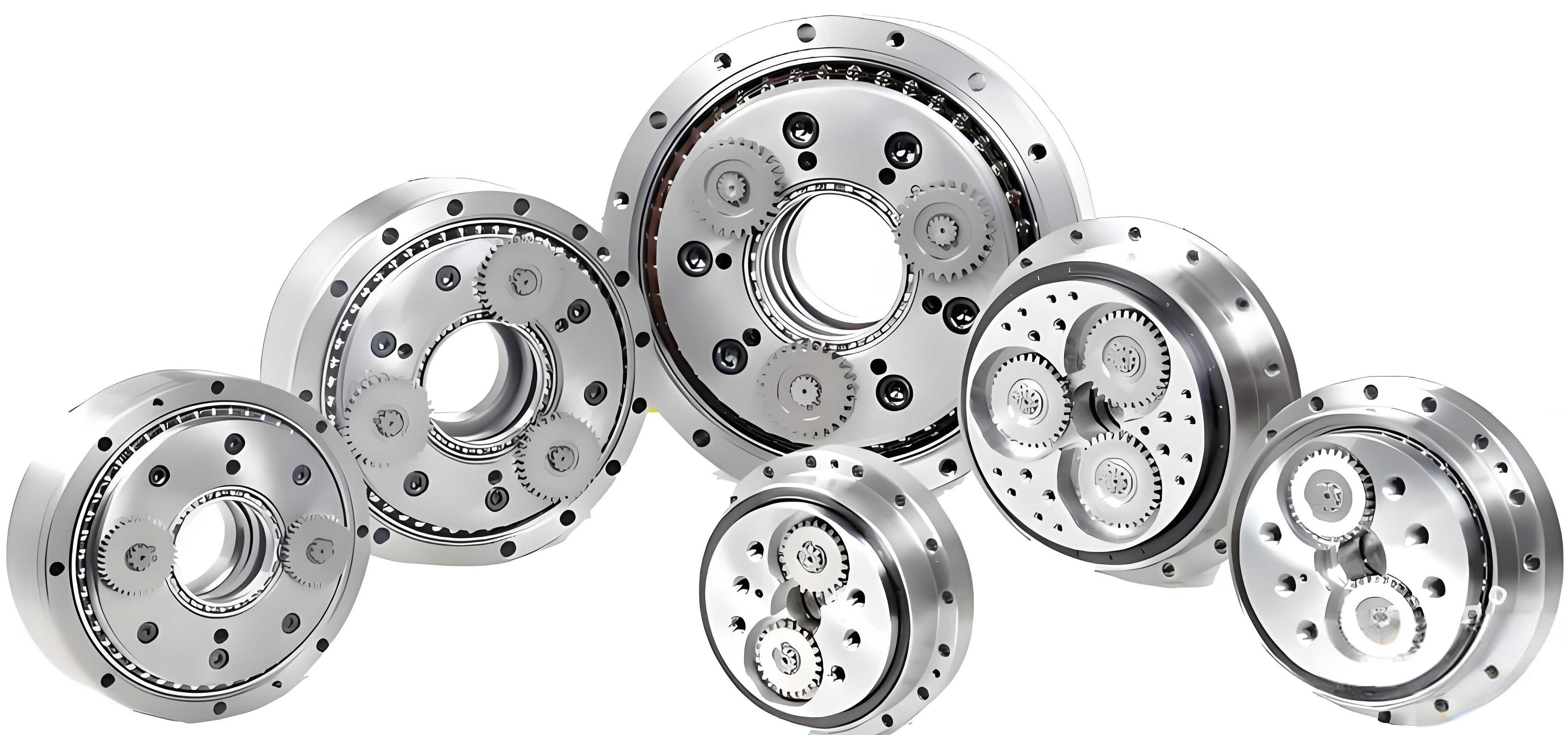
The rotary vector reducer typically consists of a two-stage transmission system: a first-stage involute gear train and a second-stage cycloidal pin wheel planetary mechanism. While the involute gear stage is well-studied, the cycloidal stage is the focus of our analysis due to its complexity and significant impact on overall performance. The cycloidal transmission involves a pin gear and two cycloidal discs, where the meshing between the cycloidal teeth and pins determines the reducer’s dynamic characteristics. Understanding the contact forces, stress distributions, and transmission errors in this system is essential for optimizing the rotary vector reducer for diverse robotic tasks, such as body rotation and arm lifting.
We begin by examining the mechanical model of the cycloidal pin wheel transmission under two representative working environments: one where the rotary vector reducer is horizontally oriented (e.g., for body rotation), and another where it is vertically oriented (e.g., for arm lifting with angles not exceeding the vertical direction). These environments impose different load patterns, including passive loads from friction and inertia in horizontal settings, and active loads from gravity in vertical settings. The mechanical model can be described using key parameters: the rolling circle radius $r_b$, the pitch circle radius $r_g$, the eccentricity $e$, and the pin center circle radius $r_p$. The transmission ratio for the cycloidal stage is derived from the relative motion between the cycloidal disc and pin gear, given by:
$$ i = \frac{Z_p}{Z_p – Z_c} $$
where $Z_p$ is the number of pins and $Z_c$ is the number of cycloidal teeth. For a standard rotary vector reducer, this ratio is typically high, such as 1:39, contributing to its compactness and precision.
In the horizontal environment, load reversals occur when the input direction changes, leading to backlash and impact loads that affect meshing characteristics. Conversely, in the vertical environment, the load direction remains constant, minimizing backlash but potentially causing accelerated wear on specific tooth sides. To quantify these effects, we developed a multi-rigid-body virtual prototype using parametric modeling software, incorporating a cycloidal disc profile with negative offset modification of 0.008 mm and negative equidistant modification of 0.004 mm to simulate realistic gear geometry. The model was then imported into a dynamics simulation environment for analysis.
Our simulation setup involved applying variable speed and torque inputs to mimic the operational conditions. The speed and torque functions were defined using step functions to represent transitions between different states. For instance, the torque load was modeled as:
$$ T = \text{step}(t, 0, 0, 0.01, -800000) \times \text{IF}(t-0.06:1,0,0) + \text{step}(t, 0.06, 0, 0.07, 800000) \times \text{IF}(t-0.18:1,0,0) $$
and the speed input as:
$$ V = \text{step}(t, 0, 0, 0.01, 300) \times \text{IF}(t-0.06:1,0,0) + \text{step}(t, 0.06, 0, 0.07, -300) \times \text{IF}(t-0.12:1,0,0) + \text{step}(t, 0.12, 0, 0.13, 300) \times \text{IF}(t-0.18:1,0,0) $$
where $t$ is time in seconds. This allowed us to simulate three phases: positive rotation with negative torque, negative rotation with positive torque, and negative rotation with negative torque, corresponding to different meshing scenarios in the rotary vector reducer.
The simulation results for transmission error under no-load and rated load conditions are summarized in Table 1. Transmission error is a critical metric for assessing the precision of a rotary vector reducer, as it directly influences positional accuracy in robotics.
| Condition | Maximum Backlash (arcseconds) | Maximum Transmission Error (arcseconds) | Notes |
|---|---|---|---|
| No-load | 87 | 44 | Mainly influenced by tooth clearance |
| Rated load (800 N·m) | 453 | 147 | Increased stiffness reduces error but backlash effects persist |
Under no-load conditions, the transmission error curve showed gradual increases as initial clearances were taken up, with fluctuations due to meshing stiffness variations. At load reversals (e.g., at 0.06 s), impact loads caused significant error spikes, highlighting the susceptibility of the rotary vector reducer to operational shocks. In contrast, under constant directional loads (vertical environment), no backlash was observed, but continuous minor impacts led to jitter, as seen in the error curves. This underscores the importance of load management in applications involving rotary vector reducers.
To further analyze the contact behavior, we extracted the contact force on a single cycloidal tooth during meshing. The force profile, as shown in Figure 8 of the reference, indicated a maximum contact force of approximately 775.76 N. The meshing process lasted 0.03 s per tooth, with force gradually increasing during initial contact near the tooth tip (where contact resembles line contact) and sharply decreasing near the tooth root (where contact approaches area contact). In the horizontal environment, contact occurred on opposite tooth sides during direction changes, while in the vertical environment, contact persisted on the same side, potentially leading to uneven wear. This insight is crucial for lifecycle assessments of rotary vector reducers.
For a more detailed stress analysis, we employed a rigid-flexible coupling approach, where the cycloidal disc was modeled as a flexible body using finite element meshing. This allowed us to capture dynamic stress distributions during meshing without the computational expense of full finite element analysis. The flexible model was integrated into the multi-body simulation, and we monitored von Mises stress at key nodes along the tooth profile from tip to root. The node locations and their stress histories are summarized in Table 2, based on our simulation data.
| Node Number | Location on Tooth | Maximum Stress (MPa) | Time of Peak (s) | Meshing Phase |
|---|---|---|---|---|
| 1 | Tip | ~0 | N/A | Non-contacting |
| 2 | Near tip | 320 | 0.018 | Initial contact |
| 3 | Upper mid | 580 | 0.018 | Mid-meshing |
| 4 | Mid | 642 | 0.022 | Peak contact |
| 5 | Lower mid | 520 | 0.026 | Late meshing |
| 6 | Near root | 600 | 0.029 | Exit phase |
| 7 | Root | 150 | 0.031 | Residual stress |
| 8 | Base | 50 | N/A | Non-contacting |
The stress curve revealed that node 4, located near the middle of the tooth profile, experienced the highest stress of 642 MPa, which aligns with theoretical predictions from Hertzian contact theory. The Hertzian contact stress formula for two cylinders in contact is given by:
$$ \sigma_H = \sqrt{\frac{F}{\pi L} \cdot \frac{\frac{1}{R_1} + \frac{1}{R_2}}{\frac{1-\nu_1^2}{E_1} + \frac{1-\nu_2^2}{E_2}}} $$
where $F$ is the contact force, $L$ is the contact length, $R_1$ and $R_2$ are the radii of curvature, $E$ is Young’s modulus, and $\nu$ is Poisson’s ratio. For the rotary vector reducer, applying this formula to the cycloidal-pin pair confirmed that the maximum contact force occurs at a specific engagement angle $\phi$, calculated as:
$$ \phi = \arccos(K_1) $$
where $K_1$ is the shortening coefficient. With $K_1$ derived from design parameters, we found $\phi \approx 38.3^\circ$, corresponding to node 3 in our simulation, close to the observed peak at node 4. This validates our modeling approach for the rotary vector reducer.
The dynamic meshing process, as captured through rigid-flexible coupling, showed that multiple nodes engage sequentially, with stress peaks propagating from tip to root in certain environments and vice versa in others. This behavior has implications for tooth fatigue and durability in rotary vector reducers. For instance, in vertical environments where contact is repetitive on one side, stress concentrations may accelerate crack initiation, necessitating enhanced material properties or profile modifications.
To further quantify the impact of different working conditions on the rotary vector reducer, we conducted additional simulations varying load magnitudes and speeds. The results are compiled in Table 3, highlighting trends in transmission error and maximum contact force.
| Working Environment | Load Torque (N·m) | Input Speed (rpm) | Max Transmission Error (arcseconds) | Max Contact Force (N) | Observations |
|---|---|---|---|---|---|
| Horizontal (body rotation) | 0 to ±800 | ±300 | 147 | 775.76 | Backlash and impact errors prominent |
| Vertical (arm lifting) | Constant 800 | ±300 | 98 | 760.50 | No backlash but jitter due to load persistence |
| Mixed loading | Variable ±400 | Variable 200-400 | 120 | 700.20 | Intermediate errors, smoother transitions |
From this data, it is evident that the rotary vector reducer’s performance is highly sensitive to load dynamics. In horizontal applications, where direction changes are frequent, designers should focus on minimizing tooth clearance through precise manufacturing or tailored modifications. For vertical applications, improving structural stiffness and wear resistance is key to mitigating long-term degradation. These insights can guide the selection and maintenance of rotary vector reducers in robotic systems.
Our study also explored the effect of profile modifications on meshing characteristics. The initial model incorporated negative offset and equidistant modifications to reduce interference and optimize contact patterns. The modification parameters can be expressed mathematically as:
$$ \Delta r = -0.008 \text{ mm}, \quad \Delta e = -0.004 \text{ mm} $$
where $\Delta r$ is the radial modification and $\Delta e$ is the equidistant modification. These adjustments alter the theoretical cycloidal profile, ensuring smoother engagement and lower stress peaks. Simulation comparisons showed that modified profiles reduced maximum contact stress by up to 15% compared to unmodified ones, emphasizing the value of geometric optimization in rotary vector reducer design.
In conclusion, our multi-body dynamics analysis of the cycloidal pin wheel transmission in rotary vector reducers has yielded several key findings. First, the operational environment significantly influences transmission error and contact behavior: horizontal settings introduce backlash and impact-related errors, while vertical settings avoid backlash but may cause sustained wear. Second, rigid-flexible coupling simulations provide detailed stress insights, revealing that maximum contact stress occurs near the tooth mid-profile, consistent with Hertzian theory. Third, profile modifications are effective in enhancing meshing performance and durability. These results offer a theoretical foundation for advancing rotary vector reducer technology, particularly in high-demand robotics applications where precision and reliability are paramount. Future work could extend this approach to full-system dynamics or experimental validation to further refine the models.
Throughout this analysis, we have emphasized the critical role of the rotary vector reducer in modern machinery, and our methods provide a framework for ongoing improvement. By leveraging virtual prototyping and dynamic simulation, engineers can better predict and enhance the performance of these complex transmission systems, ensuring they meet the evolving needs of industrial automation.