
In the field of precision robotics and industrial automation, the demand for high-performance, compact, and efficient transmission systems is ever-increasing. Among various solutions, the rotary vector reducer has emerged as a critical component, particularly in robotic joints, due to its exceptional combination of high torque capacity, compact size, low backlash, and high stiffness. This article presents a comprehensive optimization design methodology for the rotary vector reducer, aiming to minimize its overall volume while satisfying stringent performance and reliability constraints. The discussion is based on a detailed analysis of its structure, working principles, design requirements, and the formulation of a mathematical optimization model. A practical design example using MATLAB software validates the approach, demonstrating its effectiveness in achieving a more compact design compared to existing references.
The core motivation for optimizing the rotary vector reducer stems from its widespread application in articulated robots. Every gram saved and every millimeter reduced in the drive unit contributes to lower inertia, higher dynamic response, and potentially lower cost. Therefore, a systematic optimization targeting minimal volume is not merely an academic exercise but a practical necessity for advancing robotic technology.
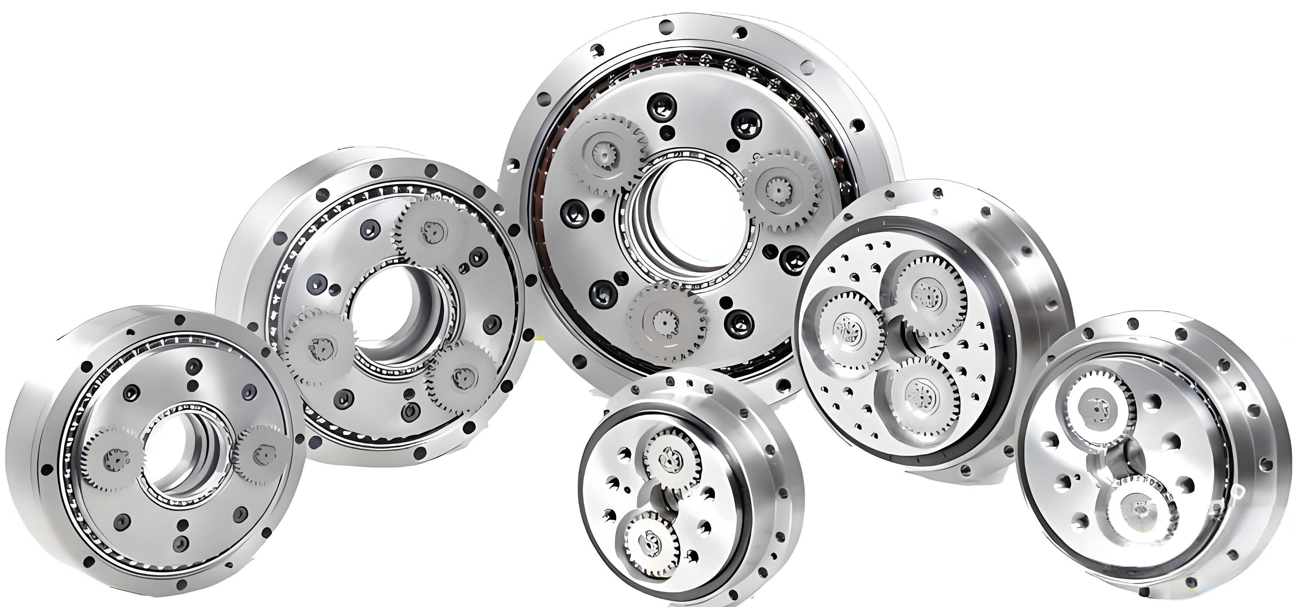
The rotary vector reducer is a sophisticated two-stage speed reduction device. Its compact design integrates a primary planetary gear stage and a secondary cycloidal pin-wheel stage. The primary stage consists of a sun gear (often integrated with the input shaft) and typically two or three planetary gears arranged symmetrically. This stage provides the initial speed reduction. The secondary stage, which is the hallmark of the rotary vector reducer, comprises a set of crankshafts connected to the planetary gears, cycloidal discs (or摆线轮), a stationary pin gear (or针齿轮), and an output carrier (or行星架). The unique motion conversion in this stage provides high reduction ratios, exceptional torque density, and minimal backlash.
The working principle of the rotary vector reducer is elegant. Input rotation is transmitted to the sun gear. The meshing with the planetary gears completes the first reduction. The planetary gears, which are connected via splines to the crankshafts, transfer this motion to the second stage. The rotation of the crankshafts causes an eccentric motion (revolution) of the cycloidal discs. Since the pin gear is fixed, this revolution forces the cycloidal discs to rotate slightly in the opposite direction (self-rotation). This self-rotation is then transmitted back to the crankshafts, causing them to revolve around the central axis. Finally, this revolution is captured by the output carrier, resulting in a low-speed, high-torque output. The total reduction ratio \( i_{total} \) is a product of the two stages:
$$ i_{total} = i_{1} \times i_{2} = \left(1 + \frac{z_{2}}{z_{1}}\right) \times \frac{z_{p}}{z_{p} – z_{c}} $$
Where \( z_{1} \) is the sun gear tooth count, \( z_{2} \) is the planetary gear tooth count, \( z_{p} \) is the number of pins in the pin gear, and \( z_{c} \) is the number of lobes on the cycloidal disc (typically \( z_{c} = z_{p} – 1 \)). For a standard configuration with fixed pin gear and output carrier, the secondary stage ratio is \( z_{p}/(z_{p} – z_{c}) = z_{p} \).
Design Requirements and Constraints for the Rotary Vector Reducer
To ensure the rotary vector reducer meets practical application needs, the optimization must be governed by a set of rigorous design requirements. These criteria balance performance, longevity, and physical dimensions.
| Design Requirement | Target Value or Condition | Rationale |
|---|---|---|
| Overall Transmission Efficiency | > 85% | Ensures energy-efficient operation, critical for battery-powered robots. |
| Torsional Backlash | Minimized, typically < 1 arc-minute for precision grades. | Essential for positional accuracy and repeatability in robotics. |
| Service Life | Exceeds 10,000 hours under rated load. | Guarantees reliability and reduces maintenance needs in industrial settings. |
| Primary Design Objective | Minimize total volume or mass. | Reduces robot arm inertia and enables more compact joint design. |
| Primary Stage Reduction Ratio | Should not be too small (\( i_{1} \geq 1.5 \)). | Leverages the high torque capacity of the cycloidal stage effectively. |
| Transmission Ratio Accuracy | Error between calculated and nominal ratio ≤ 5%. | Ensures predictable speed and torque output. |
| Geometric Relationship | Gear center distance \( a_{0} \) = (50% to 60%) of Pin Gear Radius \( r_{p} \). | Optimizes force distribution and structural layout within the rotary vector reducer. |
Material selection and heat treatment are paramount for meeting these requirements, especially for wear resistance and fatigue life. Key components like gears and cycloidal discs are often made from alloy steels such as 20Cr or GCr15, subjected to carburizing or quenching processes to achieve high surface hardness (HRC 56-62).
Mathematical Optimization Model Formulation
The core of this work is to formulate a single-objective, constrained nonlinear optimization problem for the rotary vector reducer. The goal is to find the set of design parameters that minimizes volume while satisfying all mechanical and geometric constraints.
Objective Function and Design Variables
The overall volume of the rotary vector reducer is complex to model directly. A key geometric driver is the center distance \( a_{0} \) of the primary spur gear stage, as it directly influences the radial dimensions of both stages. Minimizing \( a_{0} \) effectively leads to a more compact rotary vector reducer. Therefore, the objective function is defined as:
$$ \text{Minimize: } f(\mathbf{X}) = a_{0} = \frac{m (z_{1} + z_{2})}{2} $$
Where the design variable vector \( \mathbf{X} = [m, z_{1}, z_{2}] \). Here, \( m \) is the gear module (a discrete standard value), \( z_{1} \) is the sun gear tooth number, and \( z_{2} \) is the planetary gear tooth number. Other parameters like pin count \( z_{p} \), pin radius \( r_{rp} \), and cycloidal disc width \( b_{c} \) become intermediate variables determined by subsequent constraints and relationships.
Constraint Conditions
The design must adhere to multiple engineering constraints derived from strength, geometry, and performance.
1. Bending and Contact Fatigue Strength for Primary Gears:
The spur gears must withstand bending and contact stresses. The constraints are derived from standard AGMA/Lewis equations.
$$ g_{1}(\mathbf{X}): m \ge \sqrt[3]{\frac{2 K T_{1} Y_{Fa} Y_{Sa}}{\phi_{d} z_{1}^{2} [\sigma_{F}]}} \quad \text{(Bending Strength)} $$
$$ g_{2}(\mathbf{X}): m z_{1} \ge 2.32 \sqrt[3]{\frac{K T_{1} (i_{2}+1) Z_{E}^{2}}{\phi_{d} i_{2} [\sigma_{H}]^{2}}} \quad \text{(Contact Strength)} $$
Where:
- \( K \): Load factor (accounts for dynamic loads).
- \( T_{1} \): Input torque on sun gear, \( T_{1} = 9.55 \times 10^{6} \times \frac{P}{n_{input}} \), with \( n_{input} = n_{output} \times i_{total} \).
- \( Y_{Fa}, Y_{Sa} \): Tooth form factor and stress correction factor. They are functions of \( z_{1} \) and must be obtained via interpolation from handbook data in the computational algorithm.
- \( \phi_{d} \): Face width factor, set to 0.3 for initial design.
- \( [\sigma_{F}], [\sigma_{H}] \): Allowable bending and contact stress for the selected material.
- \( Z_{E} \): Elastic coefficient, \( \approx 189.9 \sqrt{\text{MPa}} \) for steel-steel contact.
- \( i_{2} = z_{2}/z_{1} \): Primary stage ratio.
2. Transmission Ratio Constraint:
The designed total ratio must closely match the required nominal ratio \( i_{req} \).
$$ g_{3}(\mathbf{X}): \left| \frac{i_{total} – i_{req}}{i_{req}} \right| \le 0.05 \quad \text{(5% tolerance)} $$
With \( i_{total} = (1 + z_{2}/z_{1}) \times z_{p} \). The pin count \( z_{p} \) is itself subject to geometric constraints related to the cycloidal stage.
3. Geometric and Assembly Constraints for Primary Stage:
$$ g_{4}(\mathbf{X}): z_{1} \ge 17 \quad \text{(to avoid undercutting for standard gear teeth)} $$
$$ g_{5}(\mathbf{X}): z_{1} \text{ must be even and a multiple of the number of crankshafts (typically 2)} $$
$$ g_{6}(\mathbf{X}): i_{2} = \frac{z_{2}}{z_{1}} \ge 1.5 \quad \text{(to ensure significant first-stage reduction)} $$
4. Cycloidal Stage Constraints and Relationships:
The design of the secondary cycloidal stage in the rotary vector reducer is governed by specific formulas. The pin gear center radius \( r_{p} \) is a function of output torque:
$$ r_{p} = k_{r} \sqrt[3]{T_{output}} \quad \text{where } k_{r} \in [0.85, 1.3] \text{ is an empirical coefficient, and } T_{output} = 9.55 \times 10^{6} \frac{P \eta}{n_{output}} $$
The overall efficiency \( \eta \) is calculated considering both gear mesh and bearing losses. A detailed formula for the complex power flow in the rotary vector reducer is:
$$ \eta = \eta_{bearings} \cdot \eta_{gears} = \eta_{B}^{n} \cdot \frac{(i_{6}^{H}-1)(i_{6}^{H}-\eta_{6}^{H} + i_{1}^{H} i_{6}^{H} \eta_{1}^{H})}{(i_{6}^{H}-\eta_{6}^{H})(i_{6}^{H}-1 + i_{1}^{H} i_{6}^{H})} $$
Where \( \eta_{B} \) is single bearing efficiency (~0.993), \( \eta_{1}^{H} \) is primary gear pair efficiency (~0.992), \( \eta_{6}^{H} \) is cycloid-pin mesh efficiency (~0.998), \( i_{1}^{H}=i_{2} \), and \( i_{6}^{H}=z_{p} \).
The critical geometric coupling constraint between the two stages is:
$$ g_{7}(\mathbf{X}): 0.5 r_{p} \le a_{0} \le 0.6 r_{p} $$
This ensures a balanced and force-optimized layout for the rotary vector reducer.
Additional cycloidal design parameters include the eccentricity \( a \) (half the crankshaft offset), the pin radius \( r_{rp} \), the shortening factor \( K_{1} \) (typically between 0.65 and 0.85), and the cycloidal disc width \( b_{c} \). These are determined by standardized design equations for cycloidal drives to ensure proper conjugation and load distribution:
$$ a = \frac{r_{p} K_{1}}{z_{p}} $$
$$ z_{c} = z_{p} – 1 $$
$$ b_{c} \approx (0.1 \text{ to } 0.15) r_{p} $$
These parameters must be checked for manufacturing feasibility and stress limits.
| Element | Description | Mathematical Expression |
|---|---|---|
| Objective | Minimize Center Distance | $$ \min f(\mathbf{X}) = \frac{m(z_{1}+z_{2})}{2} $$ |
| Design Variables | Gear Module, Sun Teeth, Planet Teeth | $$ \mathbf{X} = [m, z_{1}, z_{2}] $$ |
| Primary Constraints | Gear Strength | $$ g_{1}(m,z_{1}): m \ge \sqrt[3]{\frac{2 K T_{1} Y_{Fa} Y_{Sa}}{\phi_{d} z_{1}^{2} [\sigma_{F}]}} $$ $$ g_{2}(m,z_{1}): m z_{1} \ge 2.32 \sqrt[3]{\frac{K T_{1} (i_{2}+1) Z_{E}^{2}}{\phi_{d} i_{2} [\sigma_{H}]^{2}}} $$ |
| Ratio Constraint | Total Ratio Accuracy | $$ g_{3}(z_{1},z_{2},z_{p}): \left| \frac{(1+z_{2}/z_{1})z_{p} – i_{req}}{i_{req}} \right| \le 0.05 $$ |
| Geometric Constraints | Tooth Count & Stage Coupling | $$ g_{4}(z_{1}): z_{1} \ge 17; \quad g_{5}(z_{1}): z_{1} \text{ mod } 2 = 0 $$ $$ g_{6}(z_{1},z_{2}): z_{2}/z_{1} \ge 1.5 $$ $$ g_{7}(m,z_{1},z_{2},r_{p}): 0.5 r_{p} \le \frac{m(z_{1}+z_{2})}{2} \le 0.6 r_{p} $$ |
| Intermediate Variables | Derived from Design | $$ i_{2}=z_{2}/z_{1}; \quad a_{0}=\frac{m(z_{1}+z_{2})}{2}; \quad r_{p}=f(T_{output}); \quad etc. $$ |
Computational Implementation and Design Example
Solving this constrained nonlinear optimization problem requires computational tools. MATLAB and its Optimization Toolbox are well-suited for this task. The `fmincon` function, designed for constrained nonlinear minimization, is employed. However, a direct application is complicated by the discrete nature of some variables (like standard gear module \( m \)) and the need for integer tooth counts. Therefore, a structured, multi-step computational strategy is implemented.
The algorithm proceeds as follows:
- Parameter Initialization: Define input specifications: Rated Power \( P \), Output Speed \( n_{out} \), Required Ratio \( i_{req} \), material properties, and efficiency factors.
- Discrete Module Loop: Iterate over a feasible range of standard gear modules (e.g., 1.5, 2, 2.5, 3, 4 mm from the first series).
- Inner Optimization for Given m: For each \( m \), treat \( z_{1} \) and \( z_{2} \) as continuous variables initially and use `fmincon` to minimize \( a_{0} \) subject to constraints \( g_{1}, g_{2}, g_{6}, g_{7} \), and the ratio-dependent parts of \( g_{3} \) and \( g_{7} \). Functions for \( Y_{Fa}(z_{1}) \) and \( Y_{Sa}(z_{1}) \) are implemented as lookup tables or fitted polynomial functions within the code.
- Integerization and Feasibility Check: Round the optimized \( z_{1} \) and \( z_{2} \) to the nearest even integer for \( z_{1} \) and a corresponding integer for \( z_{2} \) that maintains the ratio. Recalculate all constraints strictly with these integer values.
- Cycloidal Parameter Calculation: Determine the pin count \( z_{p} \) from the ratio constraint \( g_{3} \) with the integer gears. Calculate \( r_{p}, a, K_{1}, b_{c} \) and verify all cycloidal design rules.
- Solution Selection: After iterating over all standard modules, select the design combination that yields the smallest feasible center distance \( a_{0} \).
This approach effectively handles the mixed-integer nature of the rotary vector reducer optimization problem.
Design Case: RV-450E Type Reducer
To validate the methodology, we apply it to the specifications of a common rotary vector reducer model:
- Rated Power, \( P \): 4.28 kW
- Output Speed, \( n_{out} \): 5 rpm
- Required Reduction Ratio, \( i_{req} \): 81
The MATLAB code, incorporating the algorithm above, is executed. The optimization seeks the minimal-volume configuration for this rotary vector reducer. The results are compared with published reference data for a similar reducer design.
| Parameter | Symbol | Unit | Optimized Design Result | Reference Design [10] | Notes / Implication |
|---|---|---|---|---|---|
| Gear Module | \( m \) | mm | 3 | 3 | Converges to same standard value. |
| Sun Gear Teeth | \( z_{1} \) | – | 18 | 18 | Satisfies undercut and evenness constraints. |
| Planet Gear Teeth | \( z_{2} \) | – | 35 | 38 | Optimization finds a slightly lower count, affecting ratio distribution. |
| Sun Gear Face Width | \( B_{1} \) | mm | 21 | 18 | Slightly wider for strength, but part of a more compact overall layout. |
| Planet Gear Face Width | \( B_{2} \) | mm | 17 | 14 | Adjusted according to load sharing. |
| Center Distance (Primary) | \( a_{0} \) | mm | 79.5 | 84 | Key Improvement: Reduction of 4.5 mm, directly contributing to smaller volume. |
| Pin Gear Tooth Count | \( z_{p} \) | – | 42 | 38 | Adjusted to achieve exact ratio with new gear pair. |
| Cycloidal Disc Teeth | \( z_{c} \) | – | 41 | 37 | \( z_{c} = z_{p} – 1 \). |
| Shortening Factor | \( K_{1} \) | – | 0.8182 | 0.7355 | Within standard range, influences tooth profile and contact. |
| Pin Gear Center Radius | \( r_{p} \) | mm | 154 | 155 | Very close, confirming torque capacity requirement. |
| Pin Radius | \( r_{rp} \) | mm | 8 | 8 | Identical, likely a standard bearing or pin size. |
| Cycloidal Disc Width | \( b_{c} \) | mm | 24 | 24 | Identical, based on bending stress criteria. |
| Crankshaft Eccentricity | \( a \) | mm | 3 | 3 | Calculated from \( a = r_{p} K_{1} / z_{p} \). |
| Achieved Total Ratio | \( i_{total} \) | – | 82.677 | 81.222 | Both within the 5% tolerance of the target 81. |
| Ratio Error | \( \Delta i \) | % | 2.07% | 0.27% | Well within the allowable 5%. |
| Stage Coupling Ratio \( a_{0}/r_{p} \) | – | – | 0.516 | 0.542 | Both satisfy the 0.5-0.6 constraint. |
The results clearly demonstrate the effectiveness of the optimization framework. The optimized design achieves a smaller center distance (79.5 mm vs. 84 mm) while satisfying all strength and performance constraints. This reduction in \( a_{0 }\) implies a more compact radial envelope for the entire rotary vector reducer assembly. The changes in tooth counts (\( z_{2} \) and \( z_{p} \)) show how the algorithm explores the design space to find a better local minimum for volume. The close agreement in most other parameters with the reference validates the physical soundness of the optimization model. The successful application of this MATLAB-based method proves it is a reliable and rational tool for the design of compact rotary vector reducers.
Conclusion and Future Perspectives
This article has detailed a systematic methodology for the optimal design of a rotary vector reducer with the primary objective of volume minimization. By establishing a precise mathematical model that incorporates critical constraints from gear tooth strength, transmission ratio accuracy, geometric compatibility, and the unique kinematics of the cycloidal stage, we have transformed the complex design problem into a tractable nonlinear optimization task. The implementation using a structured MATLAB algorithm, which cleverly handles discrete and integer variables, provides a practical computational solution.
The design case study for an RV-450E type reducer confirms the method’s validity and advantages. The optimized rotary vector reducer design shows a measurable improvement in compactness (reduced center distance) compared to a reference design, without compromising on performance indicators like ratio accuracy or strength. This underscores the value of formal optimization over traditional iterative or handbook-based design approaches for high-performance components like the rotary vector reducer.
Future work can extend this model in several directions. Multi-objective optimization could simultaneously minimize volume and maximize efficiency or minimize backlash. The model could be integrated with finite element analysis (FEA) for more precise stress and deformation constraints, particularly for the complex cycloidal disc. Furthermore, the optimization framework could be adapted to different configurations of the rotary vector reducer, such as those with a rotating pin gear housing. As robotics continues to push for lighter, stronger, and more precise actuators, advanced optimization techniques will remain indispensable in the evolution of the rotary vector reducer and similar precision transmission systems.