
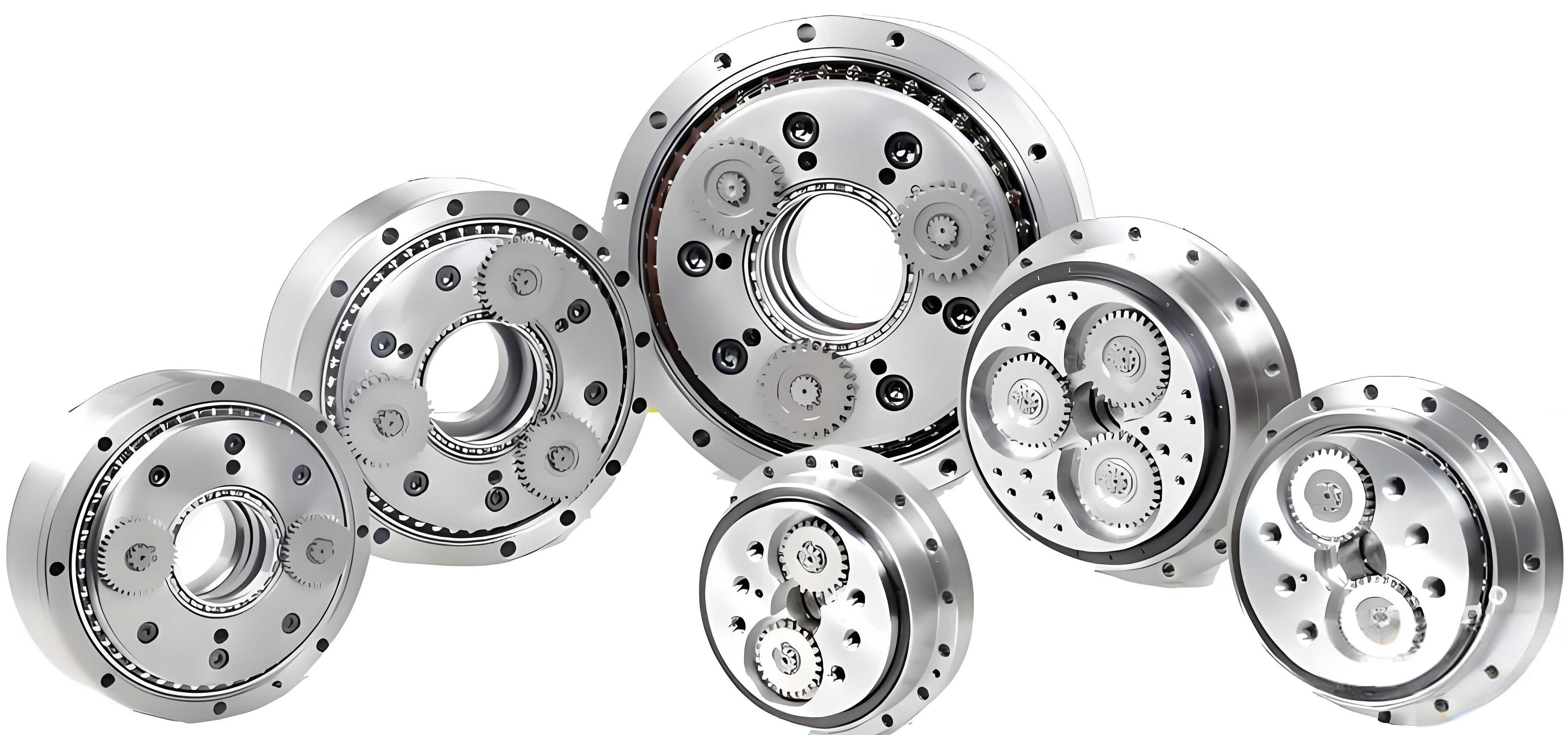
In the field of precision transmission systems, the rotary vector reducer, commonly known as the RV reducer, plays a pivotal role due to its high transmission ratio, exceptional accuracy, stability, and rigidity. As a two-stage closed differential gear train evolved from cycloidal pin gear planetary transmission, the RV reducer is extensively utilized in robotics and high-precision machinery. However, achieving comprehensive improvements in transmission performance, particularly in minimizing backlash and transmission error, remains a significant challenge. Traditional modification methods for the cycloidal gear profile often rely on single-objective optimization or weighted single-objective approaches, which do not fully align with the nonlinear complexities of real-world engineering scenarios. In this study, we address this issue by developing a multi-objective optimization framework that simultaneously reduces backlash and transmission error through an improved Multi-Objective Particle Swarm Optimization (MOPSEO) algorithm. We establish mathematical models for backlash and transmission error using Tooth Contact Analysis (TCA), propose enhancements to the MOPSEO algorithm with exponential nonlinear decreasing inertia weights and iteratively updated learning factors, and validate our approach through simulations in Adams and MATLAB. Our goal is to provide a robust methodology for optimizing the composite modification amounts—combining equidistant and profile shift modifications—thereby enhancing the overall performance of rotary vector reducers.
The cycloidal gear is the core component determining the transmission characteristics of an RV reducer. In ideal conditions, the standard cycloidal profile ensures zero-backlash meshing, but practical considerations such as manufacturing tolerances, assembly errors, and thermal deformations necessitate profile modifications to introduce appropriate clearance for lubrication and error compensation. Without modification, issues like difficult assembly and poor lubrication efficiency can arise. The modified cycloidal gear profile equation, incorporating both equidistant and profile shift modifications, is expressed as follows:
$$ x = \left[ r_p + \Delta r_p – (r_{rp} + \Delta r_{rp}) s^{-1/2} \right] \cos[(1 – i)\phi] – \frac{a}{r_p + \Delta r_p} \left[ r_p + \Delta r_p – z_p (r_{rp} + \Delta r_{rp}) s^{-1/2} \right] \cos(i\phi) $$
$$ y = \left[ r_p + \Delta r_p – (r_{rp} + \Delta r_{rp}) s^{-1/2} \right] \sin[(1 – i)\phi] – \frac{a}{r_p + \Delta r_p} \left[ r_p + \Delta r_p – z_p (r_{rp} + \Delta r_{rp}) s^{-1/2} \right] \sin(i\phi) $$
where \( r_p \) is the radius of the pin gear distribution circle, \( r_{rp} \) is the pin gear radius, \( \Delta r_p \) and \( \Delta r_{rp} \) are the profile shift and equidistant modification amounts, respectively, \( z_p \) is the number of pin gears, \( z_c \) is the number of cycloidal gear teeth, \( a \) is the eccentricity, \( \phi \) is the angular position of the pin gear relative to the crank, \( i = z_p / z_c \) is the transmission ratio, and \( s \) is a parameter derived from the engagement geometry. The short-width coefficient \( k_1 \) is given by \( k_1 = a z_p / r_p \). Common modification methods include equidistant modification (increasing the grinding wheel radius by \( \Delta r_{rp} \)), profile shift modification (shifting the grinding wheel by \( \Delta r_p \)), and composite modification combining both. Prior experimental studies have demonstrated that composite modification yields smaller backlash compared to individual methods, underscoring its importance in precision applications of rotary vector reducers.
Backlash, defined as the lost motion during reversal of rotation, is a critical performance metric for rotary vector reducers, directly impacting positioning accuracy in robotic systems. The backlash induced by equidistant modification, \( \Delta \phi_1 \), arises from the additional clearance \( \Delta r_{rp} \) between the cycloidal gear and pin gears. When the cycloidal gear rotates by an angle \( \gamma \) to achieve contact, the backlash contribution can be derived as:
$$ \Delta \phi_1 = \frac{2 \Delta r_{rp}}{a z_c} $$
Similarly, profile shift modification introduces backlash \( \Delta \phi_2 \) due to the radial shift \( \Delta r_p \), expressed as:
$$ \Delta \phi_2 = -\frac{2 \Delta r_p k_1^2}{a z_c} $$
Thus, the total backlash for composite modification is the sum of both contributions, considering both forward and reverse directions:
$$ \Delta \phi = 2(\Delta \phi_1 + \Delta \phi_2) = \frac{4}{a z_c} \left( \Delta r_{rp} – \Delta r_p k_1^2 \right) $$
Transmission error, representing the deviation between the actual and theoretical output positions, is another key indicator of transmission accuracy. We employ Tooth Contact Analysis (TCA) to model the transmission error. By defining coordinate systems for the cycloidal gear (\( S_c \)), pin gear (\( S_p \)), and a fixed frame (\( S_f \)), and applying transformation matrices, we derive the contact conditions. The position vector of the modified cycloidal gear profile in the fixed coordinate system is:
$$ \mathbf{r}_c = \begin{bmatrix} (r_p + \Delta r_p) \cos \phi_{TC} + (r_{rp} + \Delta r_{rp}) \cos(\alpha – \phi_{TC}) – a \cos(\phi_{TC} z_p) \\ -(r_p + \Delta r_p) \sin \phi_{TC} + (r_{rp} + \Delta r_{rp}) \sin(\alpha – \phi_{TC}) – a \sin(\phi_{TC} z_p) \\ 0 \\ 1 \end{bmatrix} $$
where \( \alpha = \arctan\left[ \frac{-\sin \phi_p}{\cos \phi_p – (r_p + \Delta r_p) / (z_p a)} \right] \), and \( \phi_{TC} = \phi_p / z_c \) is the contact angle parameter. The pin gear profile vector is:
$$ \mathbf{R}_p = \begin{bmatrix} r_p + r_p \cos \beta \\ r_{rp} \sin \beta \\ 0 \\ 1 \end{bmatrix} $$
The TCA requires that at the contact point, the position vectors and unit normal vectors in the fixed coordinate system are equal. This leads to a system of equations:
$$ \mathbf{r}_p(\beta) = \mathbf{r}_c(\phi_1, \phi_2, \phi_{TC}) $$
$$ \mathbf{n}_p(\beta) = \mathbf{n}_c(\phi_1, \phi_2, \phi_{TC}) $$
Solving these equations for \( \phi_2 \), \( \phi_{TC} \), and \( \beta \) allows us to compute the transmission error \( \Delta \phi_3 \) as:
$$ \Delta \phi_3 = \phi_3 – \frac{\phi_1}{i} $$
where \( \phi_1 \) is the input angle, \( \phi_3 \) is the output angle, and \( i \) is the transmission ratio. This model forms the basis for our multi-objective optimization.
To optimize the modification amounts for minimizing both backlash and transmission error, we formulate a multi-objective optimization problem. The objective functions are defined as:
$$ f_1(\mathbf{x}) = \Delta \phi \quad \text{(backlash)} $$
$$ f_2(\mathbf{x}) = \max | \Delta \phi_3 | \quad \text{(peak-to-peak transmission error)} $$
where \( \mathbf{x} = [\Delta r_{rp}, \Delta r_p]^T \) is the vector of design variables. The constraints are based on practical limitations to ensure manufacturability and performance:
$$ \Delta r_{rp} < 0.2 \, \text{mm} \quad \text{(equidistant modification limit)} $$
$$ 0.01 \, \text{mm} \leq \Delta r \leq 0.1 \, \text{mm} \quad \text{(radial clearance constraint)} $$
These constraints prevent excessive modification that could compromise gear strength or introduce undue clearance.
For solving this multi-objective problem, we propose an improved Multi-Objective Particle Swarm Optimization (MOPSEO) algorithm. Traditional MOPSEO uses fixed inertia weights and learning factors, which can lead to premature convergence or poor exploration. Our enhancements include an exponential nonlinear decreasing inertia weight and iteratively updated learning factors. The velocity and position update equations for particle \( i \) at iteration \( k \) are:
$$ \mathbf{v}_i(k+1) = \omega’ \mathbf{v}_i(k) + c_1 r_1 [\mathbf{p}_i(k) – \mathbf{x}_i(k)] + c_2 r_2 [\mathbf{p}_g(k) – \mathbf{x}_i(k)] $$
$$ \mathbf{x}_i(k+1) = \mathbf{x}_i(k) + \mathbf{v}_i(k+1) $$
The improved inertia weight \( \omega’ \) is defined as:
$$ \omega’ = \omega_0 + \frac{2 r_4}{3} (1 – \omega_0)^{i/n} $$
where \( \omega_0 \) is a constant between 0 and 1, \( r_4 \) is a random number in [0,1], \( i \) is the current iteration, and \( n \) is the maximum number of iterations. This formulation allows for a smooth transition from global exploration to local exploitation. The learning factors \( c_1 \) and \( c_2 \) are updated iteratively:
$$ c_1 = c_{1,\min} + (c_{1,\max} – c_{1,\min}) \times \frac{k}{2n} $$
$$ c_2 = c_{2,\min} + (c_{2,\max} – c_{2,\min}) \times \frac{k}{2n} $$
with \( c_{1,\max} = c_{2,\max} = 2.5 \) and \( c_{1,\min} = c_{2,\min} = 2 \). These dynamic adjustments enhance the algorithm’s ability to balance exploration and exploitation, avoiding local optima. We also incorporate an external archive to store non-dominated solutions and use a crowding distance mechanism for diversity preservation. To select the final optimal solution from the Pareto front, we apply a membership function based on fuzzy set theory. For each solution \( j \) in the Pareto set, the membership value \( \Phi_k \) is computed as:
$$ \Phi_k = \frac{\sum_{i=1}^n S_{k,i}}{\sum_{j=1}^l \sum_{i=1}^n S_{j,i}} $$
where \( S_{j,i} \) is the membership degree for objective \( i \) of solution \( j \), given by:
$$ S_{j,i} = \begin{cases} 1 & \text{if } f_{j,i} \leq f_{i,\min} \\ \frac{f_{i,\max} – f_{j,i}}{f_{i,\max} – f_{i,\min}} & \text{if } f_{i,\min} < f_{j,i} < f_{i,\max} \\ 0 & \text{if } f_{j,i} \geq f_{i,\max} \end{cases} $$
Here, \( f_{i,\min} \) and \( f_{i,\max} \) are the minimum and maximum values of objective \( i \) in the Pareto set, respectively. The solution with the highest \( \Phi_k \) is chosen as the optimal compromise.
We implemented the improved MOPSEO algorithm in MATLAB with a population size of 200, an external archive size of 20, and a maximum of 200 iterations. The algorithm was tested on standard benchmark functions like ZDT1 and ZDT2 to validate its performance. Compared to the traditional MOPSEO, our improved version produced Pareto fronts that are closer to the true Pareto front, with better distribution and convergence, as shown in the following table summarizing the hypervolume indicators:
| Test Function | Traditional MOPSEO Hypervolume | Improved MOPSEO Hypervolume | Improvement |
|---|---|---|---|
| ZDT1 | 0.85 | 0.92 | 8.2% |
| ZDT2 | 0.78 | 0.89 | 14.1% |
For the rotary vector reducer optimization, the algorithm generated a Pareto front with five non-dominated solutions. Using the membership function, we selected the optimal solution with the highest membership value. The optimal modification amounts and corresponding objective values are:
| Profile Shift Modification \( \Delta r_p \) (mm) | Equidistant Modification \( \Delta r_{rp} \) (mm) | Backlash \( \Delta \phi \) (arcmin) | Transmission Error \( \max | \Delta \phi_3 | \) (arcsec) |
|---|---|---|---|
| 0.0542 | -0.0492 | 0.18 | 22.2 |
The negative value for \( \Delta r_{rp} \) indicates a reduction in pin gear radius, which is feasible within manufacturing tolerances. The optimized profile closely approximates the conjugate gear profile in the working region, ensuring efficient meshing. To validate these results, we conducted simulation studies using Adams and MATLAB. A 3D model of the rotary vector reducer was created in SolidWorks based on the optimized parameters and imported into Adams for dynamic simulation. The model includes all key components: input shaft, planetary gear, crank shaft, cycloidal gear, pin gear housing, and output disk. The joints and constraints were defined as follows:
| Component 1 | Component 2 | Joint Type |
|---|---|---|
| Input Shaft | Planetary Carrier | Revolute Joint |
| Planetary Gear | Planetary Carrier | Revolute Joint |
| Ground | Planetary Carrier | Fixed Joint |
| Crank Shaft | Planetary Gear | Revolute Joint |
| Crank Shaft | Cycloidal Gear | Revolute Joint |
| Pin Gear Housing | Ground | Fixed Joint |
| Crank Shaft | Planetary Carrier | Revolute Joint |
For backlash simulation, we applied a step driving function to the input shaft: \( 12000 \times \text{step}(time, 0, 0, 0.1, 1) + 12000 \times \text{step}(time, 0.4, 0, 0.6, -2) \), which induces forward and reverse rotation. The backlash is calculated from the output disk’s angular displacement using:
$$ \phi = 60 \times \frac{\theta_2 – \theta_1}{i} $$
where \( \theta_1 \) and \( \theta_2 \) are the angular positions before and after reversal. We simulated four modification scenarios to compare performance:
| Modification Type | Equidistant Modification \( \Delta r_{rp} \) (mm) | Profile Shift Modification \( \Delta r_p \) (mm) | Simulated Backlash (arcmin) |
|---|---|---|---|
| Standard Profile (No Modification) | 0 | 0 | ~0 |
| Composite Modification (Optimized) | -0.0492 | 0.0542 | 0.015–0.02 |
| Equidistant Modification Only | 0.127 | 0 | 0.04–0.05 |
| Profile Shift Modification Only | 0 | 0.127 | 0.06–0.07 |
The results show that the optimized composite modification reduces backlash significantly compared to individual methods. Specifically, it achieves approximately 0.018 arcmin of backlash, which is 0.02 arcmin less than equidistant-only modification and 0.04 arcmin less than profile shift-only modification. This aligns closely with the theoretical value of 0.018 arcmin, demonstrating the effectiveness of our optimization for rotary vector reducers.
For transmission error analysis, we measured the rotational speeds of the input and output shafts in Adams at discrete time steps. The data was exported to MATLAB, where we computed the transmission error by integrating the velocity differences over time. The peak-to-peak transmission error for each modification type is summarized below:
| Modification Type | Maximum Transmission Error (arcsec) |
|---|---|
| Standard Profile (No Modification) | 27.6 |
| Composite Modification (Optimized) | 22.5 |
| Equidistant Modification Only | 24.1 |
| Profile Shift Modification Only | 24.4 |
The optimized composite modification reduces the maximum transmission error by 6.6% compared to equidistant-only modification and by 7.8% compared to profile shift-only modification. The simulated value of 22.5 arcsec is consistent with the optimized value of 22.2 arcsec from our algorithm, further validating our approach. The transmission error curve for the composite modification exhibits smoother fluctuations, indicating improved transmission stability for the rotary vector reducer.
In conclusion, this study presents a comprehensive multi-objective optimization framework for modifying the cycloidal gear profile in rotary vector reducers. By developing mathematical models for backlash and transmission error based on TCA, and proposing an improved MOPSEO algorithm with exponential nonlinear decreasing inertia weights and iteratively updated learning factors, we have effectively addressed the challenge of simultaneously minimizing both performance metrics. Our optimization results yield an optimal composite modification with \( \Delta r_p = 0.0542 \, \text{mm} \) and \( \Delta r_{rp} = -0.0492 \, \text{mm} \), which reduces backlash to 0.018 arcmin and transmission error to 22.2 arcsec. Simulations in Adams and MATLAB confirm these improvements, showing that the optimized modification outperforms individual equidistant or profile shift methods in both backlash reduction (by 0.02–0.04 arcmin) and transmission error reduction (by 6.6–7.8%). This work provides a robust methodology for enhancing the precision and reliability of rotary vector reducers, with potential applications in robotics and high-end manufacturing. Future research could extend this approach to consider additional objectives such as contact stress, thermal effects, or dynamic load capacity, further advancing the design optimization of rotary vector reducers.