
In the field of precision mechanical transmission, particularly within industrial robotics, the rotary vector reducer plays a pivotal role due to its compact structure, high transmission ratio, and exceptional accuracy. As a key component, the cycloid wheel within the rotary vector reducer is subject to various operational stresses, with spalling faults being a common failure mode that significantly impacts vibration characteristics and overall system reliability. This article delves into the vibration response of a rotary vector reducer system under cycloid wheel spalling faults, employing finite element simulation and experimental validation to elucidate the dynamic behavior. The aim is to provide insights for fault prognosis, thereby enhancing the safety and longevity of machinery utilizing rotary vector reducers.
The rotary vector reducer, often abbreviated as RV reducer, is a two-stage closed differential gear system. The first stage comprises a planetary gear set with cylindrical gears, while the second stage features a cycloid drive mechanism involving cycloid wheels, a pin gear housing, and a planetary carrier. This configuration ensures smooth torque transmission and high precision, making rotary vector reducers indispensable in applications such as robotic joints. However, during operation, internal excitations from gear meshing can induce vibrations, and faults like spalling on cycloid wheel teeth exacerbate these effects, leading to increased noise and potential system failure. Understanding the vibration characteristics under such faults is crucial for predictive maintenance.
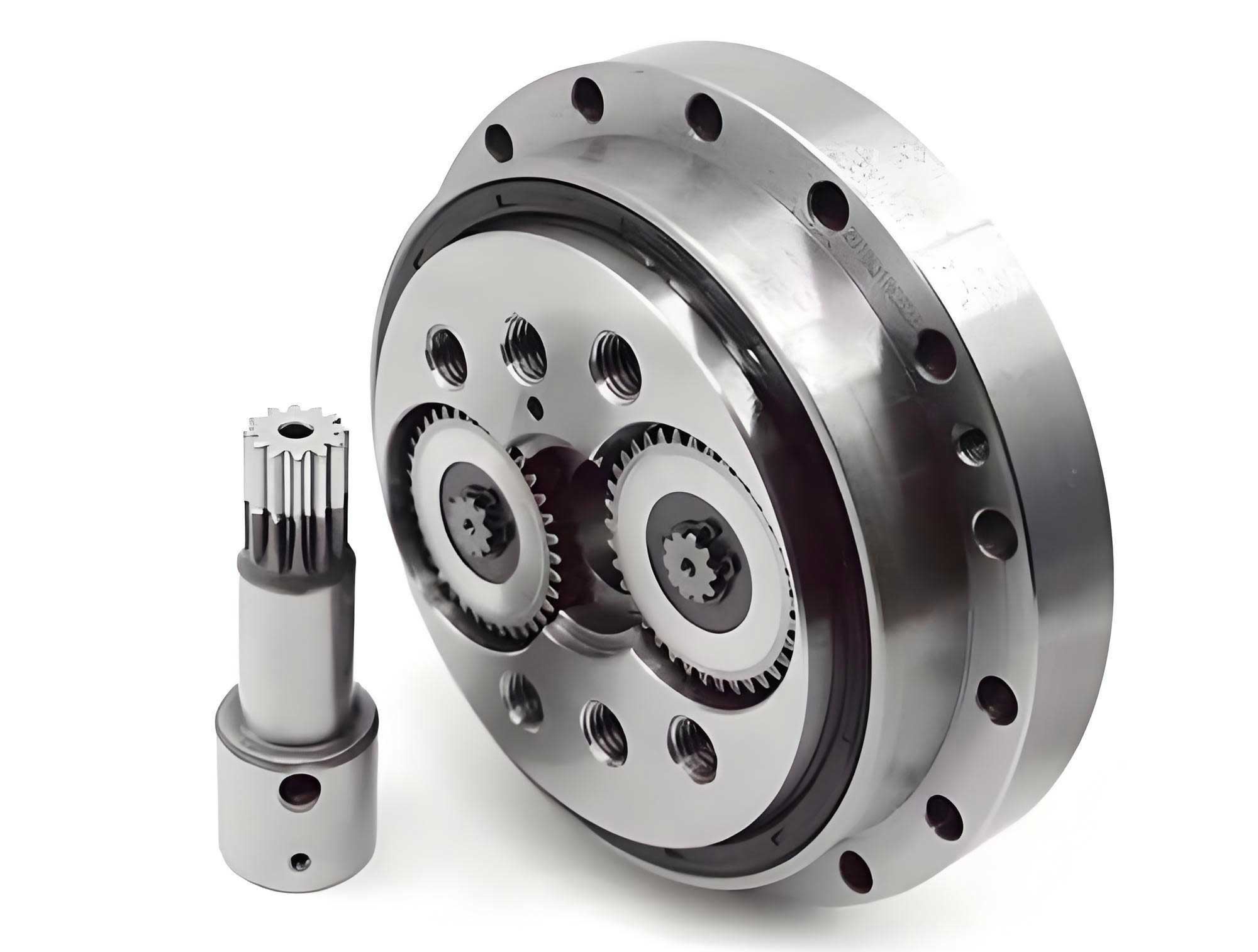
To analyze the spalling fault, a parametric model of the cycloid wheel is first established. The cycloid profile is generated by a rolling circle of radius \( r \) moving along a base circle of radius \( R \). In a Cartesian coordinate system, the parametric equations for the cycloid curve can be derived based on pure rolling motion. Let \( \theta \) be the rotation angle of the base circle, and \( \beta \) be the corresponding rotation angle of the rolling circle. From the arc length equality, we have:
$$ \beta = \frac{R}{r} \theta $$
The coordinates of a point on the cycloid are given by:
$$ x = (R + r) \cos \theta – \cos \alpha $$
$$ y = (R + r) \sin \theta + \sin \alpha $$
where \( \alpha = 2\pi – \theta – \beta \). Substituting \( \beta \), the parametric equations simplify to:
$$ x = (R + r) \cos \theta – \cos\left(1 + \frac{R}{r}\right) \theta $$
$$ y = (R + r) \sin \theta – \sin\left(1 + \frac{R}{r}\right) \theta $$
These equations are fundamental for modeling the cycloid wheel geometry in the rotary vector reducer. Using this formulation, a three-dimensional model of the cycloid drive system is created, incorporating key components like the cycloid wheels, pin gear housing, and planetary gears. The spalling fault is simulated by introducing a localized material removal on the tooth flank of the cycloid wheel, typically with a depth of 0.5 mm, to represent real-world damage scenarios.
The finite element model is developed using ABAQUS software, considering factors such as material properties, contact stiffness, and friction. The material used is structural steel, with properties summarized in Table 1. The mesh generation employs tetrahedral elements to ensure consistency and stability, resulting in over 230,000 elements for the entire system. For the spalling fault case, the mesh around the fault region is refined to capture stress concentrations accurately.
| Property | Value |
|---|---|
| Material | Steel (Structural) |
| Density, \( \rho \) (t/mm³) | \( 7.85 \times 10^{-9} \) |
| Elastic Modulus, \( E_1 \) (MPa) | \( 2.1 \times 10^{5} \) |
| Poisson’s Ratio, \( u \) | 0.3 |
The rotary vector reducer’s operational parameters are critical for simulation accuracy. Key design parameters are listed in Table 2, which influence the dynamic response. For instance, the number of teeth on the cycloid wheel and pin gear affects the meshing frequency, a vital factor in vibration analysis. The eccentricity and pitch circle diameters determine the kinematic relationships within the rotary vector reducer.
| Parameter | Value |
|---|---|
| Sun Gear Teeth | 12 |
| Planet Gear Teeth | 44 |
| Cycloid Wheel Teeth | 59 |
| Pin Gear Teeth | 60 |
| Pressure Angle (°) | 20 |
| Eccentricity (mm) | 2.4 |
| Planet Gear Width (mm) | 16 |
| Pin Gear Diameter (mm) | 10 |
| Pin Gear Center Circle Diameter (mm) | 165 |
The simulation setup involves defining analysis steps and boundary conditions. An explicit dynamics approach is used with a time length of 0.5 seconds, as detailed in Table 3. Contact pairs between components, such as the sun gear-planet gear and cycloid wheel-pin gear housing, are established with friction coefficients and contact stiffness to mimic real interactions. The pin gear housing is fixed, while the sun gear is subjected to rotational displacement to drive the system.
| Parameter | Value |
|---|---|
| Time Length (s) | 0.5 |
| Linear Bulk Viscosity Parameter | 0.06 |
| Output Interval | 1000 |
| Time Scaling Factor | 1 |
| Mass Scaling Factor | 1000 |
| Frequency | Uniform Time Intervals |
| Analysis Type | Explicit Dynamics |
Upon running the simulation, the Mises stress and acceleration responses are extracted for both fault-free and spalling fault states. For the cycloid wheel, the Mises stress under spalling fault is higher due to reduced load-bearing area, as shown in comparative cloud plots. However, for the pin gear housing, the stress variation is minimal because the fault is localized and the housing has sufficient thickness. This suggests that Mises stress alone may not be reliable for fault prognosis in rotary vector reducers.
Acceleration analysis reveals more pronounced effects. The acceleration values for both the cycloid wheel and pin gear housing are significantly higher under spalling fault conditions. For instance, the acceleration magnitude on the pin gear housing increases by an order of magnitude compared to the fault-free case. This is attributed to the impact forces generated when the faulty tooth engages with the pin gear. To quantify this, the acceleration at a point on the pin gear housing is analyzed in the time domain. After an initial transient period (0.05 seconds), a sharp peak appears around 0.28 seconds for the faulted case, with an amplitude approximately ten times greater than that in the fault-free state. This time-domain signature serves as a clear indicator of spalling fault in the rotary vector reducer.
Frequency domain analysis further enriches the understanding. Using short-time Fourier transform, the vibration signals are converted to frequency spectra. In the fault-free state, the spectrum shows dominant peaks at the meshing frequency and its harmonics. For the spalling fault case, additional sidebands emerge around the meshing frequency, spaced at intervals corresponding to the fault passage frequency. This modulation effect arises from the periodic impacts of the spalling fault on the normal meshing vibration. The fault passage frequency \( f_f \) can be estimated based on the rotary vector reducer’s kinematics. For a rotary vector reducer with input speed \( N \) rpm, the meshing frequency \( f_m \) is given by:
$$ f_m = \frac{N \times Z_s}{60} $$
where \( Z_s \) is the number of sun gear teeth. The fault passage frequency for the cycloid wheel is related to its rotational speed and the number of teeth. From the simulation, the sideband spacing is observed to be around 1454 Hz, which aligns with the expected fault frequency. The presence of these sidebands, along with increased amplitude and prolonged meshing cycles, provides robust features for fault detection in rotary vector reducers.
To validate the simulation findings, experimental tests are conducted on an RV reducer performance detection platform. The setup includes a drive motor, load motor, torque-speed sensors, and an IEPE triaxial accelerometer mounted on the pin gear housing. Tests are performed under identical conditions: input speed of 500 rpm and load torque of 60 Nm. The acquired vibration signals are processed to obtain frequency spectra. In the spalling fault case, the spectrum exhibits distinct peaks and sidebands similar to the simulation, albeit with smaller magnitudes due to real-world damping and noise. The fault-free spectrum shows minimal modulation, confirming the simulation’s accuracy. This experimental verification underscores the reliability of the finite element model for analyzing vibration characteristics in rotary vector reducers.
The implications of these results are substantial for predictive maintenance. By monitoring acceleration signals on the pin gear housing of a rotary vector reducer, one can detect early signs of spalling faults through time-domain impact peaks and frequency-domain sidebands. This proactive approach can prevent catastrophic failures and extend the service life of the reducer. Furthermore, the parametric models and simulation methodologies developed here can be adapted to other gear systems, enhancing overall machinery health management.
In conclusion, this study comprehensively investigates the vibration characteristics of a rotary vector reducer under cycloid wheel spalling faults. Through finite element simulation and experimental validation, it is demonstrated that spalling faults induce significant changes in acceleration responses, with time-domain impacts and frequency-domain sidebands serving as key indicators. The rotary vector reducer’s dynamic behavior is intricately linked to its geometric and operational parameters, necessitating careful modeling for accurate fault prognosis. Future work could explore advanced signal processing techniques or machine learning algorithms to automate fault diagnosis in rotary vector reducers, further advancing the field of condition-based monitoring.
From a broader perspective, the rotary vector reducer remains a critical component in high-precision applications, and understanding its failure modes is essential for innovation. By leveraging simulations and experiments, engineers can design more robust reducers and develop effective maintenance strategies. The insights gained from this research contribute to the ongoing efforts to improve the reliability and efficiency of rotary vector reducers in industrial automation and robotics.
To summarize the key equations and relationships, Table 4 provides a concise overview of the formulas used in this analysis. These equations form the mathematical foundation for modeling and interpreting the vibration behavior of rotary vector reducers.
| Equation Description | Formula |
|---|---|
| Cycloid Parametric Equations | $$ x = (R + r) \cos \theta – \cos\left(1 + \frac{R}{r}\right) \theta $$ $$ y = (R + r) \sin \theta – \sin\left(1 + \frac{R}{r}\right) \theta $$ |
| Meshing Frequency | $$ f_m = \frac{N \times Z_s}{60} $$ |
| Fault Passage Frequency (Estimated) | $$ f_f = \frac{N \times Z_c}{60 \times k} $$ where \( Z_c \) is cycloid wheel teeth and \( k \) is a kinematic factor |
| Acceleration Response (Time Domain) | $$ a(t) = A \delta(t – t_0) + \text{background vibration} $$ for impact events |
| Frequency Modulation | $$ S(f) = \sum_{n} C_n \delta(f – f_m \pm n f_f) $$ for sideband formation |
Ultimately, the rotary vector reducer’s performance under fault conditions highlights the importance of integrated design and maintenance practices. By continuing to explore these vibration characteristics, the industry can move towards smarter, more resilient systems that minimize downtime and maximize productivity. The rotary vector reducer, as a cornerstone of modern machinery, deserves ongoing research to unlock its full potential in evolving technological landscapes.