
The Rotary Vector (RV) reducer, a pivotal component in industrial robotics, plays a crucial role in ensuring high precision, high stiffness, and reliable torque transmission. It typically features a two-stage reduction mechanism: a first-stage involute planetary gear train and a second-stage cycloidal pinwheel drive. The inherent multi-tooth contact of the standard cycloidal profile contributes significantly to its high load-bearing capacity. However, in practical applications, specific tooth profile modifications are applied to the cycloid disc to compensate for manufacturing errors and ensure proper lubrication. This modification often reduces the number of simultaneously engaged teeth, consequently diminishing the overall load capacity of the reducer. Therefore, optimizing the fundamental parameters of the **rotary vector reducer**’s cycloidal drive is of paramount engineering importance.
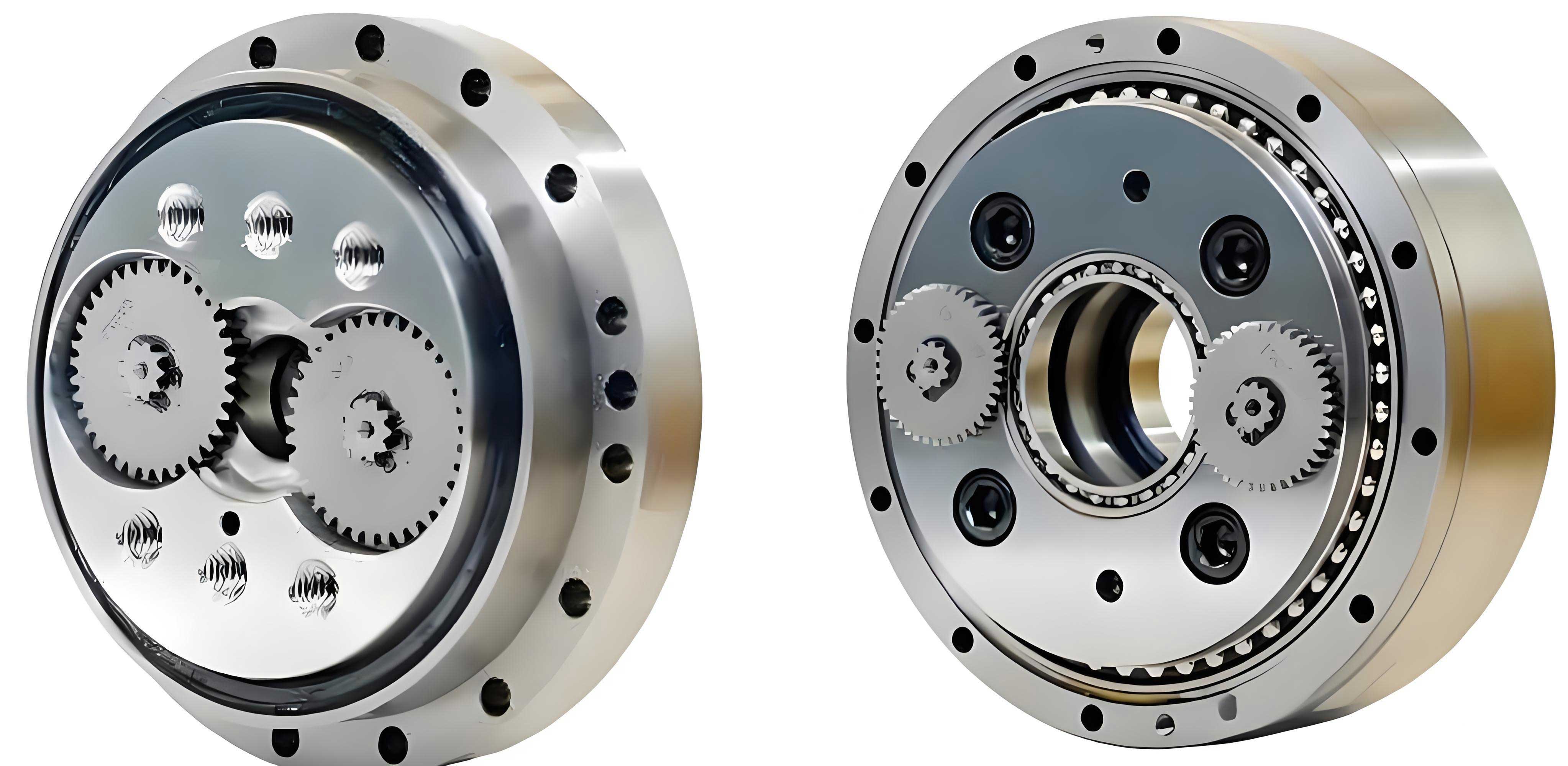
This article focuses on enhancing the load capacity of the **rotary vector reducer** by systematically optimizing the basic parameters of its cycloidal pinwheel pair. Under the premise of standardized external dimensions for the reducer, the eccentricity and the pin radius are selected as design variables. An optimization model is established with the maximization of load capacity as the primary objective. Given the complex, non-explicit relationship between load capacity and these parameters, an improved fitness function for a Genetic Algorithm (GA) is employed to facilitate an efficient search for the optimal solution. A case study is conducted on an RV-20E model reducer, followed by the fabrication of optimized components, assembly, and experimental validation to confirm the performance improvements.
Transmission Analysis and Load Capacity Formulation
The kinematic chain of an **rotary vector reducer** begins with an input shaft driving a sun gear. This sun gear meshes with multiple planetary gears, constituting the first-stage planetary reduction. Each planetary gear is connected to a crankshaft. The rotation of the crankshafts drives the cycloid discs, which mesh with stationary pins housed in a pin gear casing (cycloid housing). This interaction between the eccentric motion of the crankshaft and the fixed pins forces the cycloid discs to undergo a slow revolution relative to the casing. This motion is transferred to the output flange, completing the second-stage cycloidal reduction. The overall high reduction ratio is achieved through this compounded mechanism.
The cycloidal pinwheel pair is the core torque amplification stage. Analyzing its force transmission is key to understanding load capacity. During operation, contact forces arise between the pins and the cycloid disc tooth flanks. The maximum contact force, $F_{max}$, occurs at the pin with the longest moment arm, $L_{max}$, relative to the center of the cycloid disc’s base circle, $O_c$. Assuming the force at any other engaged pin $i$ is proportional to its moment arm $L_i$, the force $F_i$ can be expressed as:
$$F_i = F_{max} \cdot \frac{L_i}{r_c’}$$
where $r_c’$ is the radius of the cycloid disc’s base circle ($r_c’ = \overline{O_cP}$).
The torque transmitted by a single cycloid disc, $T_e$, is the sum of the moments from all engaged pins ($z_p$ is the number of pins):
$$T_e = \sum_{i} F_i L_i = \sum_{i} F_{max} \cdot \frac{L_i}{r_c’} \cdot L_i = \frac{F_{max}}{r_c’} \sum_{i} L_i^2$$
Through geometric relations in the cycloidal drive, it can be shown that $\sum_{i} L_i^2 = \frac{1}{4} z_p r_c’^2$. Substituting this into the equation yields a simplified relation:
$$T_e = \frac{1}{4} F_{max} z_p r_c’$$
Accounting for load distribution between the two cycloid discs in an **rotary vector reducer** and defining the overall output torque (load capacity) as $T$, with $T_e \approx 0.55T$, we derive the link between output torque and maximum contact stress:
$$T = \frac{T_e}{0.55} = \frac{F_{max} z_p r_c’}{2.2}$$
Further incorporating the geometric relation $r_c’ = k_1 r_p$, where $k_1$ is the shortening coefficient and $r_p$ is the pin distribution circle radius, the final expression for the **rotary vector reducer** load capacity is:
$$T = \frac{F_{max} k_1 z_p r_p}{2.2}$$
This equation highlights that $T$ is directly proportional to $F_{max}$. However, determining $F_{max}$ from the basic design parameters ($a$, $r_{rp}$) is non-trivial, as it involves complex contact mechanics and depends on the number of engaged teeth after profile modification.
Mathematical Optimization Model
To enhance the **rotary vector reducer**’s performance, an optimization model targeting the cycloidal pair’s basic parameters is constructed. The goal is to maximize load capacity while adhering to critical design constraints.
Design Variables
Within the standardized envelope of the **rotary vector reducer**, the eccentricity $a$ and the pin radius $r_{rp}$ are the most influential basic parameters on load capacity. Thus, the design variable vector $\mathbf{X}$ is defined as:
$$\mathbf{X} = [a, \quad r_{rp}]^T$$
Objective Function
The primary objective is to maximize the output torque $T$, which represents the **rotary vector reducer**’s load capacity:
$$\text{Maximize: } f(\mathbf{X}) = T(a, r_{rp})$$
Constraints
The optimization must satisfy multiple engineering constraints to ensure feasibility, strength, and longevity:
1. Geometric Parameter Bounds: The shortening coefficient $k_1 = a z_p / r_p$ and the pin diameter coefficient $k_2 = 2 r_{rp} / (r_p \sin(\pi / z_p))$ must remain within standard practical ranges to ensure proper tooth form and pin strength.
$$g_1(\mathbf{X}) = k_{1x} – \frac{a z_p}{r_p} \leq 0, \quad g_2(\mathbf{X}) = \frac{a z_p}{r_p} – k_{1y} \leq 0$$
$$g_3(\mathbf{X}) = k_{2x} – \frac{2 r_{rp}}{r_p \sin(\pi / z_p)} \leq 0, \quad g_4(\mathbf{X}) = \frac{2 r_{rp}}{r_p \sin(\pi / z_p)} – k_{2y} \leq 0$$
2. Undercutting Prevention: The pin radius must be smaller than the minimum absolute curvature radius of the theoretical cycloid profile, $|\rho_0|_{min}$, to avoid undercutting or pointing of the cycloid tooth.
$$g_5(\mathbf{X}) = r_{rp} – |\rho_0|_{min} < 0$$
3. Contact Stress Limit: The maximum Hertzian contact stress $\sigma_{H,max}$ between the pin and the cycloid disc must not exceed the allowable stress $\sigma_{HP}$. For a given torque $T$, $F_{max}$ can be calculated, and the contact stress is evaluated.
$$g_6(\mathbf{X}) = 0.418 \sqrt{\frac{F_{max} E_e}{b_c \rho_{ei}}} – \sigma_{HP} \leq 0$$
where $E_e$ is the equivalent elastic modulus, $b_c$ is the cycloid disc width, and $\rho_{ei}$ is the equivalent curvature radius at the contact point.
4. Bearing Life Requirement: The calculated life $L_{10}$ of the crankshaft bearings (needle roller bearings) must meet or exceed the required service life $L_p$.
$$g_7(\mathbf{X}) = \frac{10^6}{60 n} \left( \frac{C}{P} \right)^\epsilon – L_p \leq 0$$
where $C$ is the dynamic load rating, $P$ is the equivalent dynamic load on the bearing, $n$ is the relative speed, and $\epsilon$ is the life exponent.
Genetic Algorithm with Enhanced Fitness Evaluation
Since the functional relationship $T(a, r_{rp})$ is implicit and cannot be expressed in a simple closed form, a metaheuristic optimization approach is adopted. The Genetic Algorithm is chosen for its robustness in handling nonlinear, constrained problems. A key challenge is efficiently evaluating the objective function $T$ for a given set $(a, r_{rp})$, as it requires verifying constraints $g_6$ and $g_7$ which themselves depend on $T$.
An improved fitness evaluation procedure is developed to address this circular dependency and accelerate the search:
Step 1: For an individual defined by $(a, r_{rp})$, check constraints $g_1$ to $g_5$. If violated, assign a low fitness.
Step 2: If geometric constraints are satisfied, initiate an inner search loop for the maximum feasible torque $T$. Start with an initial guess $T_{00}$.
Step 3: Calculate the resulting $F_{max}$ from $T_{00}$, then compute the ratios $R_1 = \sigma_{H,max} / \sigma_{HP}$ and $R_2 = L_{10} / L_p$. Find $R_{max} = \max(R_1, R_2)$.
Step 4: Implement a decision logic to adjust $T$:
- If $0.995 \leq R_{max} \leq 1$, the torque $T_{00}$ is feasible and near the limit. Set $T = T_{00}$.
- If $R_{max} < 0.995$, the design is under-stressed. Increase $T$ using an adaptive step until $R_{max}$ enters the target band.
- If $R_{max} > 1$, the design is over-stressed. Decrease $T$ using an adaptive step (larger step if $R_{max} > 1.5$) until $R_{max} \leq 1$. If it falls below 0.995, use a bisection method between the last feasible $T$ and the current $T$ to find the optimal value on the constraint boundary.
Step 5: The resulting $T$ from this inner loop is the maximum load capacity for the given $(a, r_{rp})$ that satisfies all constraints. This value $T$ is used as the fitness score for the GA individual.
This method allows the GA to efficiently and accurately evaluate the load capacity associated with each parameter set without requiring an explicit formula.
Case Study: Optimization of an RV-20E Reducer
The proposed methodology is applied to optimize an RV-20E type **rotary vector reducer**. The fixed parameters from the original design are listed below:
| Parameter | Symbol | Value | Unit |
|---|---|---|---|
| Number of Cycloid Teeth | $z_c$ | 39 | – |
| Number of Pins | $z_p$ | 40 | – |
| Pin Distribution Circle Radius | $r_p$ | 51.5 | mm |
| Cycloid Disc Width | $b_c$ | 10.2 | mm |
| Original Eccentricity | $a_0$ | 1.0 | mm |
| Original Pin Radius | $r_{rp0}$ | 2.5 | mm |
The bounds for the design variables, derived from standard design practice, are: $a \in [0.85, 1.15]$ mm and $r_{rp} \in [2.50, 4.05]$ mm.
The GA is configured with a population size of 50, 500 generations, a crossover probability of 0.4, and a mutation probability of 0.1. The optimization converged to the following optimal parameters:
| Optimal Parameter | Symbol | Optimal Value | Unit |
|---|---|---|---|
| Eccentricity | $a_{opt}$ | 0.96 | mm |
| Pin Radius | $r_{rp_{opt}}$ | 2.52 | mm |
The corresponding maximum output torque (load capacity) was calculated as $T_{opt} = 293.34$ N·m. For comparison, the load capacity of the original design (with standard cycloid profile) was numerically simulated to be $T_{orig} = 263.92$ N·m. This represents a significant performance improvement:
$$\text{Load Capacity Increase} = \frac{T_{opt} – T_{orig}}{T_{orig}} \times 100\% \approx 11.15\%$$
Experimental Validation and Results
To validate the optimization results, new cycloid discs and pin gears were manufactured based on the optimized parameters ($a=0.96$ mm, $r_{rp}=2.52$ mm). The cycloid discs employed the same segmented profile modification method as the original design to ensure fairness in comparison. The optimized components were assembled into complete RV-20E reducers.
Performance testing was conducted on a ZRT-II type comprehensive performance test bench for robotic precision reducers. Tests were performed according to standard procedures. The reducer’s output speed was set to 15 RPM. Key performance indicators—transmission efficiency, temperature rise, and noise—were measured under light load (50 N·m), rated load (167 N·m), and heavy load (400 N·m) conditions. Each test was repeated three times, and average values were taken.
The comparative experimental results are summarized in the table below and illustrated in the subsequent figures.
| Load Condition | Metric | Original Design | Optimized Design | Improvement |
|---|---|---|---|---|
| Rated Load (167 N·m) | Efficiency (%) | 80.5 | 82.8 | +2.3% |
| Temperature Rise (°C) | 15.8 | 15.1 | -0.7°C | |
| Noise (dB) | 73 | 72 | -1 dB | |
| Heavy Load (400 N·m) | Efficiency (%) | 81.2 | 84.4 | +3.2% |
| Temperature Rise (°C) | 25.5 | 24.5 | -1.0°C | |
| Noise (dB) | 78 | 76 | -2 dB |
The experimental data clearly demonstrates the superiority of the optimized **rotary vector reducer**:
- Enhanced Efficiency: The increase in transmission efficiency (2.3% at rated load, 3.2% at heavy load) indicates lower power loss, directly linked to improved mechanical design and reduced internal friction/losses.
- Reduced Thermal Load: The lower temperature rise under load signifies better heat dissipation characteristics and reduced internal energy loss, contributing to long-term reliability.
- Improved Acoustic Performance: The reduction in operating noise, particularly under heavy load (-2 dB), suggests smoother meshing, better load distribution among teeth, and reduced vibration, which is a critical quality indicator for precision reducers.
The fact that performance gains are more pronounced under heavy load conditions strongly validates that the optimization successfully enhanced the fundamental load-carrying capacity and robustness of the **rotary vector reducer**.
Conclusion
This study presents a systematic method for optimizing the basic parameters of the cycloidal pinwheel pair to enhance the load capacity of a **rotary vector reducer**. A mathematical model was established with eccentricity and pin radius as design variables, aiming to maximize output torque subject to geometric, strength, and life constraints. An improved Genetic Algorithm fitness evaluation routine was developed to efficiently handle the implicit relationship between design variables and load capacity.
Applied to an RV-20E reducer, the optimization yielded a new parameter set (eccentricity = 0.96 mm, pin radius = 2.52 mm), which theoretically increased the load capacity by 11.15%. Experimental validation on manufactured prototypes confirmed substantial practical improvements: at rated load, transmission efficiency increased by 2.3%, temperature rise decreased by 0.7°C, and noise level reduced by 1 dB. The performance advantages were even more significant under heavy load conditions.
The results demonstrate that targeted optimization of fundamental cycloidal drive parameters is a highly effective approach for boosting the performance and load-bearing capability of **rotary vector reducers**, contributing to the development of more powerful and reliable robotic drive systems.