
The bending and torsional vibration displacements of the concentrated mass points on each drive shaft obtained by simulation are taken as the displacement boundary conditions of the finite element model, and the drive shaft is parameterized modeled and solved based on the programming language to obtain the transverse and torsional coupled dynamic stresses of each shaft section, thus the dangerous areas of each shaft section can be identified.
Maximum dynamic stress of each propeller shaft under 1-8 gear.From the variation trend, the maximum dynamic stress of each shaft system gradually decreases with the increase of gear.The maximum dynamic stress occurs on the second drive shaft under gear 1.
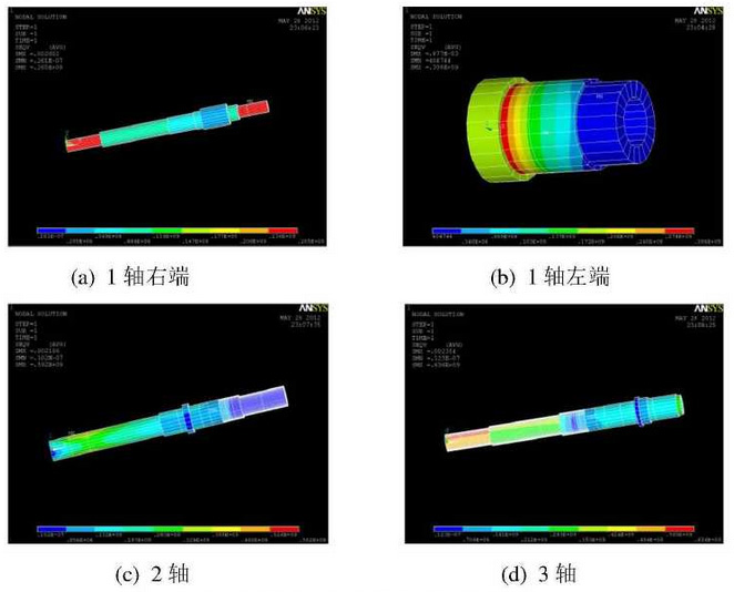
The stress cloud diagram of each shaft system at a certain moment under 1st gear is given.It can be seen from the diagram that the maximum dynamic stress of the right-end shaft system of 1-axis occurs in the shaft section between the sun wheels of two planetary drives and between the input connecting disc and bearing 1; the maximum dynamic stress of the left-end shaft system of 1-axis occurs in the shaft section between bearing 3 and G01; the maximum dynamic stress of 2-axis occurs between G1 and G3 gears; and the maximum dynamic stress of 3-axis occurs between the left-end output disc and bearing 8.