
In this comprehensive exploration, I will detail the methodology for parametric modeling of involute spur gears within a CAD environment, specifically focusing on how the tooth count fundamentally influences the modeling approach. As a mechanical design engineer, I have extensively utilized parametric techniques to enhance efficiency and accuracy in gear design. Spur gears are among the most common power transmission elements, and their precise digital representation is paramount for simulation, manufacturing, and assembly. The core premise of parametric modeling lies in defining a model through a set of controlling parameters; altering these parameters automatically regenerates the entire geometry. This article will systematically cover the theoretical foundations, practical implementation steps, and critical considerations based on tooth count range, all from my first-hand perspective. I will employ numerous formulas and tables to encapsulate the key relationships, ensuring that the concept of spur gears is reiterated throughout to emphasize their centrality in mechanical systems.
Parametric modeling represents a paradigm shift in computer-aided design (CAD). Instead of creating static geometries, I define features—such as extrusions, cuts, and patterns—whose dimensions are linked to algebraic expressions or parameters. This allows for rapid design iteration. For instance, changing the module or number of teeth of a spur gear instantly updates all dependent geometries like the pitch diameter, addendum circle, and tooth profile. In advanced CAD systems like Siemens NX (formerly Unigraphics or UG), this is facilitated through an “Expressions” editor where I can declare variables and mathematical relationships. The primary advantage is the creation of a single, intelligent model that can spawn an entire family of spur gears. This is particularly valuable for standardization and customization in gearbox design.
To establish a parametric model for a standard involute spur gear, I must first identify and define the fundamental set of independent parameters. From these, all other geometric properties are derived. The table below summarizes these essential parameters, which form the backbone of any spur gear model.
| Parameter Name | Common Symbol | Description |
|---|---|---|
| Number of Teeth | \( z \) | The count of teeth on the gear. This is a primary driver of gear size and ratio. |
| Module | \( m \) | A scaling factor that defines the size of the tooth. It is essentially the ratio of pitch diameter to tooth count. |
| Pressure Angle | \( \alpha \) | The angle between the line of action and the line tangent to the pitch circle. Standard values are 20° or 14.5°. |
| Face Width | \( b \) | The axial length of the gear teeth. |
| Addendum Coefficient | \( h_a^* \) | Factor to determine addendum height, typically 1.0 for standard gears. |
| Dedendum (or Clearance) Coefficient | \( c^* \) | Factor to determine dedendum height, ensuring clearance. Often 0.25 for standard full-depth teeth. |
Using these six basic parameters, I can calculate every critical dimension required to model the spur gear. The following set of derived formulas is indispensable. Note that all dimensions are typically in millimeters when using the module system.
Pitch Circle Radius: This is the reference circle for defining tooth spacing.
$$ r = \frac{m \cdot z}{2} $$
Base Circle Radius: The circle from which the involute tooth profile is developed. The geometry of spur gears hinges on this.
$$ r_b = r \cdot \cos(\alpha) = \frac{m \cdot z}{2} \cdot \cos(\alpha) $$
Addendum (Tooth Tip Height): The radial distance from the pitch circle to the top of the tooth.
$$ h_a = h_a^* \cdot m $$
Dedendum (Tooth Root Height): The radial distance from the pitch circle to the bottom of the tooth space.
$$ h_f = (h_a^* + c^*) \cdot m $$
Tip Circle (Addendum Circle) Radius:
$$ r_a = r + h_a = \frac{m \cdot z}{2} + h_a^* \cdot m $$
Root Circle (Dedendum Circle) Radius:
$$ r_f = r – h_f = \frac{m \cdot z}{2} – (h_a^* + c^*) \cdot m $$
Now, a crucial aspect that dictates the modeling strategy for spur gears is the relationship between the root circle radius \( r_f \) and the base circle radius \( r_b \). The active tooth profile of a standard involute spur gear is the involute curve only from the base circle outward. If the root circle lies inside the base circle (\( r_f < r_b \)), the tooth profile between the root and base circles is not an involute but a trochoid or fillet curve, often approximated in CAD. This condition is directly governed by the number of teeth. I can derive the critical tooth count by setting \( r_f > r_b \) and solving for \( z \).
Starting with the inequality:
$$ r_f > r_b $$
Substituting the formulas:
$$ \frac{m \cdot z}{2} – (h_a^* + c^*) \cdot m > \frac{m \cdot z}{2} \cdot \cos(\alpha) $$
Dividing both sides by \( m \) (a positive value):
$$ \frac{z}{2} – (h_a^* + c^*) > \frac{z}{2} \cdot \cos(\alpha) $$
Rearranging to solve for \( z \):
$$ \frac{z}{2} (1 – \cos(\alpha)) > (h_a^* + c^*) $$
$$ z > \frac{2 (h_a^* + c^*)}{1 – \cos(\alpha)} $$
Defining the critical number of teeth \( z_c \) as the minimum integer satisfying this:
$$ z_c = \left\lceil \frac{2 (h_a^* + c^*)}{1 – \cos(\alpha)} \right\rceil $$
where \( \lceil \cdot \rceil \) denotes the ceiling function. For standard full-depth spur gears with \( \alpha = 20° \), \( h_a^* = 1 \), and \( c^* = 0.25 \):
$$ z_c = \left\lceil \frac{2 (1 + 0.25)}{1 – \cos(20°)} \right\rceil = \left\lceil \frac{2.5}{1 – 0.9396926} \right\rceil = \left\lceil \frac{2.5}{0.0603074} \right\rceil \approx \lceil 41.45 \rceil = 42 $$
This calculation leads to a pivotal conclusion for modeling spur gears:
- If the actual number of teeth \( z > z_c \) (e.g., \( z \geq 43 \) for standard 20° gears), then \( r_f > r_b \). The entire tooth flank from root to tip is an involute curve (with a possible fillet at the very root for manufacturing).
- If \( z \leq z_c \) (but typically not less than, say, 17 to avoid undercutting with standard cutters), then \( r_f < r_b \). The tooth profile consists of two distinct segments: an involute curve from the base circle to the tip circle, and a non-involute, approximated curve (like a radial line or a spline) from the base circle down to the root circle.
This dichotomy necessitates two slightly different parametric modeling procedures within CAD software. I must create two master or template models to efficiently generate all possible spur gears.
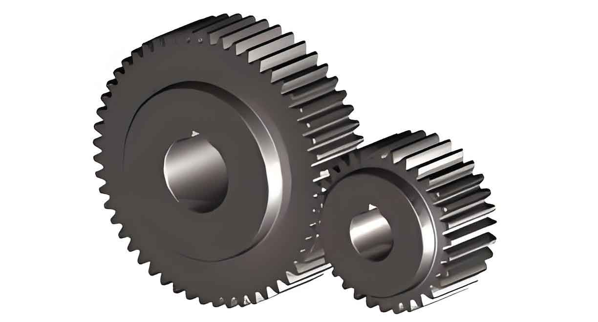
The image above illustrates a classic example of a machined spur gear. The precise involute profile on the tooth flanks is critical for smooth, efficient meshing with minimal noise and wear. In my parametric models, I strive to replicate this geometry accurately, accounting for the base circle limitation.
Having established the theoretical groundwork, I will now describe the step-by-step parametric modeling process for involute spur gears in a UG/NX environment. The overarching strategy is to create a solid gear blank (a cylinder) and then subtract tooth material defined by a sketched tooth space profile. This profile is constructed using a precisely generated involute curve. The entire process is driven by the parameter list created in the Expressions editor.
Step 1: Creating the Parameter List (Expressions). I start by defining all parameters and derived dimensions as named expressions. In NX, I can either type them directly into the Expressions dialog or, more efficiently, create a text file (.exp) and import it. This list becomes the single source of truth for the model. A comprehensive expression set for a spur gear includes not only the six basic parameters but also all calculated radii and angles for the involute. For example:
// Basic Parameters
z = 45          // Number of teeth
m = 2           // Module (mm)
alpha = 20      // Pressure Angle (deg)
b = 20          // Face Width (mm)
ha_star = 1.0   // Addendum Coefficient
c_star = 0.25   // Dedendum Coefficient

// Derived Geometric Parameters
r = m * z / 2                       // Pitch Radius
rb = r * cos(alpha)                 // Base Radius
ha = ha_star * m                    // Addendum
hf = (ha_star + c_star) * m         // Dedendum
ra = r + ha                         // Tip Radius
rf = r - hf                         // Root Radius

// Involute Generation Parameters
t = 0            // Parameter for Law Curve (0 to 1)
ang_start = 0    // Start angle for involute (rad)
ang_end = pi()/2 // End angle for involute (rad)
// Parametric equations for involute in XY plane
xt = rb * (cos(t*ang_end) + (t*ang_end)*sin(t*ang_end))
yt = rb * (sin(t*ang_end) - (t*ang_end)*cos(t*ang_end))
This parametric setup allows me to change, for instance, `z` from 45 to 30, and upon update, the entire gear model will rebuild accordingly.
Step 2: Creating the Gear Blank. Using the `Cylinder` command, I create a solid cylinder. For the diameter, I input `2*ra` (the tip diameter), and for the height, I input `b` (the face width). The base point is at the absolute origin (0,0,0). This cylinder represents the outermost material of the spur gear.
Step 3: Generating the Involute Curve. This is a critical step. In NX, I use the `Law Curve` tool. I define the X, Y, and Z components of the curve as functions of a parameter `t` (which varies from 0 to 1). Using the expressions defined earlier (`xt`, `yt`, and `zt=0`), I generate the exact involute profile emanating from the base circle. The curve will start at the base circle and extend outward beyond the tip circle to ensure proper trimming later.
Step 4: Constructing a Single Tooth Space Profile (Sketch). This step differs based on the tooth count relative to the critical value \( z_c \). I create a new sketch on a datum plane (e.g., the XY plane). In this sketch, I first project or draw the key circles as reference curves: the tip circle (diameter `2*ra`), root circle (diameter `2*rf`), pitch circle (diameter `2*r`), and base circle (diameter `2*rb`). I also include the generated involute curve.
| Condition (Tooth Count) | Tooth Profile Segment from Root to Base Circle | Sketch Construction Method for Tooth Space |
|---|---|---|
| \( z > z_c \) (e.g., z=45) | Involute | 1. Trim the involute curve between the root and tip circles. 2. Mirror this trimmed involute about the tooth centerline (line at angular offset of \( \pi/z \) radians from origin). 3. Close the profile with arc segments along the root and tip circles. |
| \( z \leq z_c \) (e.g., z=20) | Non-involute (approximated) | 1. Trim the involute curve between the base and tip circles. 2. For the segment from root circle to base circle, draw an approximate curve. This is often a radial line tangent to the root fillet or a spline connecting the root circle to the start of the involute at the base circle. The exact geometry may depend on the cutter simulation. 3. Mirror the combined profile and close with arcs. |
To find the tooth centerline for mirroring, I draw a line from the sketch origin. The angular position of one tooth space boundary is determined by the circular tooth thickness. For a standard gear, the tooth thickness on the pitch circle is \( \pi m / 2 \). The corresponding angle is \( \pi / z \) radians. So, I rotate a line from the horizontal axis by this angle to serve as the mirror axis.
Step 5: Creating the First Tooth Space (Extrude Cut). Once the closed tooth space profile is complete, I exit the sketch and use the `Extrude` command. I select the profile, set the extrusion limits to be symmetric about the sketch plane (e.g., start = -b/2, end = b/2), and choose the `Subtract` Boolean operation to cut this single tooth space out of the gear blank cylinder.
Step 6: Pattern the Tooth Space to Create All Teeth. With one tooth space created, I use the `Circular Pattern` feature. I select the extruded cut as the feature to pattern, specify the Z-axis as the rotation axis, set the origin as the pivot point, define the count as `z` (the number of teeth), and set the total angular span to 360 degrees. The software then evenly distributes the tooth space cut around the gear, completing the full set of teeth for the spur gear.
To solidify these concepts, I will walk through a condensed example of creating a parametric pair of mating spur gears—one with a high tooth count and one with a low tooth count. This demonstrates the necessity for two template models.
Example: Pair of Mating Spur Gears.
Given specifications:
- Gear 1 (Pinion): \( z_1 = 20 \), Module \( m = 2 \, \text{mm} \), Pressure Angle \( \alpha = 20° \), Face Width \( b = 20 \, \text{mm} \), \( h_a^* = 1 \), \( c^* = 0.25 \).
- Gear 2 (Gear): \( z_2 = 45 \), all other parameters identical.
First, I calculate the critical tooth count \( z_c \approx 42 \). Therefore, Gear 1 (\( z=20 \)) requires the modeling approach for \( z \leq z_c \), while Gear 2 (\( z=45 \)) uses the approach for \( z > z_c \).
Modeling Gear 2 (z=45, High Count):
1. I create an expression file with `z=45`, `m=2`, etc., and all derived formulas as shown earlier.
2. I create a cylinder with diameter `2*ra = m*z + 2*h_a^* * m = 2*45 + 2*1*2 = 94 mm` and height `b=20 mm`.
3. I generate the involute law curve using `xt` and `yt`.
4. In a sketch, I draw circles for `ra`, `rf`, and `rb`. I trim the involute curve between the `rf` and `ra` circles. Since `rf > rb` for this spur gear, the involute exists all the way to the root.
5. I create a centerline at angle \( \pi / z = 4 \) degrees. I mirror the trimmed involute about this line.
6. I connect the ends with arcs along the `ra` and `rf` circles to form a closed loop—the tooth space.
7. I extrude-cut this profile through the gear blank.
8. I circular pattern this cut feature 45 times around the Z-axis.
The result is a precise 3D model of the 45-tooth spur gear. By simply changing the expression `z` to any number greater than 42, I can instantly generate a new valid model without redoing any sketches.
Modeling Gear 1 (z=20, Low Count):
1. I create a new part file or a separate body. I import/modify the expression file to set `z=20`. This automatically recalculates `rf` and `rb`. Now, `rf < rb`.
2. The gear blank cylinder diameter becomes `2*ra = 2*20 + 4 = 44 mm`.
3. I generate the same involute law curve (it’s based on `rb`, which is smaller now).
4. In the sketch, after drawing the circles, I trim the involute curve between the `rb` circle and the `ra` circle. The profile from the `rf` circle to the `rb` circle is not an involute. I must approximate this segment. A common and simple approximation for spur gears is to draw a radial line from the point where the root circle intersects the tooth centerline, tangent to a small fillet at the root, and then connect it smoothly to the start of the involute at the base circle. Alternatively, I can use a spline that is tangent to the involute at the base circle and meets the root circle. The exact connection might be based on the generating rack profile or manufacturing simulation.
5. I then mirror this composite profile (approximated root curve + involute) about the tooth centerline (\( \pi/20 = 9 \) degrees).
6. I close the profile with arcs along `ra` and `rf`.
7. I perform the extrude-cut and circular pattern (20 instances).
This yields a model for the 20-tooth pinion. While the root profile is approximated, it is sufficiently accurate for most design and interference checking purposes, especially for spur gears with lower tooth counts.
The parametric power is evident. I now have two master models: “Spur_Gear_High_Z” and “Spur_Gear_Low_Z”. For any new spur gear design, I select the appropriate master, open its expression list, modify the six basic parameters (and potentially the approximation method for the root in low-count gears), and update the model. This process eliminates hours of manual sketching and ensures geometric consistency. The applications extend beyond single gears to entire gear trains and planetary systems where multiple spur gears with different tooth counts must be modeled quickly and accurately.
In conclusion, parametric modeling of involute spur gears based on tooth count is a highly efficient methodology that leverages the computational power of modern CAD systems. The key insight I have elaborated on is the influence of the tooth count on the very nature of the tooth profile, necessitating two distinct modeling templates. By rigorously defining all geometric relationships through mathematical expressions, I create intelligent, adaptable models that respond instantly to design changes. The spur gear, a deceptively simple component, reveals significant geometric complexity when modeled with precision. This parametric approach not only accelerates the design cycle but also minimizes errors, facilitates optimization, and seamlessly integrates with downstream processes like finite element analysis and computer-aided manufacturing. As mechanical systems evolve, the ability to rapidly iterate gear designs through parameters will remain a cornerstone of efficient engineering practice.