
The reliable and efficient transmission of power and motion remains a cornerstone of mechanical engineering. Among the various components enabling this, gears, and specifically spur gears, are fundamental due to their simplicity, ease of manufacturing, and effectiveness in parallel shaft applications. The dynamic performance of a gear pair is intrinsically linked to its vibration and noise characteristics, which are primary concerns for system longevity, efficiency, and operational comfort. A critical internal excitation source for these vibrations is the time-varying mesh stiffness (TVMS) of the gear teeth during engagement. Variations in mesh stiffness, coupled with manufacturing and assembly imperfections, induce dynamic transmission error (TE), which acts as a key vibrational stimulus.
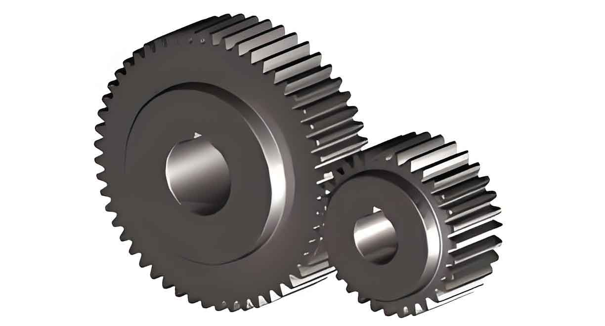
While significant research has been dedicated to understanding the effects of gear faults like pitting, cracking, and wear on TVMS and dynamics, the influence of assembly-level errors, particularly center distance deviation, warrants deeper exploration. Center distance deviation refers to the discrepancy between the actual distance separating the gear axes and its theoretical design value. This deviation can arise from mounting inaccuracies, bearing wear, or shaft deflection under load. It fundamentally alters the theoretical line of action, affecting the contact pattern, load distribution, and consequently, the effective mesh stiffness of the engaging spur gears. This paper presents a comprehensive investigation into the influence of center distance deviation on the static and dynamic behavior of spur gears. The primary objective is to quantify how such deviations impact the mesh stiffness, static transmission error, and the ensuing dynamic vibration response under various operational conditions, including different rotational speeds and load torques.
Fundamental Principles of Mesh Stiffness and Natural Frequency
Accurately characterizing the mesh stiffness and system natural frequencies is paramount for any dynamic analysis of spur gears. The time-varying nature of the mesh stiffness is a principal source of parametric excitation within the gear system. Simultaneously, the system’s natural frequencies define its inherent response characteristics to these excitations.
Elastic deformation of the gear teeth under load causes a discrepancy between the theoretical and actual angular positions of the gears. This kinematic error, when projected onto the line of action, is termed the transmission error (TE). For the driving gear, this can be expressed as:
$$ \Delta \varepsilon = R_{b1} (\theta_{1a} – \theta_{1b}) $$
where $\Delta \varepsilon$ is the transmission error along the line of action, $R_{b1}$ is the base circle radius of the driving gear, $\theta_{1a}$ is its actual angular displacement, and $\theta_{1b}$ is its theoretical angular displacement.
The mesh stiffness can be considered in either torsional or linear form. For analysis along the line of action, the linear mesh stiffness $K_m$ is more convenient. It relates the normal mesh force to the linear deflection (i.e., the TE). The normal mesh force $F_n$ is derived from the output torque $T$ and the base circle radius of the driven gear $R_{b2}$. Therefore, the linear mesh stiffness at any meshing instant is given by:
$$ K_m = \frac{F_n}{\Delta \varepsilon} = \frac{T / R_{b2}}{R_{b1} (\theta_{1a} – \theta_{1b})} $$
The fundamental natural frequency $f_0$ of the gear pair system, considering only the torsional mode related to mesh compliance, is directly dependent on this mesh stiffness and the equivalent inertia of the system. It can be approximated by:
$$ f_0 = \frac{1}{2\pi} \sqrt{\frac{K_m}{m_e}} $$
Here, $m_e$ represents the equivalent mass of the system, derived from the moments of inertia of the two gears. The equivalent mass $m_e$ is calculated as:
$$ m_e = \frac{I_1 I_2}{I_1 R_{b2}^2 + I_2 R_{b1}^2} $$
where $I_1$ and $I_2$ are the mass moments of inertia of the driving and driven spur gears, respectively. Since $K_m$ varies periodically with the gear rotation, the natural frequency $f_0$ is not a single value but also exhibits a periodic fluctuation. This characteristic is crucial for identifying potential resonance conditions.
Static Analysis: Influence of Center Distance Deviation on Mesh Stiffness and TE
Finite Element Modeling Approach
To isolate and study the effect of center distance deviation on the static mesh characteristics, a series of finite element (FE) models were developed. The analysis focuses on a single tooth pair engagement cycle, which is discretized into 20 distinct contact points, effectively capturing the stiffness variation from the start to the end of a single mesh. Models were created for three different center distance deviations: 0 mm (nominal), 0.06 mm, and 0.12 mm. The geometric parameters of the studied spur gears are summarized in Table 1.
| Parameter | Driving Gear | Driven Gear |
|---|---|---|
| Number of Teeth, $Z$ | 31 | 36 |
| Module, $m_n$ (mm) | 3 | 3 |
| Face Width (mm) | 12 | 12 |
| Pressure Angle, $\alpha$ (°) | 25 | 25 |
| Center Distance, $a$ (mm) – Theoretical | 100.5 | |
A static structural analysis was performed for each of the 60 scenarios (20 mesh points × 3 deviations). In the FE model, rigid body shells were attached to the gear hubs. The driven gear hub was constrained in all degrees of freedom except rotation about its axis, while the driving gear hub was fully constrained. A slowly ramping torque was applied to the driven gear to eliminate initial backlash and achieve a steady-state loaded condition of 200 Nm. Surface-to-surface contact was defined between the engaging tooth flanks. The simulations were solved using an implicit solver to obtain the static deformation and reaction forces.
Results: Mesh Stiffness and Static TE
The static transmission error $\Delta \varepsilon$ was computed from the simulated angular displacement of the driven gear. The results, plotted across the mesh cycle for the three deviations, reveal a clear trend. As the center distance deviation increases, both the magnitude and the fluctuation amplitude of the static TE increase. The deviation alters the ideal contact condition, leading to less favorable load sharing and increased geometric mismatch.
The time-varying mesh stiffness (TVMS) was calculated using the formula for $K_m$. The computed stiffness curves over one mesh period are shown conceptually in the figure below, and key values are summarized in Table 2. The characteristic pattern of higher stiffness in the double-tooth contact region and lower stiffness in the single-tooth contact region is evident.
| Center Distance Deviation (mm) | Avg. Stiffness in Single-Tooth Region (N/mm) | Avg. Stiffness in Double-Tooth Region (N/mm) | Percentage Change in Single-Tooth Stiffness | Percentage Change in Double-Tooth Stiffness |
|---|---|---|---|---|
| 0.00 (Nominal) | 154,886 | 201,578 | 0% (Reference) | 0% (Reference) |
| 0.06 | 141,105 | 171,055 | -8.9% | -15.1% |
| 0.12 | 141,733 | 141,733 | -8.5% | -29.7% |
The analysis leads to two critical observations regarding the performance of spur gears under misalignment:
- Overall Stiffness Reduction: The effective mesh stiffness decreases with increasing center distance deviation. The double-tooth contact region is more sensitive to this deviation than the single-tooth region. For every 0.06 mm increase in deviation, the single-tooth stiffness decreases by approximately 9%, while the double-tooth stiffness decreases by about 15%.
- Altered Mesh Characteristics: The deviation causes the contact points to shift from their theoretical paths. This shift can lead to localized stiffness increases at certain points within the single-tooth engagement phase and degrades the smooth transition between single and double contact, potentially harming mesh stability.
Dynamic Vibration Response Analysis
Building upon the static understanding, a dynamic transient analysis was conducted to investigate the vibrational response of the spur gears under operating conditions. A dynamic FE model was established where both gears were free to rotate. A constant load torque was applied to the driven gear, and a constant rotational speed was applied to the driving gear after the load was fully engaged. The influence of three parameters was studied: center distance deviation, rotational speed, and load torque.
Effect of Center Distance Deviation on Dynamics
Models with deviations of 0, 0.03, 0.06, 0.09, 0.12, and 0.15 mm were analyzed under a constant load (200 Nm) and speed (5000 rpm). The dynamic mesh force, dynamic TE, and their frequency spectra were examined.
Dynamic Mesh Force and TE: The fluctuation amplitude of the dynamic mesh force showed a non-linear relationship with deviation. While introducing a deviation increased force fluctuations compared to the nominal case, the fluctuation magnitude did not increase monotonically; it oscillated within a band after a certain point. This is attributed to the competing effects of reduced mesh stiffness and the changing initial backlash/contact condition. In contrast, the fluctuation of the Dynamic TE increased by roughly 15% for each 0.03 mm increment initially but stabilized after the deviation reached approximately 0.06 mm.
Frequency Domain Analysis: The Fast Fourier Transform (FFT) of the dynamic mesh force revealed the system’s excitation characteristics. The mesh frequency $f_m$ and its harmonics (particularly $2f_m$) were the dominant spectral components. The amplitude at the mesh frequency $f_m$ increased with deviation up to a critical point (~0.06 mm) and then plateaued. Notably, the amplitude at the second harmonic $2f_m$, associated with the entry and exit impacts in a mesh cycle, showed a consistent and significant increase with growing deviation—rising by 5% to 31% across the range studied. This indicates that center distance deviation exacerbates impact events during meshing.
| Primary Effect | Observation | Implication for Spur Gears |
|---|---|---|
| Mesh Force Fluctuation | Non-linear increase, stabilizes after critical deviation (~0.06mm) | Increased dynamic loading, but with a saturation effect. |
| Transmission Error Fluctuation | Initial linear increase, stabilizes after critical deviation | Increased primary vibratory excitation, reaching a steady level. |
| Frequency Spectrum | Growth in 2x mesh frequency ($2f_m$) amplitude | Significantly aggravated meshing-in and meshing-out impacts, reducing stability. |
Effect of Rotational Speed
Using a model with a fixed deviation of 0.06 mm and load of 200 Nm, speeds of 2800 rpm (0.56n), 5000 rpm (n), 7500 rpm (1.5n), and 10000 rpm (2n) were simulated, where n=5000 rpm.
Resonance Condition: A critical consideration is when the mesh frequency coincides with the system’s natural frequency range. Using the formula for natural frequency $f_0$ and the range of $K_m$ from the static analysis (≈19075 to 11747 N/m), the resonance speed range was calculated to be between 2764 and 3523 rpm. The 2800 rpm (0.56n) case lies within this resonance band.
Dynamic Response: As expected, the dynamic mesh force fluctuation increased with speed for the non-resonant cases (n, 1.5n, 2n). However, the system operating at the resonance speed (0.56n) exhibited severe dynamic behavior: large-amplitude, aperiodic force fluctuations, and a tremendous increase in dynamic TE fluctuation. The frequency spectrum at resonance was fundamentally different; the integer multiples of the mesh frequency were no longer dominant. Instead, the highest amplitude occurred at a non-integer harmonic (e.g., 2.7$f_m$), and the vibration appeared random, indicating chaotic response and severe loss of mesh contact.
Effect of Load Torque
With deviation fixed at 0.06 mm and speed at 5000 rpm, simulations were run for torques of 100 Nm (0.5T), 200 Nm (T), 300 Nm (1.5T), and 400 Nm (2T).
Non-linear Vibration Growth: The fluctuation of both dynamic mesh force and TE increased non-linearly with increasing torque. More importantly, the nature of the vibration changed. At lower torques (0.5T, T), the mesh force was periodic, and the spectrum was dominated by $f_m$ and $2f_m$. At higher torques (1.5T, 2T), the periodicity deteriorated, and significant spectral amplitudes appeared at other frequencies, notably 1.6$f_m$ and 3$f_m$.
Excitation of Additional Phenomena: This shift is attributed to the excitation of additional dynamic mechanisms under heavy load. First, increased friction force causes a direction reversal at the pitch point, leading to a “pitch-line impact.” Second, the high loads induce noticeable axial vibration in the gear web (spoke), as captured by acceleration measurements from points on the web face. This coupling between tooth mesh dynamics and structural vibration of the gear body creates a more complex frequency response and degrades meshing performance.
| Parameter | Effect on Vibration | Critical Observations |
|---|---|---|
| Rotational Speed | Vibration amplitude increases with speed. | Resonance causes severe tooth separation, chaotic response, random vibration, and exponentially increased impact. |
| Load Torque | Vibration increases non-linearly with torque. | High torque introduces pitch-line impact and excites web/spoke vibration, leading to complex spectra and poorer mesh stability. |
Conclusion
This investigation systematically analyzed the influence of center distance deviation on the static and dynamic behavior of spur gears, extending the analysis to include the effects of rotational speed and load torque. The primary conclusions are as follows:
- Mesh Stiffness Degradation: Center distance deviation reduces the overall effective mesh stiffness of spur gears, with the double-tooth contact region being disproportionately affected. This reduction in stiffness directly contributes to increased static transmission error.
- Dynamic Impact of Deviation: The presence of center distance deviation amplifies the dynamic vibration of the gear pair. However, this effect exhibits a saturation characteristic; beyond a critical deviation value (approximately 0.06 mm for the studied gear pair), the increase in vibratory response levels off. Crucially, deviation consistently aggravates meshing-in and meshing-out impacts, as evidenced by the growing amplitude at the second mesh harmonic ($2f_m$), thereby reducing mesh stability.
- Resonance Catastrophe: Operating spur gears at a rotational speed that excites the system’s natural frequency range leads to a catastrophic degradation of performance. Severe tooth separation occurs, vibration becomes aperiodic and random, and meshing impacts are magnified manifold. Avoiding this resonance zone is critical for reliable operation.
- High-Load Dynamics: Increasing the load torque non-linearly increases vibration levels. At sufficiently high torques, additional phenomena beyond simple entry/exit impacts are triggered. These include pitch-line impacts due to friction reversal and the excitation of structural vibrations in the gear web, complicating the frequency spectrum and leading to deteriorated meshing performance.
In summary, while spur gears are robust components, their dynamic performance is sensitive to assembly imperfections like center distance deviation and operational parameters. Design and assembly tolerances should account for the stiffness loss and impact amplification caused by such deviations. Furthermore, operational envelopes must be carefully defined to avoid resonant conditions and excessively high loads that induce complex, destabilizing dynamic interactions. This analysis provides a framework for understanding these coupled effects in the design and diagnostic phases of gear system engineering.