
In the realm of mechanical power transmission, the spur gear remains a cornerstone component due to its simplicity, reliability, and efficiency. My research interest has long been captivated by the potential for performance enhancement through geometric optimization of the standard spur gear design. Among the various advanced concepts, the asymmetric involute spur gear, characterized by distinct pressure angles on its drive and coast tooth flanks, presents a compelling avenue for achieving superior load capacity, compactness, and noise reduction compared to its symmetric counterpart. While existing literature has established promising improvements in static strength and basic kinematics for this type of spur gear, a thorough investigation into its dynamic characteristics, particularly its modal properties, remains notably underexplored. Modal parameters—the inherent natural frequencies, damping ratios, and mode shapes—are fundamental to understanding and predicting vibrational response, which is critical for avoiding resonance, ensuring structural integrity, and optimizing dynamic design. This gap in knowledge motivated me to undertake a detailed, first-principles study, leveraging modern computational tools to perform a comprehensive finite element-based modal analysis of asymmetric involute spur gears. The primary objective of this work is to systematically derive the tooth profile, construct parameterized models, perform modal extraction, and analyze how the asymmetric pressure angle distribution influences the fundamental dynamic fingerprints of the spur gear. The findings aim to provide foundational insights and practical guidance for the dynamic design and application of high-performance asymmetric spur gears.
The journey begins with the mathematical definition of the asymmetric tooth profile. For a standard symmetric spur gear, a single base circle generates the involute curve for both flanks. In contrast, an asymmetric spur gear requires two different base circles, leading to two distinct involute curves for the drive side (often designed for higher load) and the coast side. To establish a precise geometric model, I define a Cartesian coordinate system with the gear center O as the origin. The positive y-axis is aligned with the line connecting the center to the tip of a tooth, which is considered the starting point for profile generation. For any point M on the drive-side involute, the parametric equations can be derived from the fundamental geometry of an involute curve. Let \( r_M \) be the radial distance from the gear center to point M, and \( \phi_M \) be the angle between the radius vector \( r_M \) and the y-axis. The coordinates of point M are given by:
$$ x_M = r_M \sin \phi_M $$
$$ y_M = r_M \cos \phi_M $$
However, to express this purely in terms of gear design parameters, we incorporate the pressure angle. Let \( \alpha_d \) be the nominal pressure angle on the drive side, \( \alpha_{id} \) be the pressure angle at any arbitrary point M on the drive-side involute (where \( \alpha_{AO} \leq \alpha_{id} \leq \alpha_{ad} \), with \( \alpha_{AO} \) and \( \alpha_{ad} \) being the pressure angles at the start of active profile and at the addendum circle, respectively), \( m \) be the module, and \( z \) be the number of teeth. Using the involute function \( \text{inv}(\alpha) = \tan \alpha – \alpha \), the complete set of parametric equations for the drive-side flank of the asymmetric spur gear is derived as:
$$
\begin{cases}
x_M = \dfrac{m z \cos \alpha_d}{2 \cos \alpha_{id}} \sin\left( \text{inv}(\alpha_{\Delta d}) – \text{inv}(\alpha_{id}) \right) \\[10pt]
y_M = \dfrac{m z \cos \alpha_d}{2 \cos \alpha_{id}} \cos\left( \text{inv}(\alpha_{\Delta d}) – \text{inv}(\alpha_{id}) \right)
\end{cases}
$$
Here, \( \alpha_{\Delta d} \) is a reference angle related to the tooth thickness specification. Similarly, for any point N on the coast-side flank, defined by the coast-side nominal pressure angle \( \alpha_c \) and a local pressure angle \( \alpha_{ic} \) (where \( \alpha_{BO} \leq \alpha_{ic} \leq \alpha_{ac} \)), the profile equations are:
$$
\begin{cases}
x_N = \dfrac{m z \cos \alpha_c}{2 \cos \alpha_{ic}} \sin\left( \text{inv}(\alpha_{\Delta c}) – \text{inv}(\alpha_{ic}) \right) \\[10pt]
y_N = \dfrac{m z \cos \alpha_c}{2 \cos \alpha_{ic}} \cos\left( \text{inv}(\alpha_{\Delta c}) – \text{inv}(\alpha_{ic}) \right)
\end{cases}
$$
These equations form the analytical backbone for generating the precise tooth geometry of the asymmetric involute spur gear. The asymmetry is fundamentally controlled by the independent selection of \( \alpha_d \) and \( \alpha_c \), which directly influence the curvature and strength distribution across the tooth. This mathematical model was implemented as a parameterized script to enable flexible design exploration.
With the profile equations defined, the next step involved translating this mathematics into a three-dimensional solid model suitable for finite element analysis (FEA). I employed a commercial CAD software (Pro/ENGINEER in the original context, though the principle is generic) to create a fully parameterized model of the spur gear. The key geometric parameters for a baseline design are summarized in the table below. This set of parameters allows for systematic variation, particularly the drive-side (\( \alpha_d \)) and coast-side (\( \alpha_c \)) pressure angles, to study their isolated and combined effects on modal properties.
| Parameter | Symbol | Value | Unit |
|---|---|---|---|
| Module | \( m \) | 2.5 | mm |
| Number of Teeth | \( z \) | 10 | – |
| Drive-side Pressure Angle | \( \alpha_d \) | 35 | ° |
| Coast-side Pressure Angle | \( \alpha_c \) | 25 | ° |
| Addendum Coefficient | \( h_a^* \) | 1.0 | – |
| Dedendum/Clearance Coefficient | \( c^* \) | 0.25 | – |
| Face Width | \( b \) | 8 | mm |
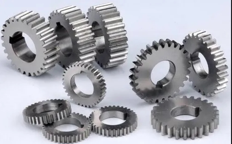
The three-dimensional solid model generated from these parameters serves as the physical representation of the spur gear for all subsequent analyses. To provide a visual reference for the reader regarding the fundamental geometry of a spur gear, an illustrative image is embedded below. This image represents a generic spur gear, highlighting its characteristic straight teeth radiating from a central hub, which is the foundational form upon which the asymmetric involute profile is applied in this study.
The transition from CAD to FEA is a critical step. The solid model was imported into ANSYS, a premier finite element analysis software. The choice of element type significantly impacts the accuracy and computational cost of the modal analysis. For this study, I selected the SOLID186 element. This is a high-order 3D, 20-node hexagonal element that exhibits quadratic displacement behavior, making it well-suited for modeling complex geometries with curved boundaries, such as the involute profile of a spur gear, and for accurately capturing stress and deformation patterns. The material properties were assigned as those of standard structural steel: Young’s Modulus \( E = 210 \) GPa, Poisson’s ratio \( \nu = 0.3 \), and density \( \rho = 7850 \) kg/m³. The meshing process was performed with care, ensuring a sufficiently fine mesh, especially in the critical root fillet and tooth contact regions, to guarantee result fidelity without excessive computational overhead. The resulting finite element model for the baseline asymmetric spur gear comprised several hundred thousand degrees of freedom, forming a robust basis for the eigenvalue extraction to come.
The core of this investigation lies in the modal analysis itself. Modal analysis is the process of determining the inherent vibration characteristics—the natural frequencies and mode shapes—of a structure. In the context of a spur gear, these characteristics dictate how it will respond to dynamic excitations from meshing forces, manufacturing errors, or system vibrations. To extract these modes, I applied the Block Lanczos method within ANSYS. This method is particularly efficient and accurate for large-scale models, as it uses a sequence of Lanczos vectors to approximate the eigenvalues and eigenvectors of the system’s mass and stiffness matrices. The fundamental equation solved in undamped modal analysis is the eigenvalue problem:
$$ ( [K] – \omega_i^2 [M] ) \{\phi_i\} = \{0\} $$
where \( [K] \) is the global stiffness matrix, \( [M] \) is the global mass matrix, \( \omega_i \) is the \( i \)-th natural frequency (in rad/s), and \( \{\phi_i\} \) is the corresponding mode shape vector (eigenvector). The analysis was configured to extract the first 15 modes within a frequency range of 0 to 100 kHz, though the most dynamically significant lower-order modes are the primary focus. The boundary condition applied was a free-free condition, meaning the spur gear was unconstrained. This condition is standard for extracting the intrinsic modal properties of a component before it is integrated into an assembly, as it isolates the gear’s own characteristics from support stiffness effects.
For the baseline asymmetric spur gear model with \( (\alpha_d, \alpha_c) = (35°, 25°) \), the first 10 natural frequencies and their corresponding maximum nodal deformation magnitudes (a measure of the intensity of each mode shape) were computed and are listed in the following table. These results establish a reference point for comparative analysis.
| Mode Order (i) | Natural Frequency, \( f_i \) (Hz) | Maximum Deformation, \( U_{max, i} \) (mm) |
|---|---|---|
| 1 | 93.34 | 3.13 × 10⁻⁴ |
| 2 | 94.73 | 3.08 × 10⁻⁴ |
| 3 | 97.44 | 3.22 × 10⁻⁴ |
| 4 | 98.21 | 4.51 × 10⁻⁴ |
| 5 | 99.77 | 4.72 × 10⁻⁴ |
| 6 | 108.37 | 3.98 × 10⁻⁴ |
| 7 | 111.44 | 3.32 × 10⁻⁴ |
| 8 | 111.58 | 3.92 × 10⁻⁴ |
| 9 | 116.36 | 4.43 × 10⁻⁴ |
| 10 | 123.24 | 4.07 × 10⁻⁴ |
The mode shapes themselves are visual representations of how the spur gear deforms at each natural frequency. The lower-order modes (1 through 6) typically involve global bending, torsional, and axial deformations of the gear body and rim. Higher-order modes (7 and above) begin to exhibit more localized deformation patterns, involving complex combinations of web bending and individual tooth deflection. For instance, the first mode often corresponds to a general “breathing” or radial expansion mode, while the second and third might be orthogonal bending modes. The specific sequence is highly dependent on the gear’s geometry, including its web design, which was kept simple (a solid disc) for this parametric study.
To investigate the influence of asymmetric pressure angles, I conducted a series of parametric studies. Multiple spur gear models were created and analyzed by systematically varying \( \alpha_d \) and \( \alpha_c \). One key study held the coast-side pressure angle constant at \( \alpha_c = 25° \) while varying the drive-side pressure angle \( \alpha_d \) from 20° to 40°. The natural frequencies for the first 10 modes across this range were plotted. The results revealed a crucial insight: the progression of natural frequencies across the modal orders for a spur gear made of the same material and with the same basic macro-geometry (module, teeth number, face width) follows an identical trend, irrespective of the specific pressure angle values on either flank. In other words, the curves of frequency versus mode order for different \( \alpha_d \) values (with fixed \( \alpha_c \)) were nearly superimposed. This indicates that the global stiffness and mass distribution, which primarily govern the lower-order global modes, are not sensitively altered by changes in the pressure angle within this range for this specific spur gear configuration. This finding simplifies the dynamic design process for such a spur gear, as the fundamental resonant frequencies can be considered stable with respect to pressure angle tuning for strength or contact ratio optimization.
A second, more revealing parametric study examined the relationship between the natural frequencies and the sum of the pressure angles, \( \Sigma \alpha = \alpha_d + \alpha_c \). Various pairs \( (\alpha_d, \alpha_c) \) were selected such that their sum ranged from 40° to 65°, covering both symmetric (e.g., 20°/20°, 25°/25°) and asymmetric (e.g., 35°/25°, 40°/20°) configurations for the spur gear. The natural frequencies for modes 1, 4, 7, and 10 were extracted and plotted against \( \Sigma \alpha \). The resulting data unveiled a consistent, non-monotonic relationship across all observed modes:
- For \( 40° \leq \Sigma \alpha \leq 50° \): The natural frequencies exhibited a slow, gradual increase as \( \Sigma \alpha \) increased.
- For \( 50° \leq \Sigma \alpha \leq 60° \): The natural frequencies entered a plateau region, remaining remarkably stable despite changes in the pressure angle sum.
- For \( 60° \leq \Sigma \alpha \leq 65° \): A slow, gradual decrease in natural frequencies was observed.
This “increase-stable-decrease” pattern can be explained by the competing effects of pressure angle on tooth geometry. A higher pressure angle generally leads to a broader tooth base (increasing the area moment of inertia and local stiffness at the root) but also reduces the contact ratio and can alter the effective rim stiffness. The sum of the angles acts as a proxy for the overall “spread” of the involute profiles. Initially, increasing the sum strengthens the tooth globally. Beyond a point (around 50°-60° for this gear), the geometric benefits plateau. Further increase might lead to a more pointed tooth tip or other subtle changes in mass distribution that slightly reduce the overall stiffness-to-mass ratio, hence lowering the natural frequencies. This relationship provides a valuable guideline for designers: selecting a pressure angle sum within the stable plateau region (50°-60°) can offer robustness against minor design variations in the dynamic performance of the spur gear.
Beyond natural frequencies, the modal deformation magnitude is another critical dynamic descriptor. I analyzed how the maximum deformation \( U_{max} \) associated with each mode order behaves. Plotting \( U_{max} \) against mode order \( i \) for various asymmetric and symmetric spur gear configurations yielded a fascinating observation. The envelope of maximum deformation values does not diverge wildly with changes in \( \alpha_d \) or \( \alpha_c \). Instead, as the mode order increases, the values for \( U_{max} \) from all different pressure angle configurations converge towards a common, narrow range. Furthermore, the progression of \( U_{max} \) with increasing mode order resembles a damped sinusoidal oscillation. It exhibits peaks and troughs but with a general trend of decay in the oscillation amplitude, eventually settling into a stable band. Mathematically, this can be loosely likened to a response of the form:
$$ U_{max}(i) \approx A e^{-\zeta i} \sin(2\pi f_m i + \theta) + C $$
where \( A \) is an initial amplitude, \( \zeta \) is a damping coefficient related to the modal density and energy distribution among modes, \( f_m \) is a modulation frequency, \( \theta \) is a phase, and \( C \) is a constant asymptotic value. The key finding is that the effective “damping coefficient” \( \zeta \) appears largely independent of the specific asymmetric pressure angle分配 (distribution). Whether the spur gear is symmetric (e.g., 25°/25°) or highly asymmetric (e.g., 40°/20°), the rate at which the deformation magnitudes converge is similar. This implies that the overall modal energy distribution and the relative participation of different mode shapes are intrinsic properties of the spur gear’s macro-form (disc diameter, face width, number of teeth) and material, rather than being strongly modulated by the specific involute flank asymmetry. This is a significant result for noise and vibration specialists, suggesting that while asymmetry can greatly improve bending strength, it may not drastically alter the fundamental modal damping characteristics of the gear body itself; other design features like web patterning or damping treatments would be more effective for that purpose.
The findings from this extensive modal analysis lead to several important conclusions and design implications for the asymmetric involute spur gear. First and foremost, the fundamental natural frequency spectrum of a spur gear, constructed from a given material and with fixed core dimensions (module, tooth count, face width), demonstrates remarkable stability with respect to variations in the individual drive-side or coast-side pressure angles. This decouples the primary dynamic tuning (avoidance of critical speeds) from the detailed tooth flank optimization for load capacity or efficiency. Designers can select \( \alpha_d \) and \( \alpha_c \) based on static or kinematic performance targets without inadvertently shifting the gear’s key resonant frequencies into a problematic excitation range.
Second, a more nuanced relationship exists between the natural frequencies and the sum of the pressure angles \( (\Sigma \alpha) \). The identified pattern—gradual increase, followed by a stability plateau, and then a gradual decrease—offers a clear optimization window. For the spur gear parameters studied, aiming for a \( \Sigma \alpha \) between 50° and 60° appears to yield natural frequencies that are both relatively high (desirable for stiffness) and insensitive to manufacturing tolerances or small design changes in the pressure angles. This provides a valuable rule of thumb during the preliminary design phase of an asymmetric spur gear.
Third, the behavior of the modal deformation magnitudes reveals a self-regulating dynamic characteristic. Regardless of the asymmetry introduced in the tooth profile, the maximum deformations across successive modes tend to oscillate and dampen, converging to a similar asymptotic level. This suggests that the potential for extreme vibratory amplitudes in higher modes is not exacerbated by the asymmetry itself. The vibrational energy, in a sense, is distributed across the modes in a predictable manner that is primarily governed by the overall gear blank geometry. Therefore, concerns about asymmetric spur gears inducing unexpected high-amplitude, high-frequency vibrations appear unfounded based on this modal analysis.
In summary, this work has systematically bridged the gap between the geometric definition and the dynamic characterization of the asymmetric involute spur gear. By deriving the precise profile equations, building parameterized finite element models, and executing a detailed modal analysis, I have mapped out how the key dynamic properties—natural frequencies and modal deformations—respond to changes in the defining pressure angles. The results affirm that the asymmetric spur gear retains stable and predictable dynamic fundamentals, making it a reliable candidate for high-performance applications where its static advantages in strength and compactness are paramount. Future work could extend this analysis to consider the effects of mesh stiffness variation, damping from lubricated contacts, and the dynamic response of a full gear pair under load, further enriching the understanding of this innovative spur gear technology. The journey from a mathematical curve to a dynamically characterized component underscores the power of integrated computer-aided engineering in advancing mechanical design.