
In the mechanical industry, gears are among the most widely used components, playing a critical role in power transmission and motion control across various applications. The precise three-dimensional modeling of spur gear teeth is fundamental for advanced engineering processes such as dynamic simulation, NC machining, interference checking, and finite element analysis. Traditional CAD approaches often approximate the gear tooth profile by calculating discrete points along the contour and fitting a spline curve, which can lead to inaccuracies due to the non-standard nature of the involute curve. This article, based on my professional experience, details a method for achieving accurate parametric design and three-dimensional modeling of spur gears using the expression functionality in UGNX3.0 software. By directly employing the involute equation, this approach enables the generation of exact tooth profiles, facilitating a fully parameterized model where modifications to key parameters automatically update the entire geometry. This parametric capability is essential for optimizing spur gear performance, reducing development cycles, and lowering production costs.
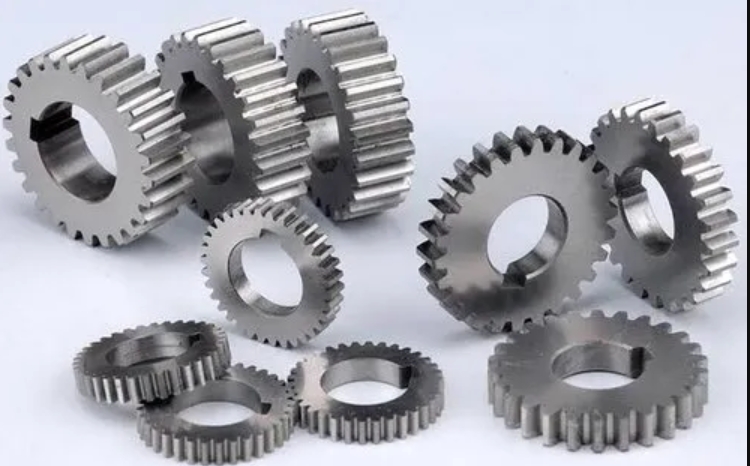
The structure of a standard spur gear consists of several key elements: the teeth, tooth spaces, addendum circle, dedendum circle, base circle, and pitch circle. Each of these elements is governed by a specific set of parameters. For an involute spur gear, the primary parameters that define its shape and dimensions include the module, number of teeth, pressure angle, addendum coefficient, dedendum coefficient, profile shift coefficient, and face width. To meet various technical requirements and design specifications, it is crucial to consider how changes in these parameters affect the spur gear’s geometry. These parameters are interrelated through a series of mathematical expressions, forming the basis for parametric design. By extracting these parameters and defining them as variables within the CAD environment, a parametric model of the spur gear can be created. Assigning a new set of parameter values instantly generates a different spur gear, demonstrating the power of parametric modeling. While creating accurate three-dimensional models of involute spur gears can be challenging in lower-end CAD software due to the complex tooth profile, UGNX3.0’s robust parametric design tools, combined with the involute equation, allow for the precise definition of the tooth flank curve and the establishment of related expressions. This ensures all model dimensions and feature parameters are interconnected, leading to an accurate three-dimensional model of the involute spur gear.
The foundational step in parametric modeling is identifying and defining the master parameters. For a modified involute spur gear, the following parameters are critical. The table below summarizes these key parameters for a spur gear:
| Parameter Symbol | Description | Typical Role in Spur Gear Design |
|---|---|---|
| m | Module | Defines the size scale of the spur gear teeth; a fundamental parameter for metric gears. |
| Z | Number of Teeth | Determines the gear ratio and the physical size of the spur gear. |
| α | Pressure Angle (at Pitch Circle) | Affects the tooth strength, contact ratio, and backlash of the spur gear mesh. |
| ha* | Addendum Coefficient | Defines the height of the tooth above the pitch circle relative to the module. |
| c* | Dedendum Coefficient | Defines the depth of the tooth space below the pitch circle, ensuring clearance. |
| x | Profile Shift Coefficient (Modification) | Alters the tooth thickness and profile to avoid undercutting, improve strength, or adjust center distance for a spur gear pair. |
| b | Face Width | The axial length of the spur gear teeth, influencing load capacity. |
While standard spur gears, where ha*, c*, and α are standard values and x=0, offer advantages like design simplicity and interchangeability, they have limitations in high-speed or heavy-duty applications. The profile shift modification, or “correction,” is widely adopted to overcome these issues. In a modified spur gear, the profile shift coefficient x is introduced. This modification does not alter the size of the base circle or the pitch circle, and the fundamental involute equation remains the same as for a standard spur gear. However, it changes the tooth thickness, tooth height, addendum circle diameter, and dedendum circle diameter. The relevant formulas for a modified spur gear are as follows:
The pitch circle radius is given by:
$$ r = \frac{m \cdot Z}{2} $$
The base circle radius, which governs the involute shape, is:
$$ r_b = r \cdot \cos(\alpha) $$
The tooth thickness on the pitch circle for a modified spur gear is:
$$ s = \frac{\pi m}{2} + 2 x m \tan(\alpha) $$
The dedendum circle radius for the modified spur gear is:
$$ r_f = r – h_f = r – (h_a^* + c^* – x)m $$
The addendum circle radius for the modified spur gear is:
$$ r_a = r + h_a = r + (h_a^* + x)m $$
Additionally, a fillet radius at the root of the spur gear tooth is often required to reduce stress concentration. A common formula for this root fillet radius is:
$$ r_p = \frac{c^* m}{1 – \sin(\alpha)} $$
These equations form the mathematical backbone for the parametric model of the modified spur gear. Implementing them within UG’s expression editor is the next critical step.
UGNX3.0 provides a powerful expression editor that allows users to define variables and mathematical relationships. Since Greek letters cannot be directly input, parameters are represented using English equivalents (e.g., ‘alfa’ for α). The following table lists the essential expressions needed to define a modified spur gear model. These expressions create a fully associative system where changing a master parameter like module (m) or number of teeth (Z) automatically updates all dependent geometry for the spur gear.
| Expression Name | UG-Compatible Formula | Mathematical Equivalent & Purpose |
|---|---|---|
| t | t = 0 | Parameter for curve generation, varies from 0 to 1. |
| afa | afa = 180 * t | Roll angle (in degrees) for the involute, ranges from 0° to 180°. |
| m | m = 4 | Module (example value, a key driver for spur gear size). |
| z | z = 30 | Number of teeth (defines the count on the spur gear). |
| alfa | alfa = 20 | Pressure angle in degrees (standard value for many spur gears). |
| ha_star | ha = 1 | Addendum coefficient (standard value). |
| c_star | c = 0.25 | Dedendum coefficient (standard value). |
| x | x = 0.05 | Profile shift coefficient (positive for this modified spur gear). |
| b | b = 20 | Face width of the spur gear. |
| r | r = m * z / 2 | Pitch circle radius: $$ r = \frac{m Z}{2} $$ |
| rb | rb = r * cos(alfa) | Base circle radius: $$ r_b = r \cos(\alpha) $$ |
| u | u = afa * pi() / 180 | Roll angle in radians: $$ u = \theta $$ (for involute equation). |
| xt | xt = rb * sin(afa) – rb * u * cos(afa) | X-coordinate of involute: $$ x = r_b (\sin u – u \cos u) $$ |
| yt | yt = rb * cos(afa) + rb * u * sin(afa) | Y-coordinate of involute: $$ y = r_b (\cos u + u \sin u) $$ |
| rf | rf = r – (ha + c – x) * m | Dedendum circle radius: $$ r_f = r – (h_a^* + c^* – x)m $$ |
| ra | ra = r + (ha + x) * m | Addendum circle radius: $$ r_a = r + (h_a^* + x)m $$ |
| rp | rp = c * m / (1 – sin(alfa)) | Root fillet radius: $$ r_p = \frac{c^* m}{1 – \sin \alpha} $$ |
| sat | sat = (tan(alfa) – alfa*pi()/180)*180/pi() + (1/z + 4*x*tan(alfa)/(pi()*z))*90 | Angle to mirror center for one spur gear tooth space. |
The derivation of the ‘sat’ expression is crucial for correctly positioning the involute curves to form a single tooth space on the spur gear. The involute curve generated by the parametric equations starts at a point on the base circle along the Y-axis. To create a symmetrical tooth profile, this curve must be mirrored. The mirror line is offset from the Y-axis by an angle θ. This angle is the sum of the involute roll angle at the pitch circle (θk) and half of the angular tooth thickness on the pitch circle (θ’). For a standard spur gear, θ’ would be π/Z. For our modified spur gear, the angular tooth thickness on the pitch circle is s/r. Therefore:
$$ \theta’ = \frac{s}{2r} = \frac{s}{mZ} $$
Substituting the expression for s:
$$ \theta’ = \frac{\pi m/2 + 2 x m \tan \alpha}{mZ} = \frac{\pi}{2Z} + \frac{2x \tan \alpha}{Z} $$
The roll angle at the pitch circle pressure angle α is:
$$ \theta_k = \tan \alpha – \alpha \text{ (in radians)} $$
Thus, the total angle θ in degrees is:
$$ \theta = (\tan \alpha – \alpha) \cdot \frac{180}{\pi} + \left( \frac{\pi}{2Z} + \frac{2x \tan \alpha}{Z} \right) \cdot \frac{180}{\pi} $$
This simplifies to the expression used in the table:
$$ \theta = (\tan(\alpha) – \alpha \cdot \pi/180) \cdot 180/\pi + (1/Z + 4x \tan(\alpha)/(\pi Z)) \cdot 90 $$
This precise calculation ensures the accurate formation of the tooth space for the parametric spur gear model.
With all expressions defined, the step-by-step parametric design process for creating the modified spur gear in UG can be executed. The following sequence details the procedure, leveraging the associative expressions at every stage to maintain full parametric control over the spur gear geometry.
- Input Expressions: Open the expression editor in UG and input all the formulas listed in the table above. This establishes the parameter set that will drive the entire spur gear model.
- Generate Involute Curve: Navigate to the Curve menu and select the Law Curve command. In the dialog box, choose By Equation. Define the system parameter ‘t’ as the variable. Set the X-law to the expression ‘xt’, the Y-law to ‘yt’, and the Z-law as a constant 0. This action generates the precise involute curve in the XY-plane, which represents one flank of a single spur gear tooth.
- Rotate Work Coordinate System (WCS): To create the mirror line, the WCS must be rotated. Use the Rotate WCS function. Select the option to rotate around the negative Z-axis (from Y-axis towards X-axis). In the angle field, input the expression ‘sat’. This rotates the WCS so that its Y-axis now lies along the desired mirror line for the tooth space of the spur gear.
- Mirror the Involute Curve: Using the rotated WCS Y-axis as the mirror line, create a mirrored copy of the initial involute curve. This results in two symmetric involute curves that define the flanks of a single tooth space on the spur gear.
- Draw Circles: With the origin (0,0,0) as the center, draw two circles. The first circle’s radius should be defined by the expression ‘rf’ (dedendum circle). The second circle’s radius should be defined by ‘ra’ (addendum circle). These circles bound the active profile of the spur gear teeth.
- Create Root Fillet: Apply a fillet (blend) between the lower ends of the involute curves and the dedendum circle (‘rf’). The radius for this fillet should be defined by the expression ‘rp’. This step is vital for reducing stress concentration at the root of the spur gear tooth.
- Trim Curves: Use the trim function to create a closed, continuous profile. Trim the involute curves, the addendum circle (‘ra’), and the dedendum circle (‘rf’) at their intersection points to form a single, closed loop representing the cross-sectional shape of one tooth space.
- Create Gear Blank: Extrude the dedendum circle (‘rf’) along the Z-axis for a distance defined by the face width expression ‘b’. This creates the cylindrical body of the spur gear blank.
- Extrude Tooth Space: Use the extruded feature on the closed tooth space profile created in step 7. Set the extrusion start to 0 and the end to ‘b’. In the Boolean operation, select Unite to merge this extrusion with the gear blank created in step 8. This actually creates a solid by adding material where the teeth are, but note: the profile is for the space between teeth. To correctly model the spur gear, one should extrude the tooth profile (the area between the two involutes from the addendum to the filleted root). In practice, it’s often easier to extrude the tooth space profile as a Subtract operation to cut the space from the blank, or extrude the tooth profile itself as an Unite. The described method likely extrudes the closed loop (which is the air space) using Unite, which would create a solid spanning from one tooth flank to the next, effectively forming one tooth. Let’s clarify: The closed loop bounded by the two involutes, the addendum arc, and the root fillet/dedendum arc represents the area of a single tooth. Extruding this with Unite adds a single tooth to the gear blank. This is a critical step in building the spur gear model.
- Circular Pattern: With a single tooth solid created, use the circular pattern (instance) feature. The number of instances is defined by the expression ‘z’ (number of teeth). The rotation angle is 360/z degrees. The pattern axis is the Z-axis through the origin. This operation replicates the single tooth around the entire circumference, completing the full set of teeth for the spur gear.
- Add Central Features: Finally, create the central bore and keyway on the spur gear model using standard sketch and extrude/subtract commands. These features can also be parameterized by linking their dimensions to expressions based on the master gear parameters (e.g., bore diameter could be a function of the pitch diameter).
The entire process, from expression definition to final solid model, is highly associative. Any change to a master parameter, such as increasing the module ‘m’ or adjusting the profile shift coefficient ‘x’, automatically updates all related expressions, curves, and solid features, resulting in a new, accurate spur gear model in moments. This parametric workflow is immensely powerful for designing families of spur gears or optimizing a specific spur gear design through iterative analysis.
To further illustrate the relationships and provide a quick reference for spur gear designers, the following table consolidates the core geometric calculations for both standard and modified spur gears. This highlights the impact of the profile shift coefficient ‘x’ on the final spur gear dimensions.
| Geometric Element | Standard Spur Gear (x=0) | Modified Spur Gear (x ≠ 0) |
|---|---|---|
| Pitch Diameter (d) | $$ d = m Z $$ | $$ d = m Z $$ (unchanged) |
| Base Diameter (db) | $$ d_b = d \cos \alpha $$ | $$ d_b = d \cos \alpha $$ (unchanged) |
| Addendum (ha) | $$ h_a = h_a^* m $$ | $$ h_a = (h_a^* + x) m $$ |
| Dedendum (hf) | $$ h_f = (h_a^* + c^*) m $$ | $$ h_f = (h_a^* + c^* – x) m $$ |
| Addendum Circle Diameter (da) | $$ d_a = d + 2h_a^* m $$ | $$ d_a = d + 2(h_a^* + x) m $$ |
| Dedendum Circle Diameter (df) | $$ d_f = d – 2(h_a^* + c^*) m $$ | $$ d_f = d – 2(h_a^* + c^* – x) m $$ |
| Tooth Thickness on Pitch Circle (s) | $$ s = \frac{\pi m}{2} $$ | $$ s = \frac{\pi m}{2} + 2 x m \tan \alpha $$ |
In conclusion, UG is an exceptionally powerful tool for parametric design. By leveraging its associative capabilities and expression functionality, engineers can efficiently implement parametric design for complex components like spur gears. The method described, which uses the fundamental involute equation to precisely define the tooth profile, ensures accuracy that surpasses approximation-based methods. This parametric approach for spur gears enables rapid design iterations, easy generation of gear families from a single template, and seamless integration with downstream applications such as simulation and manufacturing. Ultimately, adopting such a parametric modeling strategy for spur gears contributes significantly to shortening product development cycles, reducing production costs, and optimizing the performance and reliability of mechanical systems.