
Gear transmission stands as one of the most critical and widely utilized forms of mechanical power transmission, finding extensive applications across industries such as automotive, maritime, aerospace, and wind power. A spur gear system is fundamentally an elastic system. When loaded, the gear teeth deform, introducing excitations at the points of mesh-in and mesh-out during the engagement process. To mitigate these excitations, tooth profile modification is often employed. Substantial theoretical and experimental evidence confirms that tooth profile modification is an effective measure for reducing gear vibration, meshing impact, and transmission error.
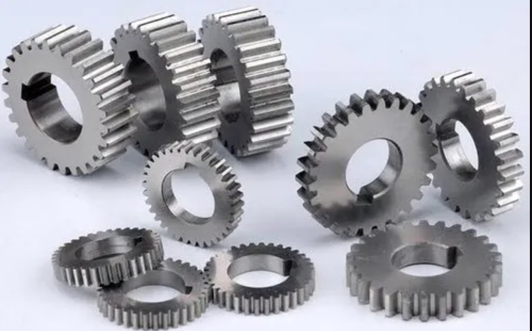
In this study, I investigate the dynamic behavior of a spur gear pair under different tooth profile modification schemes. The core of the analysis involves calculating key parameters such as time-varying mesh stiffness and static transmission error for various modification amounts. Subsequently, I establish a dynamic model for a single-stage spur gear pair to analyze its dynamic response characteristics. My findings reveal that a variable-increment approximation method is highly effective for determining the contact point positions during the meshing process of non-standard, modified involute spur gears. Furthermore, the frequency spectrum of the dynamic transmission error contains both harmonic components from the stiffness excitation and the system’s natural frequency components. A critical condition to be rigorously avoided occurs when these frequencies coincide, leading to a progressive, unbounded increase in the vibration amplitude of the dynamic transmission error over time.
Determining the Meshing Point Position for Modified Tooth Pairs
Form of Tooth Profile Modification
When applying tip relief to a spur gear, two key parameters must be defined: 1) the start position of the relief, and 2) the amount of relief at the tooth tip. In my analysis, I adopt an early modification method. The modification is applied from the start of the single-tooth contact region, denoted as point C, which is also the transition point from double-tooth to single-tooth contact. The modified profile segment CD is constructed using another involute curve with a pressure angle larger than that of the standard gear involute. This is achieved by defining a modified base circle radius $r’_b$, where $r_b$ is the base circle radius of the original involute. Different values of $r’_b$ correspond to different amounts of tip relief $C_a$.
Calculation Example and Modification Parameters
My analysis focuses on a specific single-stage spur gear pair. The input parameters for this spur gear system are detailed in Table 1.
| Parameter | Pinion | Gear |
|---|---|---|
| Number of Teeth | 34 | 36 |
| Face Width (mm) | 510 | 500 |
| Normal Module $m_n$ (mm) | 20 | |
| Normal Pressure Angle $\alpha_n$ (°) | 20 | |
| Normal Addendum Modification Coefficient | 0.2706 | 0.2551 |
| Young’s Modulus $E$ (GPa) | 206 | |
| Poisson’s Ratio $\nu$ | 0.275 | |
| Density $\rho$ (kg/m³) | 9700 | |
I examine four distinct modification cases, labeled A through D, with the control parameter being the difference between the original and modified base circle radii, $r_b – r’_b$. The corresponding tip relief amounts $C_{a1}$ for the pinion and $C_{a2}$ for the gear are calculated and presented in Table 2.
| Case | $r_b – r’_b$ (mm) | $C_{a1}$ (μm) | $C_{a2}$ (μm) |
|---|---|---|---|
| A (Unmodified) | 0 | 0 | 0 |
| B | 0.1 | 9.48 | 10.35 |
| C | 0.2 | 18.95 | 20.66 |
| D | 0.5 | 47.28 | 51.56 |
Calculation of the Meshing Point for Modified Teeth
For standard involute spur gears, analytical formulas can precisely determine the contact point during meshing. However, after profile modification, the tooth profile is no longer a standard involute, rendering traditional analytical methods less accurate. To address this challenge, I developed and implemented a variable-increment successive approximation algorithm within MATLAB to accurately locate the meshing point for modified spur gear pairs.
The core principle of this algorithm is illustrated in Figure 1. For each incremental rotation angle of the pinion profile, the gear profile is rotated towards it with an initial, relatively large step angle. When an intersection between the two profiles is detected, the rotation direction is reversed, and the step angle is reduced to one-tenth of its previous value for the next approximation step. This process—reversing direction and reducing the step size by a factor of ten each time an intersection is detected or lost—is iterated until the step angle meets a predefined precision tolerance. The final intersection point, A, is identified as the precise meshing point. This method ensures rapid convergence due to the exponential decay of the step size, and the accuracy of the contact point location can be controlled to any desired level by setting the number of iterations and the initial step size.
To visualize the impact of modification on the meshing process, I applied a significant modification amount ($r_b – r’_b = 20$ mm) to the spur gear pair. Figure 2 displays the calculated positions of successive meshing points and the resulting path of contact for the modified profiles. The path of contact is no longer a single straight line but a composite path A–F, consisting of straight segments (AB, CD, EF) and curved/transition segments (BC, DE). Figures 3 and 4 compare the original and modified profiles for the pinion and gear, respectively, clearly showing the modified segment starting from the calculated point C.
Dynamic Response Analysis of the Spur Gear Pair Under Different Modification Amounts
Establishing the Dynamic Model for a Single-Stage Spur Gear Pair
I adopt a lumped-parameter dynamic model for the spur gear pair, neglecting the effects of backlash. The model is depicted in Figure 5. In this model, PQ represents the theoretical line of action. The parameters $R_i$, $I_i$, $\theta_i$, and $T_i$ (where $i = 1, 2$) denote the base circle radius, mass moment of inertia, torsional vibration displacement, and applied torque for the pinion (i=1) and gear (i=2), respectively. The terms $k(t)$, $c$, and $e(t)$ represent the time-varying mesh stiffness, damping, and static transmission error of the spur gear pair.
The equations of motion are derived as follows:
$$
I_1 \ddot{\theta}_1 + c R_1 (R_1 \dot{\theta}_1 – R_2 \dot{\theta}_2) + R_1 k(t) (R_1\theta_1 – R_2\theta_2 – e(t)) = T_1
$$
$$
I_2 \ddot{\theta}_2 – c R_2 (R_1 \dot{\theta}_1 – R_2 \dot{\theta}_2) – R_2 k(t) (R_1\theta_1 – R_2\theta_2 – e(t)) = -T_2
$$
These equations can be condensed into a single-degree-of-freedom system by transforming the torsional displacements into an equivalent displacement along the line of action. Defining the Dynamic Transmission Error (DTE) as $x = R_1\theta_1 – R_2\theta_2$, we obtain $\dot{x} = R_1 \dot{\theta}_1 – R_2 \dot{\theta}_2$ and $\ddot{x} = R_1 \ddot{\theta}_1 – R_2 \ddot{\theta}_2$. The combined dynamic equation becomes:
$$
\ddot{x} + \frac{c}{m_e} \dot{x} + \frac{k(t)}{m_e} x = F_m + \frac{e(t) k(t)}{m_e}
$$
where the equivalent mass $m_e$ and the mean force $F_m$ are given by:
$$
m_e = \frac{I_1 I_2}{I_1 R_2^2 + I_2 R_1^2}, \quad F_m = \frac{R_1 T_1}{I_1} + \frac{R_2 T_2}{I_2}
$$
This formulation is central to analyzing the dynamic response of the spur gear transmission system.
Calculation of Time-Varying Mesh Stiffness and Static Transmission Error
For the spur gear pair defined in Table 1, I calculate the time-varying mesh stiffness over one complete meshing cycle using the potential energy method based on the mechanics of materials, treating the tooth as a non-uniform cantilever beam. The resulting mesh stiffness variation for one mesh period is shown in Figure 6. The periodic fluctuation is a fundamental source of parametric excitation in spur gear dynamics.
The Static Transmission Error (STE) is defined as the deviation of the actual position of the driven gear from its theoretical position, measured along the line of action. It primarily comprises manufacturing and assembly errors, as well as errors induced by load-dependent tooth deflections. Assuming all contact occurs on the theoretical line of action, introducing profile modification inherently creates a No-Load Transmission Error (NLTE). In this study, I focus on the Loaded Deformation Error (DE) and the NLTE introduced by modification. The total Transmission Error (TE) for a spur gear pair is expressed as:
$$
\text{TE} = \text{DE}_1 + \text{DE}_2 + \text{NLTE}
$$
where $\text{DE}_1$ and $\text{DE}_2$ are the deformation errors for the pinion and gear, respectively. The NLTE is calculated for each pinion rotation increment as the difference between the contact point positions on the unmodified and modified profiles, using the variable-increment algorithm. The deformation error (DE) for each contact point is computed using the cantilever beam model. The calculated total transmission error (TE) for a single tooth pair over its engagement period, for the four modification cases, is presented in Figure 7.
Analysis of Dynamic Response Characteristics
Substituting the calculated parameters—time-varying mesh stiffness $k(t)$, static transmission error $e(t)$, and other system constants—into the dynamic equation, I solve the differential equation numerically using the Runge-Kutta method to obtain the dynamic transmission error $x(t)$ response. The input torque is set to $T_1 = 5000$ N·m, and the load torque is $T_2 = T_1 \cdot (R_2 / R_1)$ to maintain system equilibrium.
Figure 8 shows the dynamic transmission error response for modification Case D with a pinion rotational speed of $n_1 = 7.2$ r/s. Performing a Fast Fourier Transform (FFT) on this response yields its frequency spectrum, shown in Figure 9. Similarly, the FFT of the time-varying mesh stiffness for this condition reveals its harmonic content, as shown in Figure 10. To quantify the effects, Table 3 lists the amplitude of the first harmonic component of the Static Transmission Error (STE) for all four cases at $n_1 = 7.2$ r/s, while Table 4 lists the amplitude of the fourth harmonic component of the Dynamic Transmission Error (DTE).
| Modification Case | STE First Harmonic Amplitude (mm) |
|---|---|
| A | $3.477 \times 10^{-6}$ |
| B | $2.379 \times 10^{-2}$ |
| C | $4.769 \times 10^{-2}$ |
| D | $1.192 \times 10^{-1}$ |
| Modification Case | DTE Fourth Harmonic Amplitude (mm) |
|---|---|
| A | $1.381 \times 10^{-5}$ |
| B | $5.472 \times 10^{-2}$ |
| C | $1.137 \times 10^{-1}$ |
| D | $2.861 \times 10^{-1}$ |
From Tables 3 and 4, a clear trend is observed for this specific spur gear system: as the amount of tooth profile modification increases, both the static and dynamic transmission errors increase. This indicates that excessive modification can be detrimental to the quietness and smoothness of the spur gear transmission, contrary to its intended purpose.
Examining Figure 9, the frequency spectrum of the DTE contains harmonic components from the stiffness excitation and other distinct frequency components related to the system’s inherent dynamics. While Figure 10 shows the first harmonic of the mesh stiffness excitation is the strongest ($f_1 = 230.4$ Hz for $n_1=7.2$ r/s), Figure 9 reveals that the fourth harmonic ($f_2 = 4 \times f_1 = 921.6$ Hz) has a more pronounced effect on the DTE amplitude in this case. Furthermore, the spectrum shows additional harmonic families (e.g., ~239.4 Hz, 505.1 Hz, 735.8 Hz, 966.2 Hz, 1197 Hz, 1427 Hz). These resemble the system’s modal frequencies but shift with rotational speed.
A critical phenomenon occurs when one of these system frequency components coincides with a major harmonic of the mesh stiffness excitation. This resonance leads to a progressive, unbounded growth in the vibration amplitude. This is demonstrated in Figure 11, which shows the DTE response for modification Case D at a lower pinion speed of $n_1 = 6.0$ r/s. The amplitude clearly increases over time. The corresponding frequency spectra (Figures 12 and 13) confirm that at this speed, a harmonic of the mesh stiffness (the fourth harmonic, $f=768$ Hz) coincides with one of the system’s natural frequencies (~768 Hz), triggering the unstable response. This condition must be strictly avoided in the design and operation of spur gear systems.
Conclusions
Through the numerical analysis of a spur gear transmission system considering tooth profile modification, I have arrived at several key conclusions. First, the variable-increment successive approximation algorithm implemented in MATLAB proved to be a robust and accurate method for determining the meshing point positions and calculating the no-load transmission error for spur gears with non-standard, modified involute profiles. Second, the potential energy method based on cantilever beam theory provided a computationally efficient means to estimate gear tooth deflection, time-varying mesh stiffness, and loaded deformation error for the spur gear pair.
Third, by establishing and solving a single-degree-of-freedom dynamic model for the spur gear system, I analyzed its dynamic response under various modification amounts and rotational speeds. My analysis demonstrated that, for this specific system, increasing the modification amount led to an increase in both static and dynamic transmission error, which is generally undesirable. Most importantly, the dynamic response spectrum contains excitation harmonics from the time-varying mesh stiffness and frequency components related to the system’s natural modes. I identified a critical resonance condition where the coincidence of these frequencies leads to a dangerously increasing vibration amplitude of the dynamic transmission error over time. Therefore, a comprehensive dynamic analysis that includes the effects of profile modification is essential for designing reliable and quiet spur gear transmissions, ensuring operational speeds avoid such resonant conditions.