
The reducer is the cornerstone of the beam pumping unit’s drivetrain. Its operational reliability dictates the service life of the entire pumping unit and, by extension, the stable production of the oil well. Among the various failure modes that can plague these critical components, uncontrolled axial shifting of the shafts—often termed “串轴” (chuan zhou)—stands out as a particularly detrimental and frequently encountered fault. This phenomenon severely disrupts the normal meshing of gears, leading to premature wear, increased noise, vibration, and catastrophic failure. Therefore, a thorough understanding and effective mitigation of this issue are paramount for ensuring the longevity and reliability of pumping equipment. Central to this discussion is the performance of the herringbone gear, a design chosen for its inherent ability to cancel out axial thrust. The core argument I will develop is that while a specific, minimal axial movement is a deliberate and necessary design feature for herringbone gear alignment, any excessive or erratic axial displacement is a definitive symptom of a substandard or failing reducer, stemming from deficiencies in manufacturing, assembly, or material quality.
The working environment of a beam pumping unit reducer is exceptionally demanding, characterized by low-speed, high-torque operation under heavy, cyclical loads. Throughout a single pumping cycle, the gears experience significant loading during the upstroke, may be unloaded during the downstroke, and can even be subjected to reverse loading if counterbalance is imperfect. This subjects the gear teeth and shaft connections to tens of millions of fully reversed load cycles over the machine’s design life. For instance, at a maximum pumping speed of 12 strokes per minute, the gears endure over 6 million cycles per year. Over a typical 15-year design life, this number exceeds 90 million cycles. This relentless, high-cycle fatigue loading is the fundamental backdrop against which all reducer components, especially the interference fits between gears and shafts, must be evaluated. The integrity of these fits is what prevents the relative motion that leads to axial shifting.
1. The Critical Distinction: Design-Intent Axial Float vs. Pathological Axial Shifting
A common point of confusion is the observed movement of the input and intermediate shafts. It is imperative to distinguish between the designed, permissible axial “float” and the destructive, unwanted “shifting.” The output shaft, which directly bears the load from the crank arms and the entire walking beam mechanism, is rigidly constrained axially. This is typically achieved using paired spherical roller bearings at both ends. Any axial play in this shaft would translate directly into erratic motion of the pumping unit’s linkage, compromising operational safety and stability.
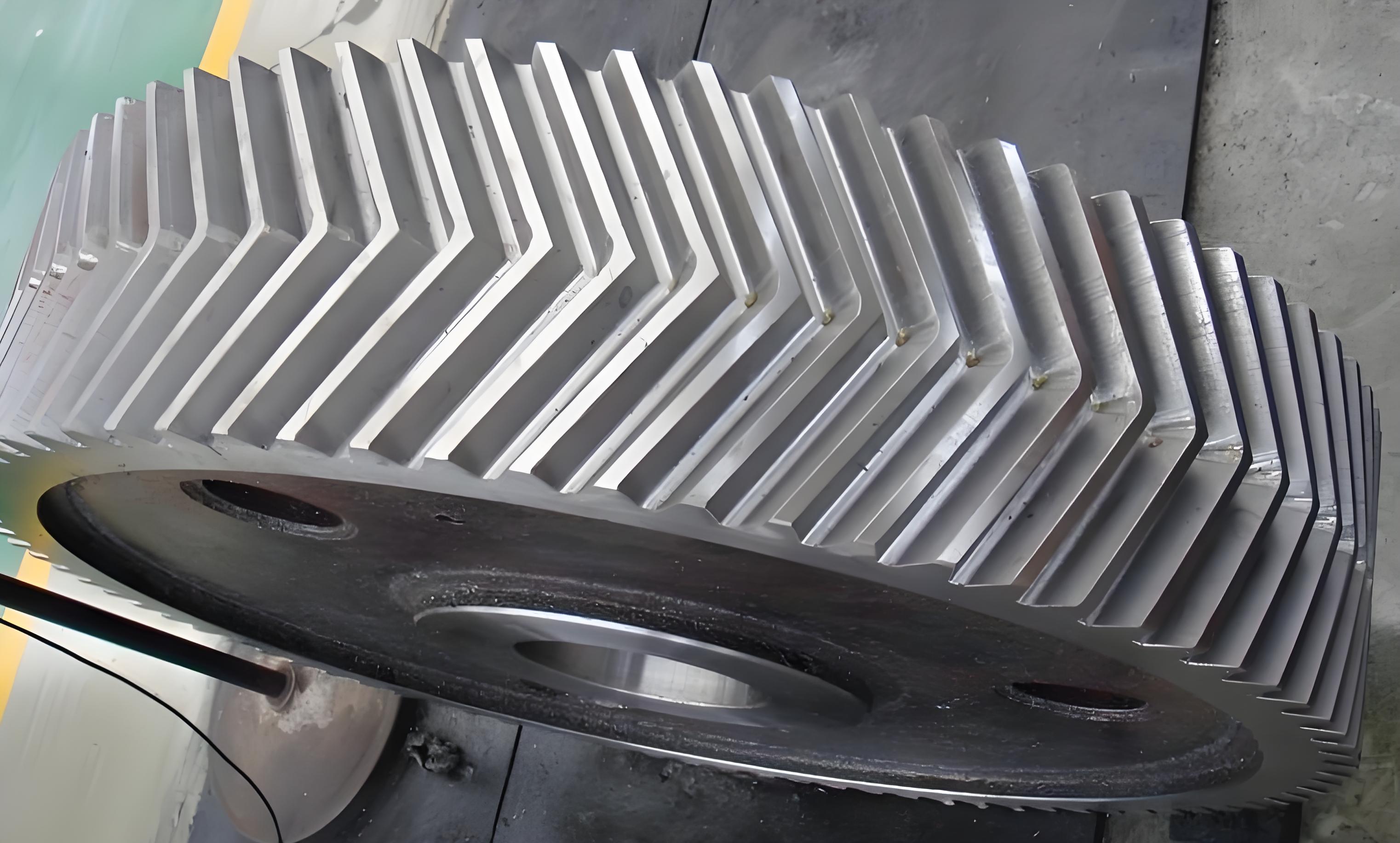
In contrast, the input and intermediate shafts are intentionally designed to allow a small, self-adjusting axial movement. This is a mature and proven design principle. The reason lies in the nature of the herringbone gear itself. Despite advances in manufacturing, inherent errors in machining, heat treatment distortion, and assembly tolerances are unavoidable. These errors can cause the left-hand and right-hand helices of a herringbone gear pair to be misaligned along their theoretical centerline. To ensure proper load distribution across both helices and achieve true line contact, the gear pair must find its own optimal meshing position.
This is accomplished by mounting the input and intermediate shafts on cylindrical roller bearings, which permit axial movement. Upon start-up and initial loading, these shafts will make a slight axial adjustment—a “float”—until the opposing axial forces generated by the left and right helices are balanced, effectively centering the herringbone gear engagement. Once this equilibrium is found, the shafts should remain axially stable. This float is a transient, self-correcting feature, not a continuous motion. Pathological shifting, however, is characterized by large, often reciprocating axial movements that persist during operation, indicating a failure to maintain this delicate force balance, invariably due to component non-conformance or degradation.
2. The Mechanics of Herringbone Gear Meshing and Axial Force Generation
To understand the failure, one must first understand the forces at play in a properly functioning herringbone gear reducer. The double-circular-arc tooth profile is chosen for its high load-carrying capacity and favorable lubrication entrainment. The axial force component (F_a) generated by a single helical gear is given by:
$$F_a = F_t \cdot \tan(\beta)$$
Where $F_t$ is the tangential force (transmitted load) and $\beta$ is the helix angle. In a herringbone gear, the two helices are opposed. Therefore, the theoretical net axial force is:
$$F_{a\_net} = F_{t,L} \cdot \tan(\beta_L) – F_{t,R} \cdot \tan(\beta_R)$$
For a symmetrically cut and perfectly aligned herringbone gear with equal load sharing ($F_{t,L} = F_{t,R}$ and $\beta_L = \beta_R$), $F_{a\_net}$ equals zero. This ideal cancellation is the primary advantage. However, manufacturing deviations mean $\beta_L \neq \beta_R$ in practice. Furthermore, misalignment prevents equal load sharing ($F_{t,L} \neq F_{t,R}$). The design-intent axial float allows the system to minimize the residual $F_{a\_net}$ by physically shifting the shaft until the forces find a new balance point, often where contact patterns on both helices are equalized.
The torsional load is transmitted from the shaft to the gear primarily through a high-interference fit. The keyway, while present, primarily serves for angular positioning and back-up torque transmission; the fit is designed to carry the full torque via friction. The contact pressure ($p_c$) at the interference fit interface is derived from thick-walled cylinder theory:
$$p_c = \frac{\delta}{d \cdot \left( \frac{C_1}{E_1} + \frac{C_2}{E_2} \right)}$$
Where $\delta$ is the diametral interference, $d$ is the nominal diameter, $E$ is the modulus of elasticity, and $C$ is a constant based on the geometry of the hub and shaft ($C = \frac{1 + Q^2}{1 – Q^2} + \nu$ for the hub, and $C = 1 – \nu$ for the solid shaft, where $Q$ is the ratio of inner to outer diameter and $\nu$ is Poisson’s ratio). The torque capacity ($T_{fit}$) of this interference fit is:
$$T_{fit} = \frac{1}{2} \pi \mu p_c L d^2$$
Where $\mu$ is the coefficient of friction and $L$ is the engagement length. The reducer’s design must ensure that $T_{fit}$ significantly exceeds the maximum applied cyclic torque $T_{applied}$ with a sufficient safety factor to withstand billions of load reversals without fretting or micro-motion.
3. Root Cause Analysis of Pathological Axial Shifting
Pathological shifting occurs when the equilibrium maintained by the interference fit and gear meshing forces is lost. The most prevalent trigger is at the dead points of the pumping cycle, where the direction of torque reverses. If the interference fit on one of the large herringbone gears on the intermediate shaft has degraded or was insufficient from the start, that gear will momentarily lag or slip relative to the shaft when the torque crosses zero. This rotational lag, often just a minute angle $\epsilon$, creates a phase difference between the two large gears. The axial force from the still-tight gear pushes the pinion (input) shaft axially. Only when the lagging gear catches up and both gears share the load does the axial force re-balance, snapping the pinion shaft back. This cycle repeats with every stroke, causing a reciprocating axial shift.
The root causes can be systematically categorized and are directly linked to reducer quality. The following table summarizes the observed shift patterns and their primary associated causes:
| Shift Pattern | Observed Behavior | Primary Root Causes |
|---|---|---|
| Uniform, Slow Shifting | Input shaft drifts slowly to one extreme, pauses, then drifts slowly back. | Systematic helix angle error across the herringbone gear tooth flank; asymmetric wear on left vs. right helices; persistent gear misalignment due to housing bore errors. |
| Slow, Jumpy Shifting | Slow drift interrupted by a sudden jump, continues to extreme, pauses, and repeats on return. | Localized gear errors such as a distorted tooth, a small step in tooth thickness, or the early stages of a tooth crack (spalling) causing discontinuous engagement. |
| Uniform, Rapid Shifting (Per Stroke) | One or two quick, sharp shifts per crank revolution, typically near dead points. | Insufficient interference fit on the intermediate shaft gears, allowing micro-slip under torque reversal. Aggravated by poor unit balance leading to high reverse torque. |
| Erratic, Forced Shifting | Rapid, forceful shifting not strictly tied to stroke cycle, sometimes accompanied by heavy vibration. | Severe external misalignment from a bent output shaft or failing output bearings; extreme uneven loading from a damaged crank or pitman arm connection, imposing radial loads that distort the housing and alter gear mesh. |
The fundamental reasons behind these failure modes almost universally point to a lapse in quality control during the reducer’s lifecycle:
1. Manufacturing and Assembly Deficiencies: This is the predominant cause. Inadequate process control leads to components that do not meet drawing specifications.
- Gear Quality: Helix angle ($\beta$) deviations beyond tolerance, tooth profile errors, excessive runout, and improper heat treatment leading to inadequate hardness or residual stresses.
- Shaft and Fit Quality: Incorrect shaft diameters or bore sizes resulting in an interference fit ($\delta$) below the design minimum. The actual $p_c$ and thus $T_{fit}$ are below required levels. Surface finish of the mating parts is also critical for maintaining $\mu$.
- Housing Quality: Misaligned or non-parallel bore centers for the bearings and gears, preventing proper herringbone gear alignment from the outset.
2. Material and Metallurgical Flaws: Substandard material or processing.
- Using grades of steel unsuited for high-cycle fatigue.
- Cast gears with subsurface defects like shrinkage cavities, porosity, or inclusions that act as stress concentrators and lead to premature pitting or tooth breakage.
- Insufficient core hardness, allowing the tooth root to yield or the bore to deform under the interference fit pressure.
3. Operational and Maintenance Factors: While not a manufacturing defect, improper use accelerates failure.
- Poor Pumping Unit Balance: Creates large reverse torque loads ($-T_{applied}$) that double the effective stress range on the interference fit, drastically accelerating fatigue.
- Lubrication Failure: Contaminated or degraded oil leads to abrasive wear, scoring tooth flanks and altering the meshing pattern, which changes axial force distribution.
- Overloading: Exceeding the reducer’s rated torque directly challenges the safety factor of the interference fit.
The cyclical nature of the loading is key to understanding the failure mechanism. The repeated torque reversal can lead to fretting corrosion at the gear-shaft interface if the contact pressure is marginal. The fretting wear debris removes material, effectively increasing the clearance and reducing $\delta$, which in turn lowers $p_c$ and $T_{fit}$ in a vicious cycle. This degradation can be modeled as a wear rate proportional to the micro-slip amplitude and contact pressure.
$$V = k \cdot s \cdot p_c \cdot N$$
Where $V$ is wear volume, $k$ is a wear coefficient, $s$ is slip amplitude, and $N$ is the number of cycles. Once started, this process is self-propagating and leads to the rapid, per-stroke shifting observed.
4. Comprehensive Quality Gates for Herringbone Gear Reducer Reliability
Preventing axial shifting requires a holistic quality assurance approach targeting every stage, from design to field maintenance. The following table outlines critical control measures:
| Stage | Critical Control Point | Measurement/Standard |
|---|---|---|
| Design | Interference Fit Calculation | Safety factor for $T_{fit}$ must account for 90M+ fully reversed cycles. Use conservative $\mu$ values. Specify press-fit forces. |
| Manufacturing | Gear Tooth Geometry | 100% inspection of helix angle ($\beta$), profile, and lead via gear CMM. Tighter tolerances than for standard industrial gears. |
| Shaft & Gear Bore Dimensions | Statistical process control (SPC) on diameters to ensure $\delta$ is within specified range, not just minimum. | |
| Material & Heat Treat | Certification for steel grade. Hardness verification on tooth flank, root, and bore. Non-destructive testing (NDT) for defects. | |
| Housing Bores | CMM verification of centerline parallelism, coaxiality, and distance. | |
| Assembly | Press-Fit Procedure | Controlled hydraulic pressing to specified force/position. Record final assembly dimensions. |
| Pre-Assembly Alignment | Check and shim bearing seats as needed to ensure gear alignment before final closure. | |
| Field Service | Balancing | Regular check and adjustment of pumping unit counterbalance to minimize reverse torque. |
| Lubrication Analysis | Regular oil analysis for wear metals and contamination. |
For a newly assembled reducer, a simple diagnostic test can be performed. By marking the shaft and gear relative to each other and running the reducer under loaded conditions (e.g., on a test stand) for a short period, any relative rotation (indicating fit slippage) can be detected upon disassembly before the unit is ever placed in service.
5. Conclusion
The axial behavior of a beam pumping unit reducer is a definitive indicator of its internal health and manufacturing quality. The designed axial float in the input and intermediate shafts is a sophisticated and necessary feature for achieving optimal herringbone gear meshing, allowing the double-helix system to self-center and distribute loads evenly. This is a hallmark of good engineering design for this specific, demanding application.
Conversely, any persistent, reciprocating, or large-amplitude axial shifting is a failure symptom, not a design feature. The root cause analysis consistently leads back to a failure to maintain the integrity of the interference fit between the herringbone gears and their shafts under high-cycle, fully reversed loading. This failure is overwhelmingly a consequence of quality shortfalls: insufficient interference from out-of-tolerance parts, material defects, gear geometry errors, or improper assembly. Therefore, the presence of pathological axial shifting is a reliable, field-observable sign that the reducer is a non-conforming product. Eliminating this fault requires a rigorous, disciplined approach to every aspect of design, material selection, manufacturing precision, and assembly verification, ensuring that every herringbone gear reducer can withstand a hundred million load cycles as intended.