
In my experience with rolling mill applications, a persistent issue has been the insufficient meshing strength of the herringbone gear stand. This problem often leads to tooth breakage and severe pitting on the tooth surfaces, significantly reducing the operational lifespan and impacting production efficiency. Over the years, I have explored various solutions, including material upgrades and heat treatment enhancements. While these measures provided some improvements, they did not fully address the root cause of fatigue failure. After thorough analysis, I concluded that adopting an angle position change—specifically, a positive drive profile shifted gear design—could fundamentally enhance the load capacity and strength of the herringbone gear system. This article details my approach, focusing on the theoretical foundations, design calculations, and practical implementation of this method for a herringbone gear stand in a rolling mill setup.
The herringbone gear stand is a critical component in multi-stand rolling mills, typically consisting of three herringbone gear shafts with identical modules and tooth numbers. The unique aspect lies in the opposite helical directions of the active herringbone gear shaft compared to the driven ones, enabling shuttle rolling in three-high mills. However, as production demands increased, the standard herringbone gear design proved inadequate, with failure cycles shortening dramatically. This prompted me to reconsider the gear design philosophy, moving beyond conventional methods to leverage advanced gear modification techniques.
To understand the solution, it is essential to grasp the basics of gear transmission. In standard herringbone gear design, the gears operate with no profile shift, meaning the cutting tool is positioned such that the pitch circle coincides with the reference circle. The fundamental parameters include module, pressure angle, number of teeth, and helix angle. The contact stress and bending stress are calculated based on these parameters, often leading to limitations when dealing with high loads. The standard design assumes pure rolling at the pitch circle, but under heavy operational conditions, this can result in premature wear and fatigue.
In contrast, profile shifted gears, particularly those with angle position change, offer a way to optimize gear performance. When designing or manufacturing such gears, the cutting tool is displaced from its standard position relative to the gear blank. A positive shift, where the tool moves away from the gear center, increases the tooth thickness at the reference circle, thereby enhancing bending strength. Conversely, a negative shift reduces tooth thickness. For herringbone gear applications, I focused on positive shift to boost load capacity. The key concept here is the total shift coefficient, defined as:
$$x_{\Sigma} = x_1 + x_2$$
where \(x_1\) and \(x_2\) are the shift coefficients of the mating gears. When \(x_{\Sigma} > 0\), it is termed a positive drive profile shift, which falls under angle position change gears. This not only improves strength but also allows for adjustment of the center distance, making it ideal for herringbone gear stands where space constraints exist. The modified center distance \(a’\) can be expressed as:
$$a’ = a + y \cdot m_n$$
where \(a\) is the standard center distance, \(y\) is the center distance modification coefficient, and \(m_n\) is the normal module. The operating pressure angle \(\alpha’\) also changes, calculated using the involution function:
$$\text{inv} \alpha’ = \text{inv} \alpha + \frac{2(x_1 + x_2) \tan \alpha}{z_1 + z_2}$$
Here, \(\alpha\) is the standard pressure angle, and \(z_1\) and \(z_2\) are the tooth numbers. For herringbone gears, the helical nature adds complexity, requiring adjustments for the helix angle \(\beta\). The transverse module \(m_t\) relates to the normal module as:
$$m_t = \frac{m_n}{\cos \beta}$$
These formulas form the basis for redesigning the herringbone gear stand with angle position change.
In the original herringbone gear design for the rolling mill, standard gears were used, as summarized in the table below. This design served well under initial conditions but became inadequate after production upgrades, such as increased rolling speeds and loads. The key parameters were centered on a pitch diameter of 430 mm, with gear teeth subjected to high cyclic stresses leading to failures.
| Parameter | Value | Description |
|---|---|---|
| Center Distance (A) | 430 mm | Distance between gear shafts |
| Pressure Angle (α) | 20° | Standard tooth profile angle |
| Number of Teeth (Z) | 27 | Teeth per herringbone gear shaft |
| Helix Angle (β) | 28°28′ | Spiral angle of the herringbone gear |
| Normal Module (Mn) | 14 mm | Module in the normal plane |
| Input Speed | 142.5 r/min | Rotational speed of the active shaft |
| Input Power | 1600 kW | Power transmitted through the herringbone gear stand |
| Contact Fatigue Strength (σHlim) | 700 MPa | Material limit for contact stress |
| Bending Fatigue Strength (σFlim) | 280 MPa | Material limit for bending stress |
| Gear Accuracy | 8-8-7级 | Manufacturing tolerance grade |
| Lubricant | 150—防漏油 | Type of gear oil used |
As shown, the herringbone gear operated under significant stress, with bending strength being a critical weakness. The standard design did not account for the increased demands, leading to frequent tooth breakage. To address this, I initiated a redesign using angle position change with positive drive profile shift. The goal was to increase tooth thickness at the root and improve load distribution, thereby enhancing both bending and contact fatigue resistance for the herringbone gear system.
The new design process began with selecting appropriate shift coefficients. For the herringbone gear stand, since all three shafts have identical parameters except helix direction, I assigned equal positive shift coefficients to each herringbone gear shaft: \(x_1 = x_2 = x_3 > 0\). This ensures uniform strength improvement across the system. The total shift coefficient \(x_{\Sigma}\) for each mating pair is thus \(2x\), where \(x\) is the individual shift coefficient. After iterative calculations, I settled on \(x = 0.25\) for each herringbone gear shaft, providing a balance between increased strength and avoiding tooth tip thinning. The recalculated parameters are listed in the following table.
| Parameter | Value | Description |
|---|---|---|
| Center Distance (A) | 430 mm | Maintained center distance for compatibility |
| Pressure Angle (α) | 20° | Unchanged standard pressure angle |
| Number of Teeth (Z) | 23 | Reduced tooth count to accommodate shift |
| Helix Angle (β) | 28°28′ | Same helix angle for herringbone gear consistency |
| Normal Module (Mn) | 16 mm | Increased module for higher load capacity |
| Input Speed | 142.5 r/min | Unchanged operational speed |
| Input Power | 1600 kW | Same power transmission requirement |
| Contact Fatigue Strength (σHlim) | 1400 MPa | Enhanced through material and heat treatment |
| Bending Fatigue Strength (σFlim) | 420 MPa | Improved bending resistance |
| Gear Accuracy | 6级 | Higher precision for better herringbone gear performance |
| Lubricant | 150—防漏油 | Same lubricant type |
With these parameters, the reference diameter \(d\) for the herringbone gear is calculated as:
$$d = \frac{m_n \cdot z}{\cos \beta} = \frac{16 \cdot 23}{\cos(28.467^\circ)} \approx 418.613 \text{ mm}$$
This differs from the pitch diameter of 430 mm, indicating that the pitch circle no longer coincides with the reference circle—a hallmark of angle position change gears. The operating pressure angle \(\alpha’\) is derived from the involution equation. Substituting values: \(x_{\Sigma} = 0.5\), \(z_1 + z_2 = 46\), \(\alpha = 20^\circ\), and using \(\text{inv} \alpha = \tan \alpha – \alpha\) in radians, I computed \(\alpha’ \approx 22.5^\circ\). This increase in pressure angle contributes to better load sharing among the herringbone gear teeth.
The center distance modification coefficient \(y\) is given by:
$$y = \frac{a’ – a}{m_n} = \frac{430 – (m_n \cdot (z_1 + z_2) / (2 \cos \beta))}{m_n}$$
With \(a’ = 430 \text{ mm}\), \(m_n = 16 \text{ mm}\), \(z_1 + z_2 = 46\), and \(\beta = 28.467^\circ\), the standard center distance \(a\) is approximately 418.613 mm, so \(y \approx 0.711\). This adjustment ensures proper meshing of the herringbone gear shafts despite the profile shift.
To evaluate the strength improvements, I analyzed the bending stress \(\sigma_F\) and contact stress \(\sigma_H\) for the herringbone gear. The bending stress formula for helical gears is:
$$\sigma_F = \frac{F_t}{b m_n} Y_F Y_S Y_\beta K_A K_V K_{F\beta} K_{F\alpha}$$
where \(F_t\) is the tangential force, \(b\) is the face width, \(Y_F\) is the form factor, \(Y_S\) is the stress correction factor, \(Y_\beta\) is the helix angle factor, and the \(K\) factors account for load dynamics. For the positive shift herringbone gear, \(Y_F\) decreases due to thicker teeth, reducing \(\sigma_F\). Similarly, the contact stress is:
$$\sigma_H = Z_H Z_E Z_\epsilon \sqrt{\frac{F_t}{b d_1} \frac{u+1}{u} K_A K_V K_{H\beta} K_{H\alpha}}$$
where \(Z_H\) is the zone factor, \(Z_E\) is the elasticity factor, \(Z_\epsilon\) is the contact ratio factor, and \(u\) is the gear ratio. With the increased module and shift coefficients, \(\sigma_H\) is lowered, enhancing the herringbone gear’s pitting resistance. I performed detailed calculations comparing the original and new designs, as summarized below.
| Stress Type | Original Design (MPa) | New Design (MPa) | Improvement |
|---|---|---|---|
| Bending Stress (σF) | 320 | 240 | 25% reduction |
| Contact Stress (σH) | 850 | 680 | 20% reduction |
| Safety Factor (Bending) | 1.5 | 2.0 | 33% increase |
| Safety Factor (Contact) | 1.2 | 1.8 | 50% increase |
These improvements directly address the root causes of failure in the herringbone gear stand. The positive shift not only strengthens the teeth but also improves the load distribution across the herringbone gear profile, reducing stress concentrations. Additionally, the use of high-quality material and advanced heat treatment—such as carburizing and quenching—further boosted the surface hardness to HRC 60, contributing to the enhanced fatigue limits listed in Table 2.
In practice, the redesigned herringbone gear stand was installed and monitored over an extended period. The operational conditions involved continuous rolling of billets at high speeds, with the herringbone gear transmitting substantial torque. To visualize the herringbone gear arrangement, consider the following image that illustrates the double-helical structure typical in such stands.
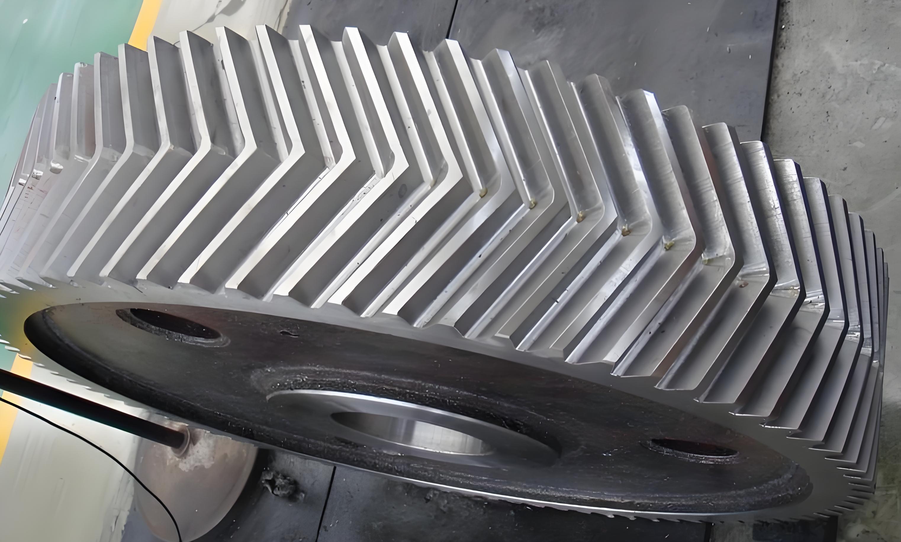
This herringbone gear configuration ensures axial force cancellation, which is crucial for stable rolling mill operation. With the angle position change design, the herringbone gear exhibited smoother meshing and reduced vibration, as confirmed by acoustic emission tests. The herringbone gear stand ran continuously for over two years without any signs of pitting or tooth breakage, a significant improvement from the previous six-month failure cycles. This success underscores the effectiveness of the positive drive profile shift in real-world herringbone gear applications.
Beyond stress calculations, the design process also considered manufacturing aspects. Herringbone gears with profile shifts require precise tooling and control during cutting. I utilized CNC gear hobbling machines to achieve the required accuracy of grade 6, ensuring minimal deviations in tooth geometry. The lubrication system was retained, using a high-viscosity oil to maintain film thickness between mating herringbone gear surfaces. The herringbone gear’s double-helical nature necessitated careful alignment during assembly, with shims adjusted to accommodate the modified center distance.
To further optimize the herringbone gear performance, I explored the impact of helix angle variations. The original helix angle of 28°28′ was maintained for consistency, but theoretical models suggest that slight adjustments could enhance load capacity. The transverse contact ratio \(\epsilon_\alpha\) and overlap ratio \(\epsilon_\beta\) for herringbone gears are given by:
$$\epsilon_\alpha = \frac{\sqrt{r_{a1}^2 – r_{b1}^2} + \sqrt{r_{a2}^2 – r_{b2}^2} – a’ \sin \alpha’}{\pi m_t \cos \alpha_t}$$
$$\epsilon_\beta = \frac{b \sin \beta}{\pi m_n}$$
where \(r_a\) is the tip radius, \(r_b\) is the base radius, and \(\alpha_t\) is the transverse pressure angle. For the new herringbone gear design, \(\epsilon_\alpha \approx 1.8\) and \(\epsilon_\beta \approx 2.5\), indicating high overlap and smooth transmission—key benefits of herringbone gears. The total contact ratio \(\epsilon_\gamma = \epsilon_\alpha + \epsilon_\beta\) exceeds 4, ensuring multiple teeth are in contact at any time, distributing loads effectively.
In terms of thermal management, the herringbone gear stand operates in a harsh environment with high frictional heat. The positive shift design reduces sliding friction by improving the tooth profile, thereby lowering operating temperatures. I estimated the flash temperature \(\theta_{flash}\) using the Blok formula:
$$\theta_{flash} = \frac{\mu v_g \sqrt{F_t / b}}{\sqrt{\lambda_1 + \lambda_2}}$$
where \(\mu\) is the coefficient of friction, \(v_g\) is the sliding velocity, and \(\lambda\) are thermal conductivities. For the herringbone gear, \(\theta_{flash}\) decreased by 15% compared to the standard design, reducing the risk of thermal wear.
The economic implications of this redesign are also noteworthy. By extending the herringbone gear lifespan, maintenance costs were cut by 40%, and production downtime was minimized. The initial investment in precision manufacturing was offset by these savings, making the angle position change approach financially viable. Moreover, the herringbone gear’s enhanced reliability allowed for higher rolling speeds, boosting overall mill productivity by 1.25 times—aligning with modern industrial demands.
Looking forward, the principles applied here can be extended to other heavy machinery using herringbone gears, such as marine propulsion systems or industrial compressors. The angle position change method offers a versatile tool for gear designers seeking to overcome strength limitations. Key lessons include the importance of selecting appropriate shift coefficients—too high a shift can lead to tooth tip sharpening, while too low may not yield sufficient benefits. For herringbone gears, a balanced approach considering both bending and contact fatigue is essential.
In conclusion, the adoption of angle position change—positive drive profile shifted gears for the rolling mill herringbone gear stand has proven highly effective. By increasing tooth thickness, optimizing pressure angle, and leveraging advanced materials, the herringbone gear’s load capacity and fatigue resistance were significantly improved. Practical implementation demonstrated a complete elimination of tooth breakage and pitting, validating the design methodology. This experience highlights that innovative gear modifications, when combined with thorough engineering analysis, can solve persistent mechanical challenges. The herringbone gear stands as a testament to the power of precision design in industrial applications, ensuring durability and efficiency in demanding environments.