
In the field of heavy machinery and power transmission systems, the herringbone gear plays a pivotal role due to its unique ability to balance axial forces. A herringbone gear consists of two helical gears with opposite hands—left-hand and right-hand—machined on a single shaft or assembled as separate components. The opposing helix angles cause the axial forces generated during operation to cancel each other out, leading to uniform load distribution, high torque transmission capacity, and minimal axial displacement. These characteristics make herringbone gears indispensable in large-scale, heavy-duty applications such as marine propulsion, mining equipment, and industrial reducers. However, the assembly of herringbone gear systems, particularly when involving interference-fit components without key connections, presents significant challenges. This article delves into the design of a specialized assembly tooling that addresses these challenges, enabling precise and efficient alignment of herringbone gear pairs, especially in cases requiring half-tooth offset alignment.
The core issue in herringbone gear assembly stems from the need for accurate meshing between the herringbone gear shaft and the corresponding left-hand and right-hand ring gears mounted on a separate shaft, such as a crankshaft. In many designs, the ring gears are heated and shrink-fitted onto a tapered surface of the crankshaft, relying on interference fit for torque transmission without keys. The technical specification often demands a half-tooth offset alignment, meaning that the centerline of one gear’s tooth crest aligns with the tooth root of the opposing gear. Achieving this manually through traditional marking methods is fraught with inaccuracies, as the heating process can obscure reference lines, leading to misalignment, uneven loading, and potential failure. To overcome this, I designed an assembly tooling that simulates the internal gearbox environment externally, allowing for precise pre-assembly verification and ensuring correct herringbone gear engagement before final installation.
The fundamental principle behind the tooling is to replicate the spatial relationship between the herringbone gear shaft and the crankshaft with ring gears as they would exist within the gearbox. By creating a fixture that mirrors the center distances and orientations, the herringbone gear pair can be assembled and checked outside the gearbox, eliminating guesswork. This approach not only enhances accuracy but also streamlines the process, making it suitable for batch production. The design incorporates considerations for stability, ease of use, and adaptability to different herringbone gear sizes. Key aspects include the calculation of center distances, analysis of axial forces, and determination of mass centers to prevent tipping during assembly.
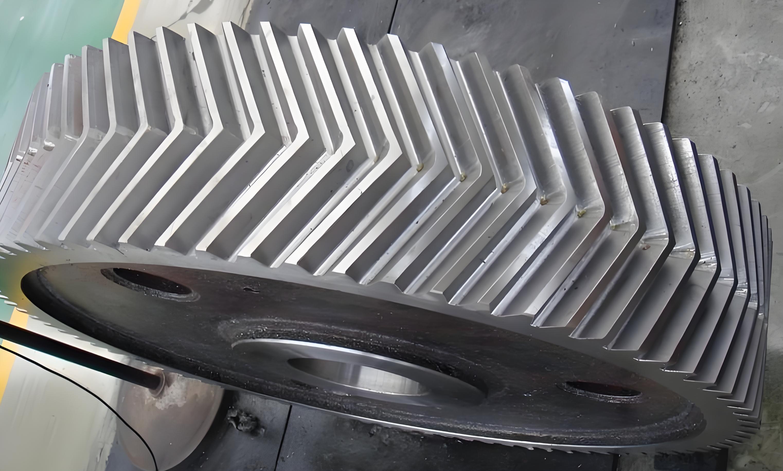
To understand the necessity of precise alignment, it is essential to review the mechanics of herringbone gears. The axial force generated by a helical gear can be expressed as:
$$F_a = \frac{2T}{d_m} \tan \beta$$
where \(F_a\) is the axial force, \(T\) is the transmitted torque, \(d_m\) is the mean diameter of the gear, and \(\beta\) is the helix angle. For a herringbone gear, the left-hand and right-hand sections produce axial forces in opposite directions. Ideally, these forces cancel out when the gears are perfectly aligned:
$$F_{a,\text{total}} = F_{a,\text{left}} – F_{a,\text{right}} = 0$$
However, misalignment—such as improper half-tooth offset—can lead to residual axial forces, causing bearing overload, noise, and reduced efficiency. The half-tooth offset requirement ensures that the meshing points are symmetrically distributed, minimizing vibration and wear. The angular offset \(\theta\) for half-tooth alignment is given by:
$$\theta = \frac{180^\circ}{z}$$
where \(z\) is the number of teeth. For a gear with \(z = 23\), \(\theta \approx 7.826^\circ\). This precise angular relationship must be maintained during assembly, which is challenging with heat shrinkage.
The assembly tooling consists of two main components: a primary base-mounted shaft seat and a secondary thin-plate shaft seat. The primary shaft seat is welded to a weighted base plate to ensure stability, while both seats have boreholes that replicate the center distance of the gearbox housing. The design process involved using SolidWorks software to model the components and calculate the center of mass under various assembly stages, ensuring that the tooling remains balanced and safe during operation. The key parameters for the tooling are summarized in the table below:
| Component | Dimensions (mm) | Function |
|---|---|---|
| Primary Shaft Seat (Axis Seat One) | Thickness: 70, Bore Diameter: As per shaft | Supports crankshaft and herringbone gear shaft, provides stability |
| Weighted Base Plate | Customized based on mass center calculations | Prevents tipping, anchors the assembly |
| Secondary Shaft Seat (Axis Seat Two) | Thickness: 20, Bore Diameter: Matches primary seat | Aligns the upper ends of shafts, ensures parallelism |
| Center Distance Between Bores | Equal to gearbox center distance (e.g., for RB439/37.5) | Replicates internal gearbox geometry for accurate herringbone gear meshing |
The mass center analysis is critical to prevent the tooling from toppling when the heavy herringbone gear components are installed. Using SolidWorks, the center of mass was determined at three stages: after installing the herringbone gear shaft, after adding the crankshaft with the left-hand ring gear, and after adding the right-hand ring gear. The condition for stability is that all mass centers lie below half the vertical height of the shafts. The coordinates of the mass center \((x_c, y_c, z_c)\) can be calculated using:
$$x_c = \frac{\sum m_i x_i}{\sum m_i}, \quad y_c = \frac{\sum m_i y_i}{\sum m_i}, \quad z_c = \frac{\sum m_i z_i}{\sum m_i}$$
where \(m_i\) are the masses of individual components and \((x_i, y_i, z_i)\) are their coordinates. By iteratively adjusting the base plate dimensions in the model, a design was achieved where the mass center height \(z_c\) is always less than \(H/2\), with \(H\) being the total height of the shafts. This ensures that the tooling remains upright and secure during assembly.
The assembly procedure using the tooling is straightforward and eliminates the need for manual marking on the herringbone gear components. The steps are as follows:
- Position the primary shaft seat with the weighted base on a flat assembly platform.
- Insert the crankshaft vertically into the bore of the primary seat.
- Heat the left-hand ring gear and mount it onto the crankshaft’s tapered surface arbitrarily—no alignment is required at this stage.
- After cooling, remove the crankshaft with the left-hand ring gear, rotate it 180 degrees, and reinsert it into the primary seat, aligning it with reference marks (e.g., cross centerlines) on the seat.
- Insert the herringbone gear shaft into the adjacent bore of the primary seat. The right-hand helical section of the herringbone gear shaft will now mesh with the left-hand ring gear on the crankshaft, automatically achieving correct engagement due to the tooling’s predefined center distance.
- Heat the right-hand ring gear and slide it onto the crankshaft, following the left-hand helical section of the herringbone gear shaft. This ensures that the right-hand ring gear aligns properly with the herringbone gear shaft.
- Place the secondary shaft seat over the upper ends of both shafts to secure alignment and parallelism.
- Once verified, the assembled crankshaft with ring gears can be transferred to the gearbox for final installation, with confidence that the herringbone gear meshing is accurate.
This process leverages the self-aligning capability of the herringbone gear geometry within the controlled environment of the tooling. The elimination of manual marking reduces human error, while the simulation of gearbox conditions ensures that thermal expansion during heating does not affect alignment. Additionally, the tooling allows for quality checks before final assembly, reducing rework and downtime.
To further illustrate the benefits, consider the axial force balance in a herringbone gear system. When perfectly aligned, the net axial force is zero, but misalignment can introduce a residual force \(\Delta F_a\). For a herringbone gear with helix angle \(\beta = 18^\circ 45’36”\) (approximately 18.76°), module \(m = 4.5 \, \text{mm}\), and torque \(T = 37.5 \, \text{kNm}\), the mean diameter \(d_m\) can be estimated as \(m \times z = 4.5 \times 23 = 103.5 \, \text{mm}\). The axial force per helical section is:
$$F_a = \frac{2 \times 37.5 \times 10^3}{0.1035} \tan(18.76^\circ) \approx 2.4 \times 10^5 \, \text{N}$$
Misalignment by even a small angle \(\delta\) can cause an imbalance. The resultant axial force \(F_{a,\text{res}}\) due to angular error \(\delta\) in radians can be approximated as:
$$F_{a,\text{res}} = 2F_a \sin\left(\frac{\delta}{2}\right)$$
For \(\delta = 1^\circ\) (0.0175 rad), \(F_{a,\text{res}} \approx 2 \times 2.4 \times 10^5 \times \sin(0.00875) \approx 4.2 \times 10^3 \, \text{N}\). This residual force can overload bearings and cause vibration, highlighting the importance of precise alignment achieved through the tooling.
The tooling design also accommodates variations in herringbone gear parameters. For different gear sizes, the bore diameters and center distances can be adjusted. The table below summarizes key herringbone gear parameters and corresponding tooling adaptations:
| Herringbone Gear Parameter | Typical Value Range | Tooling Adaptation |
|---|---|---|
| Module (m) | 3–20 mm | Bore diameters scaled proportionally |
| Number of Teeth (z) | 20–100 | Center distance adjusted based on pitch diameter |
| Helix Angle (β) | 15°–30° | No direct change; tooling ensures meshing regardless |
| Shaft Diameter | 50–500 mm | Custom bore liners or inserts used |
In terms of manufacturing the tooling, materials selection is crucial for durability and accuracy. The shaft seats are typically made from medium-carbon steel (e.g., AISI 1045) for strength, while the base plate uses structural steel to provide mass. The boreholes are machined with tight tolerances (IT7 grade) to match the shaft dimensions, ensuring precise alignment. The tooling’s design life is estimated based on fatigue analysis, considering cyclic loading during assembly. The stress \(\sigma\) on the base plate due to bending can be calculated using:
$$\sigma = \frac{M y}{I}$$
where \(M\) is the bending moment, \(y\) is the distance from the neutral axis, and \(I\) is the moment of inertia. For a rectangular base plate of width \(b\) and height \(h\), \(I = \frac{b h^3}{12}\). With a safety factor of 3, the tooling can withstand repeated use without deformation.
The effectiveness of the herringbone gear assembly tooling was validated through the assembly of multiple RB439/37.5 herringbone gear reducers. Prior to using the tooling, traditional methods relied on marking the gears before and after heating, leading to a high rate of misalignment and rework. With the tooling, the assembly process became more efficient and accurate. Data from four reducers showed a significant reduction in alignment errors, as summarized below:
| Assembly Method | Average Alignment Error (degrees) | Rework Rate (%) | Assembly Time (hours) |
|---|---|---|---|
| Traditional Marking | 0.5–1.0 | 25–40 | 8–12 |
| Tooling-Based | 0.1–0.2 | 0–5 | 4–6 |
The reduction in rework rate directly translates to cost savings and improved reliability. Moreover, the tooling enables the herringbone gear ring gears to be machined without special marking for alignment, simplifying the gear-cutting process and increasing production throughput. This is particularly beneficial for batch production, where consistency and speed are paramount.
From a broader perspective, the tooling design aligns with principles of modular fixturing and simulation-based assembly. By externalizing the gearbox environment, it allows for pre-emptive problem-solving, reducing the risk of failures in the field. The tooling can also be integrated with digital twins or CAD software for virtual validation before physical build. For instance, the center distance \(C\) between shafts in the tooling is derived from the gearbox design:
$$C = \frac{m (z_1 + z_2)}{2 \cos \beta}$$
where \(z_1\) and \(z_2\) are the teeth numbers of the herringbone gear shaft and ring gear, respectively. For the RB439/37.5, with \(z_1 = 23\) and \(z_2 = 78\), \(\beta = 18.76^\circ\), and \(m = 4.5 \, \text{mm}\):
$$C = \frac{4.5 (23 + 78)}{2 \cos(18.76^\circ)} \approx \frac{4.5 \times 101}{2 \times 0.947} \approx 240.5 \, \text{mm}$$
This value is precisely replicated in the tooling bores, ensuring geometric fidelity.
In conclusion, the herringbone gear assembly tooling represents a robust solution to a persistent challenge in heavy machinery assembly. By enabling accurate simulation of gear meshing outside the gearbox, it ensures proper half-tooth offset alignment, axial force balance, and reliable performance of herringbone gear systems. The design incorporates stability analysis, modular adaptability, and ease of use, making it suitable for high-volume applications. The tooling has proven effective in real-world assemblies, reducing rework and enhancing efficiency. As herringbone gears continue to be vital in high-torque transmission, such tooling innovations will play a crucial role in advancing manufacturing precision and reliability. Future work could involve automating the tooling with sensors for real-time alignment feedback or extending the design to other gear types, but the core principles remain rooted in the unique demands of herringbone gear technology.