
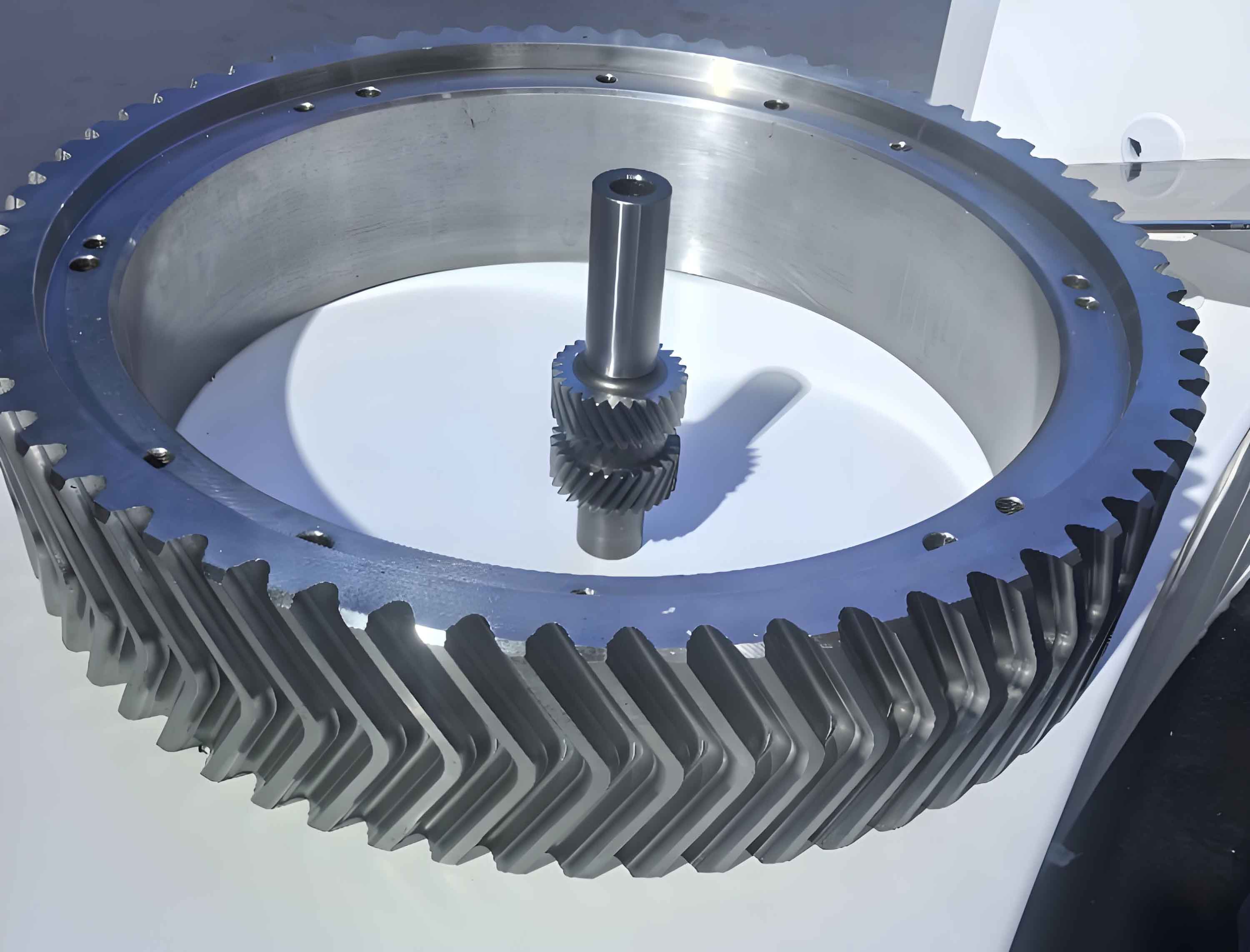
In the field of mechanical engineering, the study of vibration characteristics in gear systems is crucial for optimizing performance and reducing noise. My focus is on a specific type of gear system: the encased differential herringbone gear train, commonly used in high-power applications such as marine reducers. The herringbone gear, with its unique double-helical structure, offers advantages like smooth operation and high load capacity, but its dynamic behavior under various conditions requires thorough investigation. In this article, I will present a comprehensive analysis of the free vibration properties of such a system, considering factors like rotational speed effects and modal patterns.
The motivation for this work stems from the need to understand the complex dynamics of herringbone gear systems in planetary configurations. While previous studies have explored single-stage spur or helical gear trains, the encased differential herringbone gear train, which involves power splitting and multiple stages, presents unique challenges. By developing a detailed dynamic model and analyzing its natural frequencies and modes, I aim to provide insights that can guide the design of more efficient and reliable transmission systems. The use of herringbone gears in these setups is particularly beneficial due to their ability to cancel axial forces, simplifying the modeling process by allowing us to focus on planar vibrations.
To begin, I established a lumped-parameter dynamic model for the encased differential herringbone gear train. This model accounts for both torsional and translational vibrations, incorporating the elastic coupling between the two stages: the differential stage and the encased stage. The system consists of key components such as sun gears, planet gears, ring gears, and carriers, all modeled as rigid bodies with mass and inertia properties. For herringbone gears, due to their symmetric structure, axial vibrations are neglected, and only planar motions (horizontal and vertical translations) and rotations are considered. This simplification is valid because the herringbone gear design inherently balances axial forces, making it ideal for reducing complexity in dynamic analyses.
The coordinate systems are defined in rotating frames attached to the planet carriers. For the differential stage, the carrier rotates with an angular velocity, while for the encased stage, the carrier is fixed. This approach allows us to account for Coriolis and centrifugal inertial forces in the equations of motion. The relative displacements at the meshing points for herringbone gears are derived based on gear geometry parameters like pressure angle and helix angle. For example, the relative displacement for an external meshing pair between a sun gear and a planet gear in a herringbone gear system can be expressed as:
$$ \delta_{spi} = (x_s \sin\psi_{si} + y_s \cos\psi_{si} + u_s – x_{pi} \sin\phi – y_{pi} \cos\phi – u_{pi}) \cos\beta_b $$
where \( \delta_{spi} \) is the relative displacement, \( x_s, y_s, u_s \) are displacements of the sun gear, \( x_{pi}, y_{pi}, u_{pi} \) are for the planet gear, \( \psi_{si} \) is the meshing angle, \( \phi \) is the pressure angle, and \( \beta_b \) is the base helix angle. Similar equations apply for internal meshing pairs. These equations highlight the role of herringbone gear parameters in coupling translational and torsional motions.
The overall system has multiple degrees of freedom: 20 torsional degrees from lumped masses and 26 translational degrees from gear bodies. The equations of motion are derived using Newton’s second law, considering stiffness elements from supports, gear meshes, and connections. For instance, the motion equation for the differential sun gear in a herringbone gear setup is:
$$ m_{s1}\ddot{x}_{s1} + \sum_{i=1}^{3} k_{sp1} \delta_{s1pi} \sin\psi_{s1i} \cos\beta_b + k_{s1} x_{s1} = 0 $$
$$ m_{s1}\ddot{y}_{s1} + \sum_{i=1}^{3} k_{sp1} \delta_{s1pi} \cos\psi_{s1i} \cos\beta_b + k_{s1} y_{s1} = 0 $$
$$ m_{eq,s1}\ddot{u}_{s1} + \sum_{i=1}^{3} k_{sp1} \delta_{s1pi} \cos\beta_b – \frac{k_{sin}}{r_{s1}} \left( \frac{u_{cp1}}{r_{cp1}} – \frac{u_{s1}}{r_{s1}} \right) = 0 $$
Here, \( k_{sp1} \) is the meshing stiffness for herringbone gears, and \( k_{s1} \) is the support stiffness. The equivalent mass \( m_{eq,s1} \) is derived from the moment of inertia, ensuring consistency in torsional dynamics. These equations form a matrix representation: \( \mathbf{M}\ddot{\mathbf{X}} + \mathbf{K}\mathbf{X} = \mathbf{P}_0 \), where \( \mathbf{M} \) is the mass matrix, \( \mathbf{K} \) is the stiffness matrix, \( \mathbf{X} \) is the displacement vector, and \( \mathbf{P}_0 \) is the external load vector. This model serves as the foundation for analyzing free vibrations in herringbone gear systems.
Next, I solved the eigenvalue problem \( \omega_i^2 \mathbf{M} \boldsymbol{\Phi}_i = \mathbf{K} \boldsymbol{\Phi}_i \) to determine the natural frequencies and vibration modes. Through this analysis, I identified five distinct vibration modes specific to the encased differential herringbone gear train. These modes are summarized in the table below, which categorizes them based on their characteristics and frequency ranges. The use of herringbone gears influences these modes due to their coupling effects between translation and torsion.
| Vibration Mode | Abbreviation | Key Features | Typical Frequency Range (Hz) |
|---|---|---|---|
| Torsional Vibration Mode | RM | Only torsional motions in central gears; all translational amplitudes zero; herringbone gear planets vibrate identically. | 0 – 1100 |
| Translational Mode of Differential Stage | DTM | Translational motions in differential stage components; torsional amplitudes zero; herringbone gear planets active. | 10 – 2800 |
| Translational Mode of Encased Stage | ETM | Translational motions in encased stage components; other parts stationary; herringbone gear geometry affects stiffness. | 8 – 1300 |
| Planet Mode of Differential Stage | DPM | Only planet gears in differential stage vibrate; occurs if planet count >3; herringbone gear design influences mode shape. | N/A (not present in example) |
| Planet Mode of Encased Stage | EPM | Only planet gears in encased stage vibrate; multiplicity depends on planet count; herringbone gear parameters critical. | 386 – 1400 |
The torsional vibration mode (RM) involves pure rotational oscillations of all central gears, such as sun gears and ring gears, with no lateral movements. This mode is significant because it reflects the overall torsional flexibility of the herringbone gear train, which can be affected by the helical angles in herringbone gears. For the differential stage translational mode (DTM), the vibrations are confined to the differential stage, where herringbone gear planets exhibit coupled motions. Similarly, the encased stage translational mode (ETM) isolates vibrations to the encased stage, highlighting the decoupling between stages due to the fixed carrier in herringbone gear arrangements.
Planet modes (DPM and EPM) are unique to systems with more than three planets. In my analysis, the encased stage has five herringbone gear planets, leading to EPM modes with multiplicities equal to the number of planets minus three. These modes involve independent vibrations of planet gears, which are influenced by the herringbone gear’s meshing stiffness and support conditions. The absence of DPM in the differential stage (with three planets) underscores the role of planet count in modal behavior for herringbone gear systems.
To quantify these modes, I computed natural frequencies using system parameters typical for a marine reducer. The table below lists the frequencies for different modes, based on a sample parameter set. The herringbone gear parameters, such as helix angle and pressure angle, are embedded in the stiffness calculations.
| RM Frequencies (Hz) | DTM Frequencies (Hz) | ETM Frequencies (Hz) | EPM Frequencies (Hz) |
|---|---|---|---|
| 0.00 | 1155.52 | 7.93 | 386.35 |
| 73.81 | 1307.32 | 10.51 | 717.91 |
| 229.99 | 1794.81 | 54.75 | 1402.68 |
| 426.50 | 2080.50 | 411.64 | 1463.15 |
| 637.54 | 2162.27 | 754.00 | |
| 701.09 | 2778.11 | 1161.42 | |
| 712.20 | 3841.29 | 1224.86 | |
| 1041.29 | 4233.37 | ||
| 1104.48 | 7044.48 |
From this data, I observed that the natural frequencies are relatively densely distributed compared to spur gear systems, due to the larger masses and complex coupling in herringbone gear trains. This density makes it challenging to avoid resonance in operational ranges, emphasizing the need for careful dynamic design in herringbone gear applications.
An important aspect of this study is the effect of rotational speed on natural frequencies. When the system operates at high speeds, Coriolis and centrifugal inertial forces become significant, especially for the differential stage where the carrier rotates. To account for this, I extended the dynamic equation to include these forces: \( \mathbf{M}\ddot{\mathbf{X}} + \Omega_{c1} \mathbf{G} \dot{\mathbf{X}} + (\mathbf{K} – \Omega_{c1}^2 \mathbf{K}_\Omega) \mathbf{X} = \mathbf{P}_0 \), where \( \Omega_{c1} \) is the carrier angular speed, \( \mathbf{G} \) is the gyroscopic matrix, and \( \mathbf{K}_\Omega \) is the centripetal stiffness matrix. For herringbone gear components, the gyroscopic terms depend on mass and geometry.
The eigenvalue problem with speed effects is: \( [-\omega_i^2 \mathbf{M} + j\Omega_{c1}\omega_i \mathbf{G} + (\mathbf{K} – \Omega_{c1}^2 \mathbf{K}_\Omega)] \boldsymbol{\Phi}_i = 0 \). I solved this using perturbation methods, starting from the zero-speed frequencies \( \omega_i(0) \) and computing corrections \( \Delta\omega_i(\Omega_{c0}) \) from the gyroscopic matrix. The adjusted frequencies are given by \( \omega_i(\Omega_{c1}) = \omega_i(0) + \Omega_{c1} \Delta\omega_i(\Omega_{c0}) \). This approach is efficient for herringbone gear systems where analytical solutions are complex.
My analysis revealed that only the DTM modes are affected by rotational speed, due to the rotating carrier in the differential stage. The RM and EPM modes remain unchanged because their gyroscopic couplings are zero or negligible in herringbone gear configurations. For DTM modes, which originally have double roots (i.e., two identical frequencies), the Coriolis and centrifugal forces cause frequency splitting or bifurcation. This means that as speed increases, each double frequency separates into two distinct values. The table below illustrates this phenomenon for different input speeds, based on the example herringbone gear system.
| Input Speed (rpm) | DTM Frequency Pair 1 (Hz) | DTM Frequency Pair 2 (Hz) | DTM Frequency Pair 3 (Hz) | DTM Frequency Pair 4 (Hz) | DTM Frequency Pair 5 (Hz) | DTM Frequency Pair 6 (Hz) |
|---|---|---|---|---|---|---|
| 0 | 10.51, 10.51 | 54.75, 54.75 | 411.64, 411.64 | 754.00, 754.00 | 1161.42, 1161.42 | 1224.86, 1224.86 |
| 2000 | 9.50, 11.33 | 53.07, 56.81 | 410.18, 413.43 | 753.04, 754.79 | 1160.88, 1162.28 | 1221.95, 1226.16 |
| 4000 | 8.49, 12.16 | 51.38, 58.86 | 408.71, 415.22 | 752.08, 755.58 | 1159.79, 1163.15 | 1219.04, 1227.45 |
| 6000 | 7.49, 12.98 | 49.69, 60.92 | 407.24, 417.00 | 751.13, 756.36 | 1159.25, 1164.02 | 1216.14, 1228.75 |
| 8000 | 6.49, 13.80 | 48.00, 62.97 | 405.78, 418.80 | 750.17, 757.15 | 1158.70, 1164.89 | 1213.23, 1230.05 |
| 10000 | 5.49, 14.63 | 46.32, 65.03 | 404.31, 420.58 | 749.21, 757.94 | 1158.70, 1165.78 | 1210.25, 1231.37 |
This bifurcation phenomenon is critical for high-speed herringbone gear trains, as it can lead to unexpected resonances if not accounted for in design. The separation increases with speed, highlighting the importance of considering rotational effects in dynamic analyses of herringbone gear systems. For instance, in marine applications where herringbone gear reducers operate at variable speeds, this frequency splitting must be monitored to avoid vibrational issues.
To further elucidate the dynamics, I derived the gyroscopic matrix \( \mathbf{G} \) and centripetal stiffness matrix \( \mathbf{K}_\Omega \) for herringbone gear components. For a typical gear element with mass \( m_j \), the gyroscopic submatrix is:
$$ \mathbf{G}_j = \begin{pmatrix} 0 & -2m_j & 0 \\ 2m_j & 0 & 0 \\ 0 & 0 & 0 \end{pmatrix} $$
and the centripetal stiffness submatrix is:
$$ \mathbf{K}_{\Omega j} = \begin{pmatrix} m_j & 0 & 0 \\ 0 & m_j & 0 \\ 0 & 0 & 0 \end{pmatrix} $$
These matrices are incorporated into the system matrices for the differential stage components, such as the sun gear, ring gear, and planets in herringbone gear arrangements. The encased stage, with its fixed carrier, has zero contributions from these terms, explaining why its modes are unaffected. This distinction is key in herringbone gear trains, where stage coupling is primarily torsional.
In terms of design implications, the dense frequency distribution in herringbone gear systems necessitates careful modal analysis to prevent resonance. The use of herringbone gears, with their helical angles, introduces additional stiffness coupling that can alter natural frequencies. For example, the base helix angle \( \beta_b \) in herringbone gears affects the meshing stiffness \( k_{sp} \) and thus the overall system stiffness. This can be expressed as:
$$ k_{sp} = k_{sp0} \cos^2 \beta_b $$
where \( k_{sp0} \) is the stiffness for a spur gear. This modification influences all vibration modes, particularly the translational ones where meshing forces dominate. Therefore, optimizing herringbone gear parameters, such as helix angle and pressure angle, can help tune natural frequencies away from excitation sources.
Another consideration is the planet phasing technique, which can suppress vibrations in herringbone gear planetary trains. By adjusting the planet positions, the modal excitations can be canceled out, especially for DTM and ETM modes. The effectiveness of phasing depends on the herringbone gear geometry, as the meshing phases are influenced by the helical teeth. This aligns with the need for integrated dynamic design in herringbone gear applications.
In conclusion, my analysis of the encased differential herringbone gear train reveals complex free vibration characteristics driven by the unique properties of herringbone gears. The five identified modes—torsional, translational for each stage, and planet modes—provide a framework for understanding system dynamics. The inclusion of Coriolis and centrifugal forces shows that rotational speed causes frequency bifurcation in differential stage translational modes, a critical factor for high-speed operations. These insights underscore the importance of comprehensive modeling in herringbone gear systems to ensure reliability and performance. Future work could explore nonlinear effects or experimental validations to further enhance the understanding of herringbone gear dynamics.
To summarize key points in a formulaic manner, the natural frequency correction due to speed for herringbone gear systems can be approximated as:
$$ \omega_i(\Omega_{c1}) \approx \omega_i(0) + \Omega_{c1} \cdot \frac{\boldsymbol{\Phi}_i^T \mathbf{G} \boldsymbol{\Phi}_i}{2\omega_i(0)} $$
where \( \boldsymbol{\Phi}_i \) are the mode shapes at zero speed. This linear perturbation is valid for moderate speeds and highlights the gyroscopic coupling inherent in rotating herringbone gear assemblies. Overall, the study advances the knowledge of herringbone gear vibrations, offering practical guidelines for designers working with encased differential planetary transmissions.